manuals.online logo
Brands
  1. Home
  2. •
  3. Brands
  4. •
  5. Valcom
  6. •
  7. Clock
  8. •
  9. Valcom VE4171-D440 User manual

Valcom VE4171-D440 User manual

Other Valcom Clock manuals

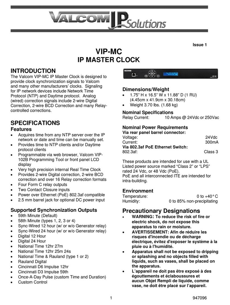
Valcom V-WMCA Series User manual

Valcom

Valcom V-WMCA Series User manual

Valcom V-AW12A User manual

Valcom

Valcom V-AW12A User manual

Valcom VIP-A12 User manual

Valcom

Valcom VIP-A12 User manual

Valcom VIP-429A-A-SA User manual

Valcom

Valcom VIP-429A-A-SA User manual

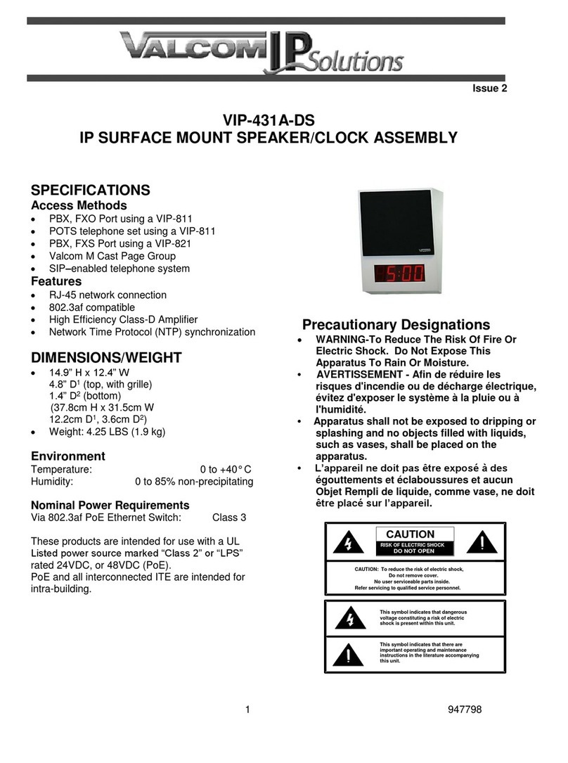
Valcom VIP-431A-DS User manual

Valcom

Valcom VIP-431A-DS User manual

Valcom InformaCast VIP-431-A-IC User manual

Valcom

Valcom InformaCast VIP-431-A-IC User manual

Valcom VIP-A12ADS User manual

Valcom

Valcom VIP-A12ADS User manual

Valcom V-A2412 User manual

Valcom

Valcom V-A2412 User manual

Valcom V-DW11025B Assembly instructions

Valcom

Valcom V-DW11025B Assembly instructions

Valcom VIP-D625 User manual

Valcom

Valcom VIP-D625 User manual

Valcom V-WMCA User manual

Valcom

Valcom V-WMCA User manual

Valcom VE4122-A12 User manual

Valcom

Valcom VE4122-A12 User manual

Valcom V-A2412 User manual

Valcom

Valcom V-A2412 User manual

Valcom 12" User manual

Valcom

Valcom 12" User manual

Valcom VIP-D425ADS User manual

Valcom

Valcom VIP-D425ADS User manual

Valcom VIP-D425 User manual

Valcom

Valcom VIP-D425 User manual

Valcom V-AW12A User manual

Valcom

Valcom V-AW12A User manual

Valcom VIP-A12A User manual

Valcom

Valcom VIP-A12A User manual

Valcom V-D11025B User manual

Valcom

Valcom V-D11025B User manual

Valcom VIP-429A-A-IC User manual

Valcom

Valcom VIP-429A-A-IC User manual

Valcom V-D2425 User manual

Valcom

Valcom V-D2425 User manual

Valcom VIP-D425DS User manual

Valcom

Valcom VIP-D425DS User manual

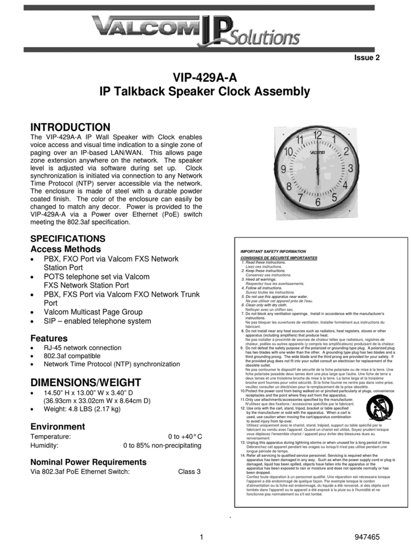
Valcom VIP-429A-A User manual

Valcom

Valcom VIP-429A-A User manual

Valcom V-D2425B Assembly instructions

Valcom

Valcom V-D2425B Assembly instructions

Popular Clock manuals by other brands

Sapling NTP 7000 Series installation manual

Sapling

Sapling NTP 7000 Series installation manual

Amano MTX-30F Installation & operation guide

Amano

Amano MTX-30F Installation & operation guide

La Crosse Technology BBB86118v3 Setup guide

La Crosse Technology

La Crosse Technology BBB86118v3 Setup guide

BEARWARE 304474 manual

BEARWARE

BEARWARE 304474 manual

LS & S RTC103U instruction manual

LS & S

LS & S RTC103U instruction manual

BitGen Technologies LED Walk/Don't Walk Clock user manual

BitGen Technologies

BitGen Technologies LED Walk/Don't Walk Clock user manual

Heathkit GC-1005 Assembly manual

Heathkit

Heathkit GC-1005 Assembly manual

Oregon Scientific PRYSMA RMR221P manual

Oregon Scientific

Oregon Scientific PRYSMA RMR221P manual

Andrew O'Malley DOTKLOK Assembly instructions

Andrew O'Malley

Andrew O'Malley DOTKLOK Assembly instructions

Nixie Clock Divergence Meter user manual

Nixie Clock

Nixie Clock Divergence Meter user manual

La Crosse Technology WS-8256-AL user manual

La Crosse Technology

La Crosse Technology WS-8256-AL user manual

Mini Gadgets MCPro user manual

Mini Gadgets

Mini Gadgets MCPro user manual

Casio TMR-200 user guide

Casio

Casio TMR-200 user guide

Progetti KALIMERO Directions

Progetti

Progetti KALIMERO Directions

Progetti ILTEMPOSTRINGE Directions

Progetti

Progetti ILTEMPOSTRINGE Directions

La Crosse Technology WT-3141b Quick setup instructions

La Crosse Technology

La Crosse Technology WT-3141b Quick setup instructions

IKEA ROTBLÖTA manual

IKEA

IKEA ROTBLÖTA manual

U-Line Н-2811 instructions

U-Line

U-Line Н-2811 instructions

manuals.online logo
manuals.online logoBrands
  • About & Mission
  • Contact us
  • Privacy Policy
  • Terms and Conditions

Copyright 2025 Manuals.Online. All Rights Reserved.

Issue 1
1947557
CAUTION: To reduce the risk of electric shock,
Do not remove cover (or back).
No user serviceable parts inside.
Refer servicing to qualified service personnel.
CAUTION
RISK OF ELECTRIC SHOCK
DO NOT OPEN
This symbol indicates that dangerous
voltage constituting a risk of electric
shock is present within this unit.
This symbol indicates that there are
important operating and maintenance
instructions in the literature accompanying
this unit.
Issue 2
VE4171-D440
IP DIGITAL 4 DIGIT CLOCK/WALL MOUNT SPEAKER
INTRODUCTION
The VE4171-D440 IP Clock with Speaker includes
a 4” Digital Clock and a Wall Mount Speaker. The
wall speaker is an 8” interior talkback speaker. This
provides synchronized time, talkback intercom and
loudspeaker paging from one IP network
connection. The 4-digit Digital Clock can be
programmed to sync with any NTP (Network Time
Protocol) server. The clock and speaker
enclosures are made of steel with a durable powder
coated finish. The color of the enclosures can be
easily changed to match any décor. A cloth
covered detachable grille is included with the
speaker. Power is provided to both the clock and
speaker via a Power over Ethernet (PoE) switch
meeting the 802.3af specification.
SPECIFICATIONS
Features
RJ-45 network connection
Easy to read, high visibility Red digits display
hours and minutes (4 digit display)
Selectable 12 or 24 hour format
Power over Ethernet (PoE) 802.3af compatible
High Efficiency
DIMENSIONS/WEIGHT –4 Digit
VIP-D440A - 17.00” L x 3.00” W x 6.75” H
(43.18 cm) X (7.62 cm) X (17.14 cm)
Weight: 4.50 LBS (2.0 kg)
V-1071 - 10.13” H x 12.31” W x 4.63” D
(25.73cm x 31.27cm W x 11.75cm D)
Weight: 4.25 LBS (1.9 kg)
Nominal Power Requirements
Via 802.3af PoE Ethernet Switch: Class 3
Environment
Temperature: 0 to +40° C
Humidity: 0 to 85% non-precipitating
Precautionary Designations
INSTALLATION
FCC Information
This equipment has been tested and found to
comply with the limits for a Class A digital
device, pursuant to Part 15 of the FCC Rules.
These limits are designed to provide reasonable
protection against harmful interference when
the equipment is operated in a commercial
environment. This equipment generates, uses
and can radiate radio frequency energy and if
not installed and used in accordance with the
instruction manual, may cause harmful
interference to radio communications.
Operation of this equipment in a residential area
may cause harmful interference in which case
the user will be required to correct the
interference at one’s own expense.
2947557
SPEAKER
LED 1
LED 2
-10dB LINE
LEVEL OUT
MUTE
SWITCH 2
SWITCH 1
GROUND
NETWORK
RESET
+
-
-+
RED
BLACK
Clock Mounting
Remove the side screws holding the mounting
plate/rear panel to the enclosure. Mount the plate
to the wall or a standard double-gang electrical box
using appropriate hardware such as #8 pan head
screws (not supplied). After making the required
connections, reattach the enclosure to the
mounting plate, rear panel.
Speaker Mounting
Remove the screw holding the mounting bracket to
the enclosure. Mount the bracket using appropriate
hardware such as #8 pan head crews. After
making the required connections, reattach the
enclosure to the mounting bracket.
Speaker Connections
Connect the attached wire assembly from the
V-1071 to the Speaker screw connections on
the clock circuit board.
Network Connection
The VE4171-D440 has one RJ-45 network
connector on the rear panel. Connect a standard
Ethernet patch cable from the VE4171-D440 into an
Ethernet switch. If a PoE switch is not available, a
PoE mid-span injector may be used to supply
power to the clocks.
IP CLOCK/SPEAKER CONNECTIONS
Call Switch Connection
For IP Speakers using Talkback functionality, a call
switch input via screw terminals is provided.
Connect a momentary contact switch to Switch 1
and Ground.
-10 dB Line Level Out Connection
The -10dBm Line Level Out may be connected to
up to 40 Valcom Self Amplified Speakers in order to
provide additional sound reinforcement in an area.
Mute Out Connection
The Mute Out may optionally be connected to the
mute input of Valcom audio management systems
in order to suspend locally originated audio during
intercom announcements.
LED 1 and LED 2 Connection
LED 1 (+) and LED 2 (-) is a current limited output
designed to illuminate an optional LED. The LED
is intended to provide visual indication of call
progress. The LED illumination will flash when the
call switch is pressed and will continue to flash until
the call is answered. The LED illumination will be
solid when a connection to the unit is established.
SETUP
Information specific to your application will need to
be programmed into the VIP’s using a computer.
The PC used for programming should be connected
to the same subnet as the VIP’s. Setup will be
done using the IP Solutions Setup Tool. Download
the latest version of the free IP Solutions Setup
Tool from Valcom web site at
www.valcom.com/vipsetuptool.
3947557
TECHNICAL ASSISTANCE
When trouble is reported, verify power is being
supplied to the unit and there are no broken
connections. If a spare unit is available, substitute a
spare unit for the suspected defective unit.
Assistance in troubleshooting is available from the
factory. Call (540) 563-2000 and press 1 for
Technical Support or visit our website at
http://www.valcom.com or via email at
support@valcom.com
Valcom equipment is not field-repairable. Valcom,
Inc. maintains service facilities in Roanoke, VA.
Should repairs be necessary, attach a tag to the
unit clearly stating your company name, address,
phone number, contact person and the nature of
the problem. Send the unit to:
Valcom, Inc.
Repair & Return Dept.
5614 Hollins Road
Roanoke, Va. 24019-5056
WARRANTY
Warranty information may be found on our website
at www.valcom.com/warranty.