manuals.online logo
Brands
  1. Home
  2. •
  3. Brands
  4. •
  5. Valcom
  6. •
  7. Clock
  8. •
  9. Valcom VIP-429A-A-SA User manual

Valcom VIP-429A-A-SA User manual

Other Valcom Clock manuals

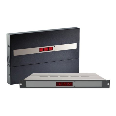
Valcom VE4171-D440 User manual

Valcom

Valcom VE4171-D440 User manual

Valcom V-D2425B Assembly instructions

Valcom

Valcom V-D2425B Assembly instructions

Valcom VIP-A12 User manual

Valcom

Valcom VIP-A12 User manual

Valcom VIP-A12ADS User manual

Valcom

Valcom VIP-A12ADS User manual

Valcom V-D2425 User manual

Valcom

Valcom V-D2425 User manual

Valcom V-D11025A Assembly instructions

Valcom

Valcom V-D11025A Assembly instructions

Valcom VIP-D625 User manual

Valcom

Valcom VIP-D625 User manual

Valcom VE4122-A12 User manual

Valcom

Valcom VE4122-A12 User manual

Valcom V-WMCA User manual

Valcom

Valcom V-WMCA User manual

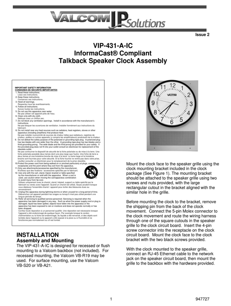
Valcom InformaCast VIP-431-A-IC User manual

Valcom

Valcom InformaCast VIP-431-A-IC User manual

Valcom VIP-MC User manual

Valcom

Valcom VIP-MC User manual

Valcom VIP-D425A User manual

Valcom

Valcom VIP-D425A User manual

Valcom VIP-D425DS User manual

Valcom

Valcom VIP-D425DS User manual

Valcom VIP-A12ADS User manual

Valcom

Valcom VIP-A12ADS User manual

Valcom VIP-D425ADS User manual

Valcom

Valcom VIP-D425ADS User manual

Valcom VIP-A12A User manual

Valcom

Valcom VIP-A12A User manual

Valcom V-A2412 User manual

Valcom

Valcom V-A2412 User manual

Valcom IP Solutions VIP-A12DS User manual

Valcom

Valcom IP Solutions VIP-A12DS User manual

Valcom V-A2412 User manual

Valcom

Valcom V-A2412 User manual

Valcom V-AW12A User manual

Valcom

Valcom V-AW12A User manual

Valcom V-D11025B User manual

Valcom

Valcom V-D11025B User manual

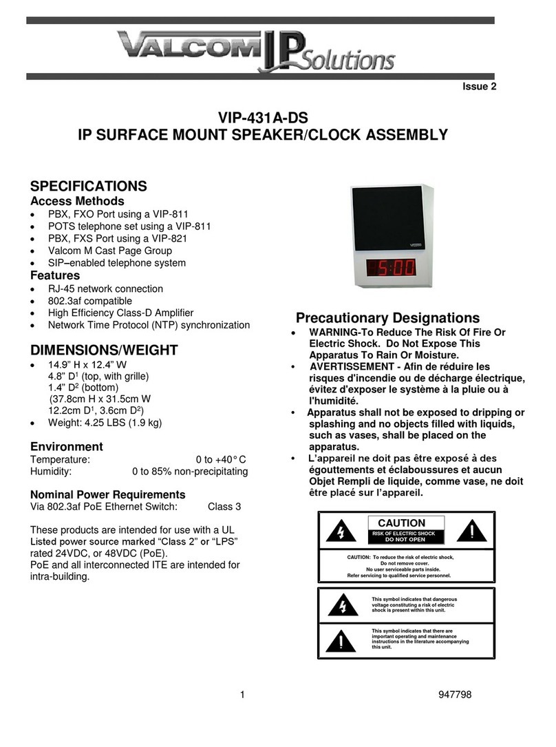
Valcom VIP-431A-DS User manual

Valcom

Valcom VIP-431A-DS User manual

Valcom V-WMCA Series User manual

Valcom

Valcom V-WMCA Series User manual

Valcom VIP-D425 User manual

Valcom

Valcom VIP-D425 User manual

Popular Clock manuals by other brands

Sapling NTP 7000 Series installation manual

Sapling

Sapling NTP 7000 Series installation manual

Amano MTX-30F Installation & operation guide

Amano

Amano MTX-30F Installation & operation guide

La Crosse Technology BBB86118v3 Setup guide

La Crosse Technology

La Crosse Technology BBB86118v3 Setup guide

BEARWARE 304474 manual

BEARWARE

BEARWARE 304474 manual

LS & S RTC103U instruction manual

LS & S

LS & S RTC103U instruction manual

BitGen Technologies LED Walk/Don't Walk Clock user manual

BitGen Technologies

BitGen Technologies LED Walk/Don't Walk Clock user manual

Heathkit GC-1005 Assembly manual

Heathkit

Heathkit GC-1005 Assembly manual

Oregon Scientific PRYSMA RMR221P manual

Oregon Scientific

Oregon Scientific PRYSMA RMR221P manual

Andrew O'Malley DOTKLOK Assembly instructions

Andrew O'Malley

Andrew O'Malley DOTKLOK Assembly instructions

Nixie Clock Divergence Meter user manual

Nixie Clock

Nixie Clock Divergence Meter user manual

La Crosse Technology WS-8256-AL user manual

La Crosse Technology

La Crosse Technology WS-8256-AL user manual

Mini Gadgets MCPro user manual

Mini Gadgets

Mini Gadgets MCPro user manual

Casio TMR-200 user guide

Casio

Casio TMR-200 user guide

Progetti KALIMERO Directions

Progetti

Progetti KALIMERO Directions

Progetti ILTEMPOSTRINGE Directions

Progetti

Progetti ILTEMPOSTRINGE Directions

La Crosse Technology WT-3141b Quick setup instructions

La Crosse Technology

La Crosse Technology WT-3141b Quick setup instructions

IKEA ROTBLÖTA manual

IKEA

IKEA ROTBLÖTA manual

U-Line Н-2811 instructions

U-Line

U-Line Н-2811 instructions

manuals.online logo
manuals.online logoBrands
  • About & Mission
  • Contact us
  • Privacy Policy
  • Terms and Conditions

Copyright 2025 Manuals.Online. All Rights Reserved.

Issue 1
1947566
VIP-429A-A-SA
Syn-Apps® Compliant
IP Talkback Speaker Clock Assembly
SPECIFICATIONS
Access Methods
Syn-Apps Server
PBX, FXO Port via Valcom FXS Network
Station Port
POTS telephone set via Valcom
FXS Network Station Port
PBX, FXS Port via Valcom FXO Network Trunk
Port
Valcom Multicast Page Group
SIP –enabled telephone system
Features
RJ-45 network connection
802.3af compatible
Network Time Protocol (NTP) synchronization
DIMENSIONS/WEIGHT
14.50” H x 13.00” W x 3.40” D
(36.93cm x 33.02cm W x 8.64cm D)
Weight: 4.8 LBS (2.17 kg)
Environment
Temperature: 0 to +40° C
Humidity: 0 to 85% non-precipitating
Nominal Power Requirements
Via 802.3af PoE Ethernet Switch: Class 3
These products are intended for use with a UL
Listed power source marked “Class 2” or “LPS”
rated 24VDC, or 48VDC (PoE).
PoE and all interconnected ITE are intended for
intra-building.
IMPORTANT SAFETY INFORMATION
CONSIGNES DE SÉCURITÉ IMPORTANTES
1. Read these instructions.
Lisez ces instructions.
2. Keep these instructions.
Conservez ces instructions.
3. Heed all warnings.
Respecteztous les avertissements.
4. Follow all instructions.
Suivez toutes les instructions.
5. Do not use this apparatus near water.
Ne pas utiliser cet appareil près de l'eau.
6. Clean only with dry cloth.
Nettoyer avec un chiffon sec.
7. Do not block any ventilation openings. Install in accordance with the manufacturer’s
instructions.
Ne pas bloquer les ouvertures de ventilation. Installer formément aux instructions du
fabricant.
8. Do not install near any heat sources such as radiators, heat registers, stoves or other
apparatus (including amplifiers) that produce heat.
Ne pas installer à proximité de sources de chaleur telles que radiateurs, registres de
chaleur, poêles ou autres appareils (y compris les amplificateurs) produisant de la chaleur.
9. Do not defeat the safety purpose of the polarized or grounding-type plug. A polarized plug
has two blades with one wider than the other. A grounding type plug has two blades and a
third grounding prong. The wide blade and the third prong are provided for your safety. If
the provided plug does not fit into your outlet consult an electrician for replacement of the
obsolete outlet.
Ne pas contourner le dispositif de sécurité de la fiche polarisée ou demise à la terre. Une
fiche polarisée possède deux lames dont une plus large que l'autre. Une fiche de terre a
deux lames et une troisième broche de mise à la terre. La lame large et la troisième
broche sont fournies pour votre sécurité. Si la fiche fournie ne rentre pas dans votre prise,
veuillez consulter un électricien pour le remplacement de la prise obsolète.
10.Protect the power cord from being walked on or pinched particularly at plugs, convenience
receptacles and the point where they exit from the apparatus.
11.Only use attachments/accessories specified by the manufacturer.
N'utilisez que des fixations / accessoires spécifiés par le fabricant.
12. Use only with the cart, stand, tripod, bracket or table specified
by the manufacturer or sold with the apparatus. When a cart is
used, use caution when moving the cart/apparatus combination
to avoid injury from tip-over.
Utilisez uniquement avec le chariot, stand, trépied, support ou table spécifié par le
fabricant ou vendu avec l'appareil. Quand un chariot est utilisé, Soyez prudent lorsque
vous déplacez l'ensemble chariot / appareil pour éviter des blessures dues au
renversement.
13. Unplug this apparatus during lightning storms or when unused for a long period of time.
Débranchez cet appareil pendant les orages ou lorsqu'il n'est pas utilisé pendant une
longue période de temps.
14. Refer all servicing to qualified service personnel. Servicing is required when the
apparatus has been damaged in any way. Such as when the power supply cord or plug is
damaged, liquid has been spilled, objects have fallen into the apparatus or the
apparatus has been exposed to rain or moisture and does not operate normally or has
been dropped.
Confiez toute réparation à un personnel qualifié. Une réparation est nécessaire lorsque
l'appareil a été endommagé de quelque façon. Par exemple lorsque le cordon
d'alimentation oula fiche est endommagé, du liquide a été renversé, si des objets sont
tombés dans l'appareil ou le appareil a été exposé à la pluie ou àl'humidité et ne
fonctionne pas normalement ou s'il est tombé.
2947566
.

VB-R22
VB-S23
VB-A24
Figure 1. Assembly and Mounting
3947566
INSTALLATION
Assembly and Mounting
The VIP-429A-A-SA is designed for recessed or
flush mounting to a Valcom backbox (not included).
For recessed mounting, the Valcom VB-R22 may
be used. For surface mounting, use the Valcom
VB-S23 or VB-A24.
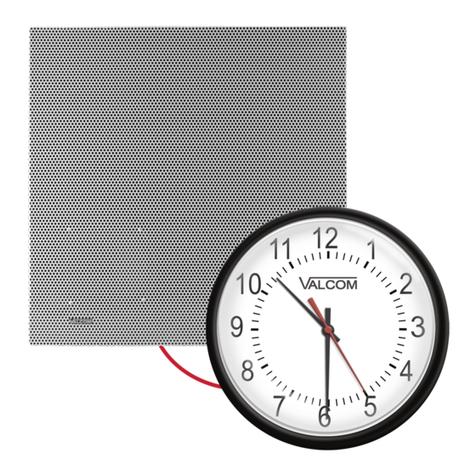
Mount the clock face to the speaker grille using the
clock mounting bracket included in the clock
package (See Figure 1). The mounting bracket
should be attached to the speaker grille using two
screws and nuts provided, with the large
rectangular cutout in the bracket aligned with the
similar hole in the grille.
Before mounting the clock to the bracket, remove
the shipping pin from the back of the clock
movement. Connect the 5-pin Molex connector to
the clock movement and route the wiring harness
through one of the square cutouts in the speaker
grille to the clock circuit board. Insert the 4-pin
screw connector into the receptacle on the clock
circuit board. Mount the clock face to the clock
bracket with the two black screws provided.
With the clock mounted to the speaker grille,
connect an RJ-45 Ethernet cable to the network
jack on the speaker circuit board, then mount the
grille to the backbox with the hardware provided.
Network Connection
The VIP-429A-A-SA has one RJ-45 network
connector on the rear panel. Use a standard patch
cable to connect the VIP-429A-A-SA to an Ethernet
switch providing Power over Ethernet (PoE)
meeting the 802.3af specification. If the switch
does not provide power, a mid-span power injector
may be used. (See Figure 2)
Mute Out Connection
The Mute Out may optionally be connected to the
mute input of Valcom Classroom audio
management systems in order to suspend locally
originated classroom audio during intercom
announcements.
Call Switch Connection
The Talkback IP Speaker provides a call switch
input via screw terminal connections. Connect a
momentary contact switch to Switch 1 and Ground.
Figure 2. Connections
4947566
-10dB Line Level Out Connection
The -10dB Line Level Out may be connected to up
to 40 Valcom Self Amplified Speakers in order to
provide additional sound reinforcement in an area.
LED Connection
LED 1 (+) and LED 2 (-) is a current limited output
designed to illuminate an optional LED. The LED is
intended to provide visual indication of call
progress. The LED illumination will flash when the
call switch is pressed and will continue to flash until
the call is answered. The LED illumination will be
solid when a connection to the unit is established.
Setup
The VIP-429A-A-SA will automatically acquire an
IP address (using DHCP) and connect to the
Syn-Apps server when connected to the network
and powered up. Time synchronization is provided
by any NTP server. NTP server can be defined in
the DHCP scope or manually. Information specific
to your application will need to be programmed into
the Syn-Apps server. Refer to the Syn-Apps
documentation for further information.
TECHNICAL ASSISTANCE
When trouble is reported, verify power is being
supplied to the unit and there are no broken
connections. If a spare unit is available, substitute
a spare unit for the suspected defective unit.
Assistance in troubleshooting is available from the
factory. Call (540) 563-2000 and press 1 for
Technical Support. When requesting assistance,
you should include all available information.
It is strongly suggested that you also review
available documentation on
http://www.valcom.com/syn-apps.
Valcom equipment is not field repairable. Valcom,
Inc. maintains service facilities in Roanoke, VA.
Should repairs be necessary, attach a tag to the
unit clearly stating your company name, address,
phone number, contact person and the nature of
the problem. Send the unit to:
Valcom, Inc.
Repair & Return Dept.
5614 Hollins Road
Roanoke, Va. 24019-5056
WARRANTY
Warranty information may be found on our website
at www.valcom.com/warranty