manuals.online logo
Brands
  1. Home
  2. •
  3. Brands
  4. •
  5. Valcom
  6. •
  7. Horn
  8. •
  9. Valcom VIP-130L-IC User manual

Valcom VIP-130L-IC User manual

Other Valcom Horn manuals
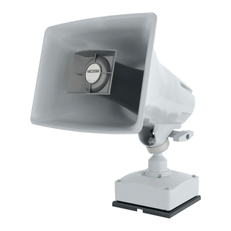
Valcom V-1048B User manual

Valcom

Valcom V-1048B User manual

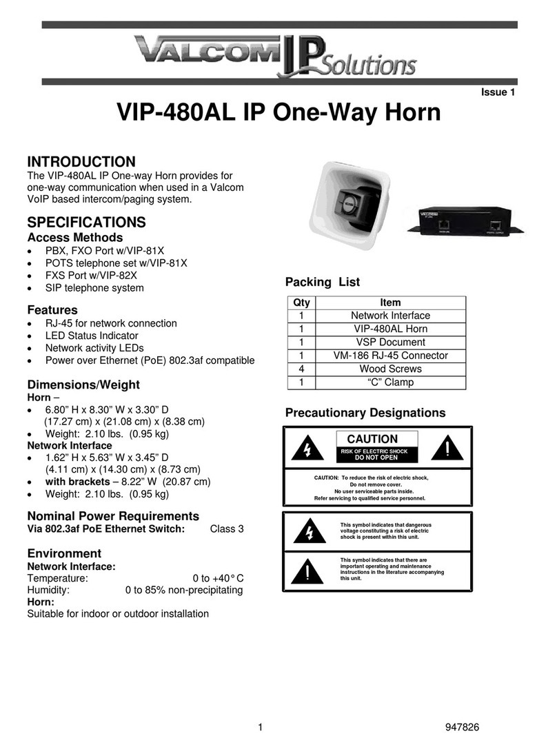
Valcom VIP-480AL User manual

Valcom

Valcom VIP-480AL User manual

Valcom InformaCast VIP-142-IC User manual

Valcom

Valcom InformaCast VIP-142-IC User manual

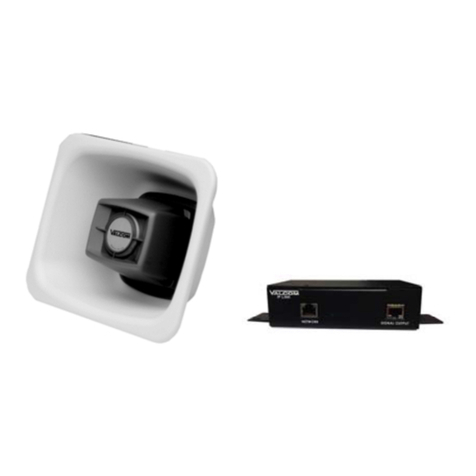
Valcom VIP-480AL-SA User manual

Valcom

Valcom VIP-480AL-SA User manual

Valcom V-1039A User manual

Valcom

Valcom V-1039A User manual

Valcom V-1080 Flexhorn User manual

Valcom

Valcom V-1080 Flexhorn User manual

Valcom V-1030C Manual

Valcom

Valcom V-1030C Manual

Valcom V-1030M User manual

Valcom

Valcom V-1030M User manual

Valcom VIP-148AL User manual

Valcom

Valcom VIP-148AL User manual

Valcom V-1090- BG User manual

Valcom

Valcom V-1090- BG User manual

Valcom VIP-480L User manual

Valcom

Valcom VIP-480L User manual

Valcom FLEXHORN V-1090 User manual

Valcom

Valcom FLEXHORN V-1090 User manual

Valcom Revolution VIP-142-SA User manual
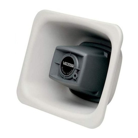
Valcom

Valcom Revolution VIP-142-SA User manual

Valcom VIP-130AL-IC User manual

Valcom

Valcom VIP-130AL-IC User manual

Valcom VIP-480L User manual

Valcom

Valcom VIP-480L User manual

Valcom V-1030C User manual

Valcom

Valcom V-1030C User manual

Valcom IP Solutions VIP-9880 User manual
Valcom

Valcom IP Solutions VIP-9880 User manual

Valcom PagePac V-5331200 User manual

Valcom

Valcom PagePac V-5331200 User manual

Valcom IP Solutions VIP-483 User manual

Valcom

Valcom IP Solutions VIP-483 User manual

Valcom VIP-130AL-SA User manual

Valcom

Valcom VIP-130AL-SA User manual

Valcom VIP-480L User manual

Valcom

Valcom VIP-480L User manual

Valcom V-1048C User manual

Valcom

Valcom V-1048C User manual

Valcom V-1038 User manual

Valcom

Valcom V-1038 User manual

Valcom VIP-142 User manual

Valcom

Valcom VIP-142 User manual

Popular Horn manuals by other brands

Klenn Air Horns JL-JK-OBA installation manual

Klenn Air Horns

Klenn Air Horns JL-JK-OBA installation manual

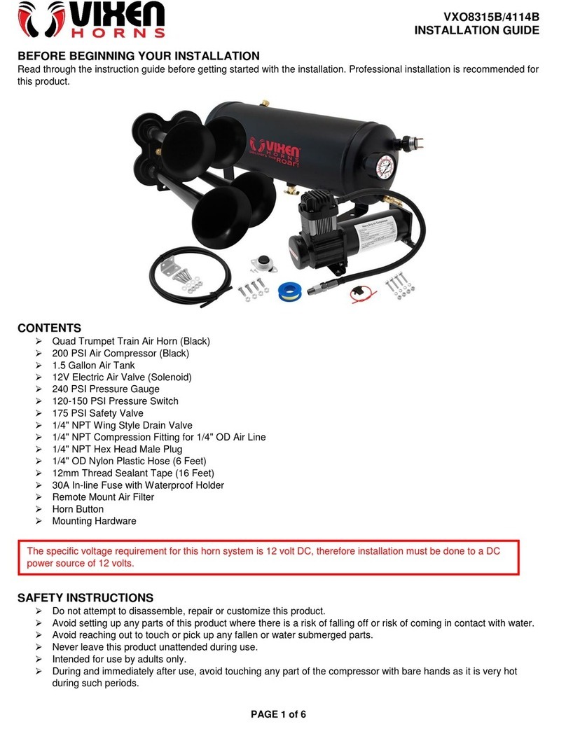
Vixen Horns VXO8350 installation guide

Vixen Horns

Vixen Horns VXO8350 installation guide

Elk Products 45 user manual

Elk Products

Elk Products 45 user manual
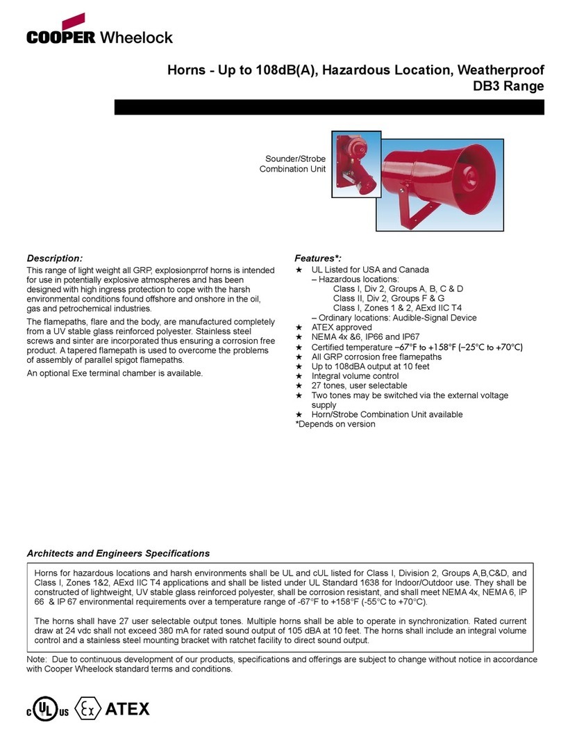
Cooper Wheelock DB3 Series specification
Cooper Wheelock

Cooper Wheelock DB3 Series specification

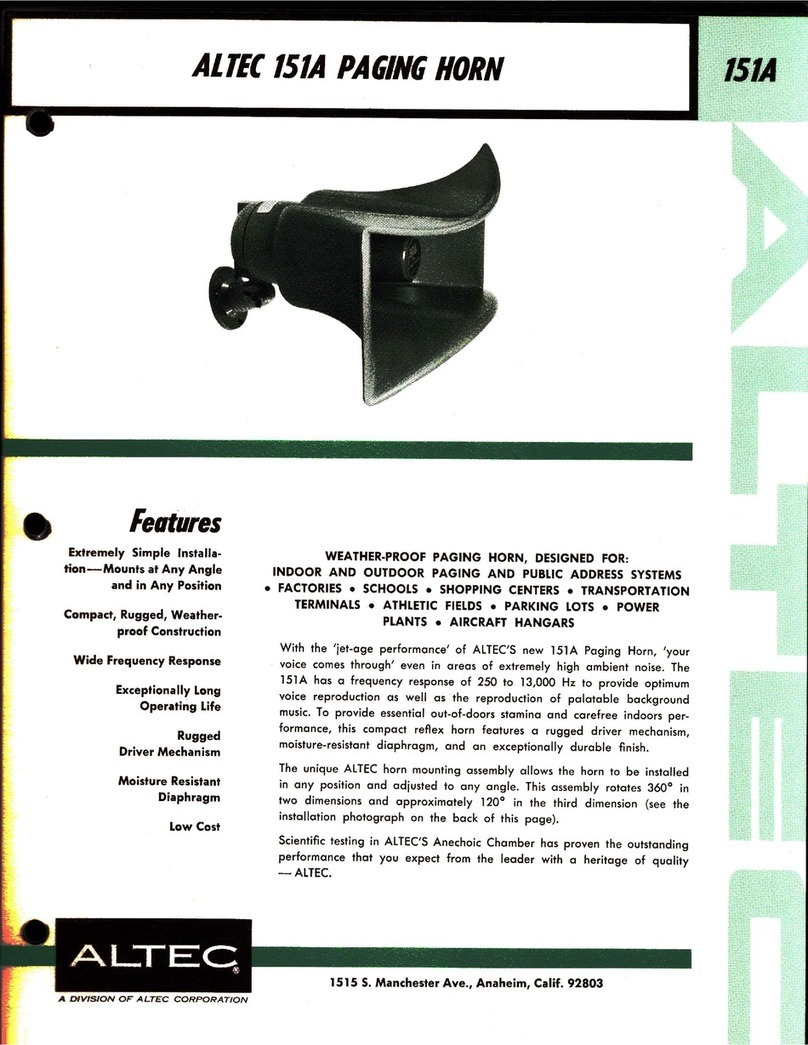
Altec Lansing 811B HF HORN manual

Altec Lansing

Altec Lansing 811B HF HORN manual

RF Elements UltraHorn CC Series quick start guide

RF Elements

RF Elements UltraHorn CC Series quick start guide

Edwards Signaling 869DSTR-G1 Series Installation sheet
Edwards Signaling

Edwards Signaling 869DSTR-G1 Series Installation sheet

Toa LE-M124 Specifications

Toa

Toa LE-M124 Specifications

AUSTRALIAN MONITOR MH30 brochure

AUSTRALIAN MONITOR

AUSTRALIAN MONITOR MH30 brochure

Vixen Horns VXO8805/3311C installation guide

Vixen Horns

Vixen Horns VXO8805/3311C installation guide

Federal Signal Corporation 350 Installation and maintenance instructions

Federal Signal Corporation

Federal Signal Corporation 350 Installation and maintenance instructions

Electro-Voice MH4020AC Specifications

Electro-Voice

Electro-Voice MH4020AC Specifications

Dynacord 18" Full-W Vented Bass Horn alpha B6 Specifications

Dynacord

Dynacord 18" Full-W Vented Bass Horn alpha B6 Specifications

Kleinn RAMHDOBA-6450 installation instructions

Kleinn

Kleinn RAMHDOBA-6450 installation instructions

Vixen Horns VXO8715/4124B installation guide

Vixen Horns

Vixen Horns VXO8715/4124B installation guide

Wheelock HS-24 installation instructions

Wheelock

Wheelock HS-24 installation instructions

Altec Lansing MR945A HF HORN manual

Altec Lansing

Altec Lansing MR945A HF HORN manual

Vixen Horns VXO8530/3311B installation guide

Vixen Horns

Vixen Horns VXO8530/3311B installation guide

manuals.online logo
manuals.online logoBrands
  • About & Mission
  • Contact us
  • Privacy Policy
  • Terms and Conditions

Copyright 2025 Manuals.Online. All Rights Reserved.

1 947728
ISSUE 4
VIP-130L-IC InformaCast® Compliant
IP Paging Horn
Installation
Mounting (VIP-LLE)
The VIP-LLE Network Extender is designed for
wall or shelf mounting and must be within 300
feet of the network switch.
Shelf: Provided with the VIP-LLE Network
Extender are four rubber pads. Peel the pads
from the carrier backing and place at the four
corners of the bottom of the unit.
Wall: Using the brackets and wood screws
provided, secure the VIP-LLE Network Extender
to the wall.
Mounting (Horn)
The horn should be mounted 15 to 20 feet
above the floor to allow for best sound
distribution. The unit can be mounted to a wall,
a beam or an electrical box.
NOTE: For ease of installation, the base can be
attached to the speaker before or after the base
is mounted.
Loosen position adjustment knob
Insert the ball of the base into the socket
of the speaker
Tighten the position adjustment knob
Mount the base to a wall using the two
holes provided. Knockout holes are
provided for punch out should additional
holes be desired.
A “C” clamp is provided with the horn to
allow mounting to a beam. Place the
bolt through the hole in the bottom of the
base to secure the “C” clamp to the
beam. It is suggested that the horn be
mounted to the underside of the “I”
beam to provide maximum positioning
adjustments.
The base has pre-drilled holes for a
double-gang square electrical box, but
by drilling out additional knockout holes,
the base can be mounted to a single-
gang or octagon box
The horn may be rotated or moved up and down
to obtain the desired position by loosening the
position adjustment knob at the bottom of the
unit approximately one turn. Make required
adjustments and re-tighten knob.
2 947728
Interconnections
The only method of powering the VIP-130L-IC IP
Paging Horn is via a Power over Ethernet (PoE)
switch or power injector meeting the 802.3af
specification.
Make all required signal connections before
connecting to Ethernet switch or power injector
meeting the 802.3af specification. Power is
supplied to the horn assembly via the
VIP-LLE Network Extender.
Signal Connections
As shown in Figure 3 and 4, audio output
connections are made on the rear panel of the
VIP-LLE Network Extender. Versions of the
VIP-LLE Network Extender with the color-coded,
8-pin screw connector will connect standard
CAT-5 twisted-pair cable from the rear panel
color coded connector of the VIP-LLE Network
Extender to the supplied VM-186 RJ-45
connector (900 feet maximum distance).
Connect RJ-45 connector of horn to VM-186
RJ-45 socket. For versions of the VIP-LLE
Network Extender with the RJ-45 Audio Output
connector, the horn may be connected directly
to the RJ-45 port. If additional length is
required, any standard T568A or T568B
extension may be used (900 feet maximum).
Network Connection
As shown in Figure 3, the VIP-LLE Network
Extender has one RJ-45 network connector on
the front panel. Use a standard Ethernet patch
cable to connect the NETWORK connector of
the VIP-LLE Network Extender to an 802.3af
compliant PoE port (100m maximum distance).
Setup
The VIP-130L-IC will automatically acquire an IP
address (using DHCP) and connect to the
InformaCast server when connected to the
network and powered up. Information specific to
your application will need to be programmed into
the InformaCast server. Refer to the
InformaCast documentation for further
information.
Status Indicator Lights
The VIP-LLE Network Extender has 3 status
indication lights:
STATUS: Flashes during normal operation, and
solid when unit in reset.
LINK: Indicates 100 Mbit Ethernet connection
when illuminated. No activity indicates 10 Mbit
connection.
Act: Indicator flashes to indicate network
activity
3 947728
ALCOM
V
VIP-LLE
W/BL W/O W/GN W/BR
900' MAX DISTANCE
CAT 3/5/6
802.3af Compliant PoE Network Port
Paging Horn
Status
Link
Act
WHITE/BLUE
BLUE
WHITE/GREEN
GREEN
WHITE/BROWN
BROWN
WHITE/ORANGE
NOT USED
Front View
Rear View with Screw Terminal Connector
VM-186
RJ45
BROWN
BLUE
WHITE/BLUE
BLUE
WHITE/ORANGE
ORANGE
WHITE/GREEN
GREEN
WHITE/BROWN
BROWN
Note: The Brown and White/brown pair should
be twisted together and inserted into the
connector noted on the drawing and the Green
and White/Green pair should also be twisted
together and inserted into the connector that is
noted on the drawing.
Note: The screw terminals are removable.
Gently lift away from the circuit board to
remove. Make the necessary wire connections,
then replace the screw terminals over the pins
on circuit board.
There are two versions of the VIP-LLE.
Refer to the diagram below that corresponds to the version being installed.
Figure 3. (VIP-LLE versions with 8-pin screw terminal output connector.)
IP Paging Horn
AUDIO OUTPUT
Rear View with RJ-45 Connector
Figure 4. (VIP-LLE versions with RJ-45 output connector.)
If using the VM-186 or other patch panel to extend the connection between the VIP-LLE (with RJ-45 connector)
and the Paging Horn, use standard T568B wiring connections.
4 947728
TECHNICAL ASSISTANCE
Assistance in troubleshooting is available from
the factory. Call (540) 563-2000 and press 1 for
Technical Support or via email at
[email protected].
When requesting assistance, you should include
all available information. It is strongly suggested
that you go to the website and review the
information at www.valcom.com/informacast.
Valcom equipment is not field repairable.
Valcom, Inc. maintains service facilities in
Roanoke, VA. Should repairs be necessary,
attach a tag to the unit clearly stating your
company name, address, phone number,
contact person and the nature of the problem.
Send the unit to: Valcom, Inc.
Repair & Return Dept.
5614 Hollins Road
Roanoke VA. 24019
VALCOM LIMITED WARRANTY
Valcom, Inc. warrants its products only to the original purchaser, for its own use, to be free from defects in materials and workmanship under
conditions of normal use and service for a period of one year from the date of shipment. This Limited Warranty obligation shall be limited to the
replacement, repair or refund of any such defective device within the warranty period, provided that:
1. inspection by Valcom, Inc. indicates the validity of the claim;
2. the defect is not the result of damage, misuse or negligence after the original shipment;
3. the product has not been altered in any way or repaired by others and that factory sealed units are unopened (a service charge plus parts
and labor will be applied to units defaced or physically damaged);
4. freight charges for the return of products to Valcom are prepaid;
5. all units 'out of warranty' are subject to a service charge. The service charge will cover minor repairs (major repairs will be subject to
additional charges for parts and labor).
This Limited Warranty is in lieu of and excludes all other warranties, expressed or implied and in no event shall Valcom, Inc. be liable
for any anticipated profits, consequential damages, loss of time or other losses incurred by the buyer in connection with the purchase,
operation, maintenance, installation, removal or use of the product. The maximum liability of Valcom under this warranty is limited to
the purchase price of the specific Product covered by the warranty.
Disclaimer. Except for the Limited Warranty provided herein, the product is provided “as-is” without any warranty of any kind whatsoever
including, without limitation, any WARRANTY OF MERCHANTABILITY, FITNESS FOR A PARTICULAR PURPOSE OR NON-INFRINGEMENT.
This warranty specifically excludes damage incurred in shipment. In the event a product is received in damaged condition, the carrier should be
notified immediately. Claims for such damage should be filed with the carrier involved in accordance with the F.O.B. point.
Headquarters:
Valcom, Inc.
5614 Hollins Road Roanoke, VA 24019-5056
Phone: (540) 563-2000 FAX: (540) 362-9800