manuals.online logo
Brands
  1. Home
  2. •
  3. Brands
  4. •
  5. Valcom
  6. •
  7. Horn
  8. •
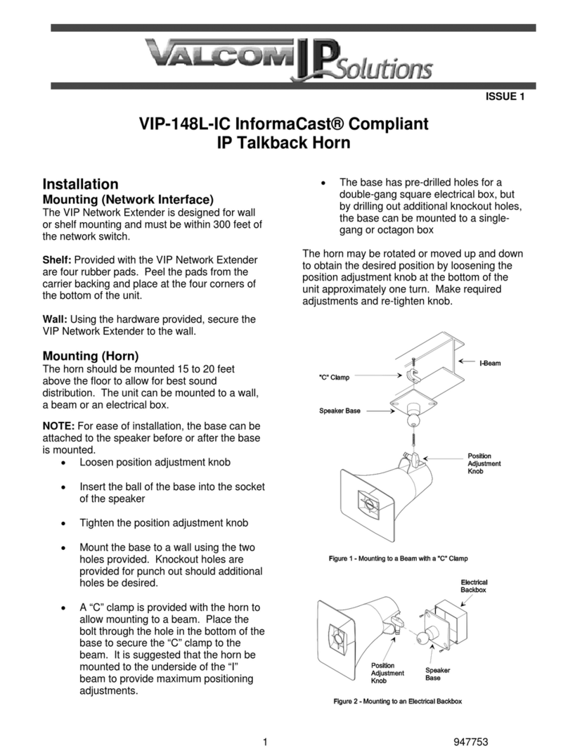
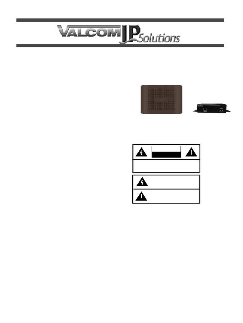
  9. Valcom VIP-148AL-SA Syn-Apps User manual

Valcom VIP-148AL-SA Syn-Apps User manual

Other Valcom Horn manuals
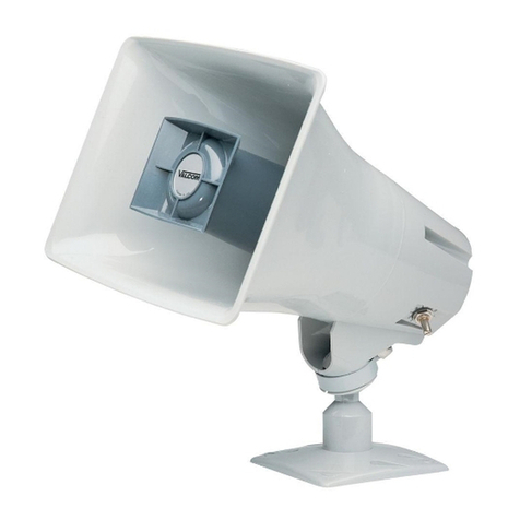
Valcom VIP-130AL-IC User manual

Valcom

Valcom VIP-130AL-IC User manual

Valcom V-1030C User manual

Valcom

Valcom V-1030C User manual

Valcom FlexHorn VIP-483-IC User manual

Valcom

Valcom FlexHorn VIP-483-IC User manual

Valcom V-1038 User manual

Valcom

Valcom V-1038 User manual

Valcom V-1069 User manual

Valcom

Valcom V-1069 User manual

Valcom V-1030C User manual

Valcom

Valcom V-1030C User manual

Valcom V-1048C User manual

Valcom

Valcom V-1048C User manual

Valcom VIP-480AL User manual

Valcom

Valcom VIP-480AL User manual

Valcom V-1050C User manual

Valcom

Valcom V-1050C User manual

Valcom FLEXHORN V-1090 User manual

Valcom

Valcom FLEXHORN V-1090 User manual

Valcom V-9945A User manual

Valcom

Valcom V-9945A User manual

Valcom VIP-130AL-SA User manual

Valcom

Valcom VIP-130AL-SA User manual

Valcom VIP-480AL-IC User manual

Valcom

Valcom VIP-480AL-IC User manual

Valcom InformaCast VIP-148L-IC User manual

Valcom

Valcom InformaCast VIP-148L-IC User manual

Valcom InformaCast VIP-480L-IC User manual

Valcom

Valcom InformaCast VIP-480L-IC User manual

Valcom V-1090 Flexhorn User manual

Valcom

Valcom V-1090 Flexhorn User manual

Valcom V-1069A User manual

Valcom

Valcom V-1069A User manual
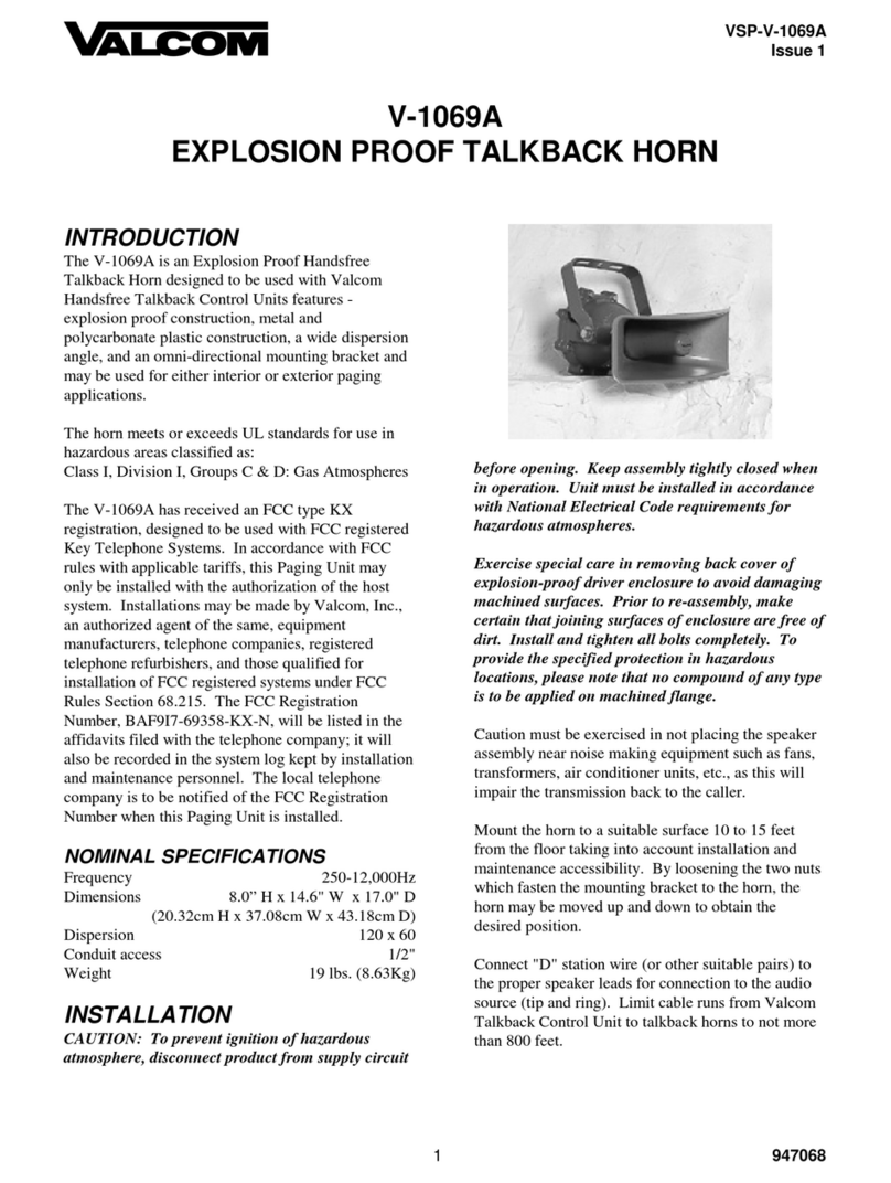
Valcom V-1038 User manual

Valcom

Valcom V-1038 User manual
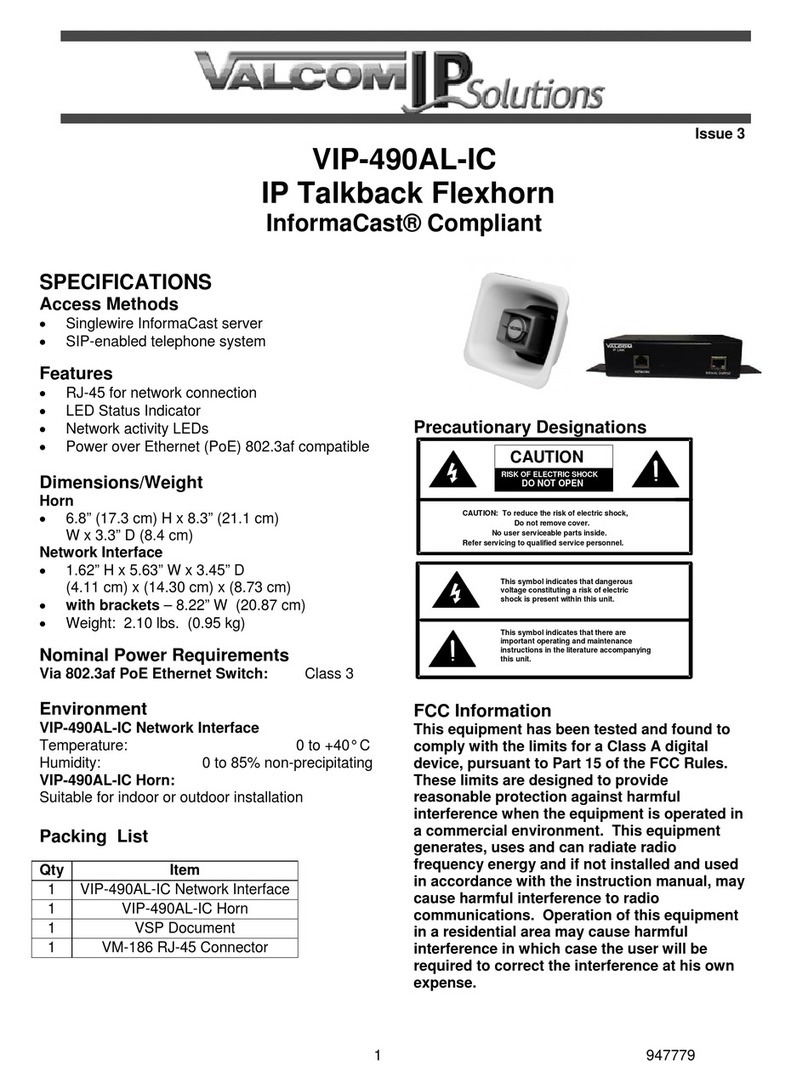
Valcom PagePac V-5331001 User manual

Valcom

Valcom PagePac V-5331001 User manual

Valcom V-1080 Flexhorn User manual

Valcom

Valcom V-1080 Flexhorn User manual
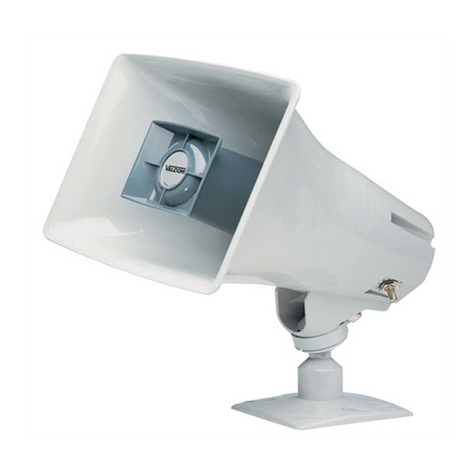
Valcom VIP-148AL-IC User manual

Valcom

Valcom VIP-148AL-IC User manual

Valcom PagePac V-5331215A User manual

Valcom

Valcom PagePac V-5331215A User manual
Valcom VIP-480AL-SA User manual

Valcom

Valcom VIP-480AL-SA User manual

Valcom VIP-130L User manual

Valcom

Valcom VIP-130L User manual

Popular Horn manuals by other brands

Klenn Air Horns JL-JK-OBA installation manual

Klenn Air Horns

Klenn Air Horns JL-JK-OBA installation manual

Vixen Horns VXO8350 installation guide

Vixen Horns

Vixen Horns VXO8350 installation guide

Elk Products 45 user manual

Elk Products

Elk Products 45 user manual
Cooper Wheelock DB3 Series specification
Cooper Wheelock

Cooper Wheelock DB3 Series specification

Altec Lansing 811B HF HORN manual

Altec Lansing

Altec Lansing 811B HF HORN manual

RF Elements UltraHorn CC Series quick start guide

RF Elements

RF Elements UltraHorn CC Series quick start guide

Edwards Signaling 869DSTR-G1 Series Installation sheet
Edwards Signaling

Edwards Signaling 869DSTR-G1 Series Installation sheet

Toa LE-M124 Specifications

Toa

Toa LE-M124 Specifications

AUSTRALIAN MONITOR MH30 brochure

AUSTRALIAN MONITOR

AUSTRALIAN MONITOR MH30 brochure

Vixen Horns VXO8805/3311C installation guide

Vixen Horns

Vixen Horns VXO8805/3311C installation guide

Federal Signal Corporation 350 Installation and maintenance instructions

Federal Signal Corporation

Federal Signal Corporation 350 Installation and maintenance instructions

Electro-Voice MH4020AC Specifications

Electro-Voice

Electro-Voice MH4020AC Specifications

Dynacord 18" Full-W Vented Bass Horn alpha B6 Specifications

Dynacord

Dynacord 18" Full-W Vented Bass Horn alpha B6 Specifications

Kleinn RAMHDOBA-6450 installation instructions

Kleinn

Kleinn RAMHDOBA-6450 installation instructions

Vixen Horns VXO8715/4124B installation guide

Vixen Horns

Vixen Horns VXO8715/4124B installation guide

Wheelock HS-24 installation instructions

Wheelock

Wheelock HS-24 installation instructions

Altec Lansing MR945A HF HORN manual

Altec Lansing

Altec Lansing MR945A HF HORN manual

Vixen Horns VXO8530/3311B installation guide

Vixen Horns

Vixen Horns VXO8530/3311B installation guide

manuals.online logo
manuals.online logoBrands
  • About & Mission
  • Contact us
  • Privacy Policy
  • Terms and Conditions

Copyright 2025 Manuals.Online. All Rights Reserved.

1 947565
CAUTION: To reduce the risk of electric shock,
Do not remove cover.
No user serviceable parts inside.
Refer servicing to qualified service personnel.
CAUTION
RISK OF ELECTRIC SHOCK
DO NOT OPEN
This symbol indicates that dangerous
voltage constituting a risk of electric
shock is present within this unit.
This symbol indicates that there are
important operating and maintenance
instructions in the literature accompanying
this unit.
Issue 1
VIP-148AL-SA
Syn-Apps® Compliant
IP Talkback Horn
INTRODUCTION
The VIP-148AL-SA Syn-Apps® Compliant IP
Talkback Horn enables two-way handsfree voice
access to a single location over an IP-based
network. The horn audio level is electronically
adjusted from the Syn-Apps server. A call switch
input connection is provided for call initiation.
Power is provided to the VIP-148AL via a Power
over Ethernet (PoE) switch meeting the 802.3af
specification.
SPECIFICATIONS
Access Methods
Syn-Apps Revolution server
SIP telephone system
Features
RJ-45 for network connection
Network activity LEDs
Power over Ethernet (PoE) 802.3af
compatible
Dimensions/Weight:
VIP-148AL-SA Horn
7.38” H x 10.0” W x 10.4” D
(18.75cm x 25.4cm x 26.42cm)
Weight: 3.70 lbs. (1.68 kg)
Network Interface
1.62” H x 5.63” W x 3.45” D
(4.11 cm) x (14.30 cm) x (8.73 cm)
with brackets –8.22” W (20.87 cm)
Weight: 2.10 lbs. (0.95 kg)
Environment
Network Interface:
Temperature: 0 to +40° C
Humidity: 0 to 85% non-precipitating
Horn:
Suitable for indoor or outdoor installation
Nominal Power Requirements
Via 802.3af (PoE) Ethernet Switch: Class 3
Precautionary Designations
FCC Information
This equipment has been tested and found to
comply with the limits for a Class A digital
device, pursuant to Part 15 of the FCC Rules.
These limits are designed to provide
reasonable protection against harmful
interference when the equipment is operated
in a commercial environment. This
equipment generates, uses and can radiate
radio frequency energy and if not installed
and used in accordance with the instruction
manual, may cause harmful interference to
radio communications. Operation of this
equipment in a residential area may cause
harmful interference in which case the user
will be required to correct the interference at
his own expense.
2 947565
INSTALLATION
Operation:
Provides talkback intercom via Network
connection to customer telephone system,
Syn-Apps Revolution server or other destination.
Interface to customer telephone system can be
via SIP registration, FXO port or FXS port
(additional equipment may be required). The
optional call button may be programmed to
initiate a call to one of the above telephone
system interfaces. When the call is answered, a
hands-free communications path is established
to the horn.
Mounting (Network Interface)
The VIP-148AL-SA Network Interface is designed
for wall or table mounting and must be within 100
meters of the network switch.
Mounting (Horn)
The VIP-148AL-SA Horn is designed for most FD
electrical box or wall mounting and must be within
300 meters of the VIP-148AL-SA Network
Interface. See NEMA OS 3-2002 sec.1.2.3.5 for
FD box specifications.
Attaching Speaker to Base
NOTE: For ease of installation, the base can be
attached to the speaker before or after the base
is mounted.
Loosen position adjustment knob
Insert the ball of the base into the socket of
the speaker
Tighten the position adjustment knob
These horns should be mounted 15 to 20 feet
above the floor to allow for best sound
distribution. The units can be mounted to a wall,
a beam or an electrical box.
A “C” clamp is provided with the horns to
allow mounting to a beam. When using the
“C” clamp for mounting, remove the signal
cable from the ball mount. Reinstall an RJ45
connector on the signal cable after mounting,
using the T568B pinout scheme.
See Figure 1.
The base has holes punched for a
double-gang square box, but by punching out
additional knockout holes, the base can be
mounted to a single-gang or octagon box
See Figure 2.
Mount the base to wall studs using the two
holes provided. Knockout holes are provided
for punch out should additional holes be
desired. See Figure 3.
The horns may be rotated or moved up and down
to obtain the desired position by loosening the
position adjustment knob at the bottom of the unit
approximately one turn. Make required
adjustments, retighten knob.
Figure 1. Mounting to a Beam with a “C” Clamp
Figure 2. Mounting to an electrical Backbox
3 947565
Figure 3. Mounting to Wall stud
Power Connections
The only method of powering a VIP-148AL-SA
Network Interface is via a Power over Ethernet
(PoE) switch or power injector meeting the
802.3af specification. Make all required signal
connections before connecting to Ethernet switch
or power injector meeting the 802.3af
specification.
Network Connection
The VIP-148AL-SA Network Interface has one
RJ-45 Ethernet network connector and one RJ-45
horn connector.
Use a standard Ethernet patch cable to connect
the VIP-148AL-SA to an Ethernet switch.
Signal Connections
Audio output connection is made from the Signal
Output. The RJ-45 connector on the horn is
connected directly to the RJ-45 Signal Output
socket on the Network Interface. If additional
length is required, any standard T568B extension
may be used. See Figure 4.
If desired, a normally-open call button may be
connected to the Blue, White/Blue pair of the
horn RJ-45 connector. The VM-186 RJ-45
connector provides easy access to these
connections.
Status Indicator Lights
The VIP-148AL-SA has 2 status indication lights
located on network jack:
Green LED: (Link) Indicates Ethernet
connection when illuminated.
Yellow LED: (Activity) Indicator flashes to
indicate network activity.
Setup
The VIP-148AL-SA will automatically acquire an
IP address (using DHCP) and connect to the
Syn-Apps Revolution server when connected to
the network and powered up. Information specific
to your application will need to be programmed
into the Revolution server. Refer to the Syn-Apps
documentation for further information. Additional
setup, if necessary, will be done using the
Valcom IP Solutions Setup Tool. The IP
Solutions Setup Tool is available for download on
the Valcom website at
www.valcom.com/vipsetuptool.
TECHNICAL ASSISTANCE
Assistance in troubleshooting is available from
the factory when problems are encountered.
Call (540) 563-2000 and press 1 for Technical
Support or visit our website at
http://www.valcom.com.
Valcom equipment is not field repairable.
Valcom, Inc. maintains service facilities in
Roanoke, VA. Should repairs be necessary,
attach a tag to the unit clearly stating your
company name, address, phone number, contact
person and the nature of the problem. Send the
unit to:
Valcom, Inc.
Repair & Return Dept.
5614 Hollins Road
Roanoke, Va. 24019-5056
WARRANTY
Warranty information may be found on our
website at www.valcom.com/warranty.
4 947565
RJ45 NETWORK
CONNECTION
SIDE
HORN SIGNAL CONNECTION
HORN
RJ45 NETWORK
CONNECTION
SIDE
STANDARD
RJ45 PATCH CABLE
(T568B)
Typical 568B
RJ-45 Jack
RJ-45
CAT 3/5/6
VM-186
RJ45
WHITE/GREEN
GREEN
WHITE/BROWN
BROWN
BROWN
BLUE
WHITE/BLUE
BLUE
WHITE/ORANGE
ORANGE
WHITE/GREEN
GREEN
WHITE/BROWN
BROWN
WHITE/BLUE
BLUE
WHITE/ORANGE
ORANGE
HORN
*The Maximum Recommended Distance
From the IP Link to the Horn is 350’.
CALL IN SWITCH
NORMAL OPEN
MOMENTARY CLOSED
(OPTIONAL)
Figure 4. Signal Connections