2 947572
INSTALLATION
Operation:
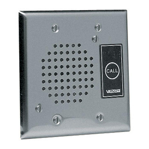
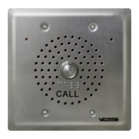
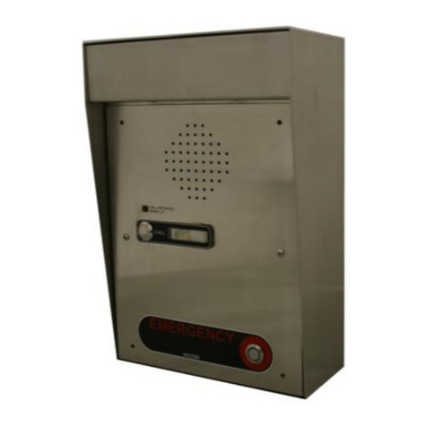
The VIP-176A-IC provides door intercom access
via network connection to customer telephone
system or stand-alone telephone set. Interface to
customer telephone system can be via SIP
registration to a voice over IP (VoIP) telephone
system, or FXO port (when used with a Valcom
Enhanced Station Port). Pressing the call button
on the door plate initiates a call to a user-
specified telephone number and the call
assurance LED on the door plate begins to flash.
When the call is answered, a hands-free
communications path is established to the door
plate, and the call assurance LED on the door
plate remains lit. An optional Smart Relay
module, VM-SRLY is available separately, which
provides one form C relay for uses such as
activating door entry equipment.
Mounting
For enhanced protection against static
electrical discharge, it is recommended the
VIP-176A-IC be installed into a grounded
electrical box.
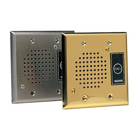
The VIP-176A-IC Doorplate is designed for
double gang FD electrical box mounting. Verify
depth of electrical box is adequate for mounting
the VIP-176A-IC. (See Figure 1)
When purchasing weatherproof box, the ground
screw should be off-center. For example, Bell
part number 5333-0 could be used.
(See Figure 2)
Power Connections
The only method of powering the VIP-176A-IC is
via a Power over Ethernet (PoE) switch or power
injector meeting the 802.3af specification.
Make all required signal connections before
connecting to Ethernet switch or power injector
meeting the 802.3af specification.
Network Connection
The VIP-176A-IC has one RJ-45 Network
connector.
Green LED: (Link) Indicates Ethernet connection
when illuminated.
Yellow LED: (Activity) Indicator flashes to
indicate network activity.
Use a standard Ethernet patch cable to connect
the NETWORK connector to an Ethernet switch.
(See Figure 3).
Figure 1.
Figure 2.
Figure 3.
