manuals.online logo
Brands
  1. Home
  2. •
  3. Brands
  4. •
  5. Valcom
  6. •
  7. Power Supply
  8. •
  9. Valcom VIP-814A User manual

Valcom VIP-814A User manual

INTR
O
The VIP-
8
allows m
o
connecte
d
SPECI
Access
PBX,
POT
S
Featur
e
RJ-4
5
4 RJ-
4 Rel
a
Gene
Front
2 RE
N
2.5m
m
Pow
e
Dimen
s
1.75
H
(4.45
c
Weig
h
Nomin
a
Input Imp
e
Input Lev
e
Output I
m
Output L
e
Relay Cu
r
Nomina
l
V
ia rear
p
Voltage:
Current:
V
ia 802.
3
802.3af:
Enviro
n
Tempera
t
Humidity:
Q
U
O
DUCTIO
N
8
14A Quad N
o
st loop start
t
d
to a manag
e
FICATIO
N
Methods
FXO Port
S
telephone s
e
s
5
for network
11 telephone
a
ys with For
m
rates Caller I
panel Status
N
m
jack for ex
t
e
r over Ether
n
s
ions/Weig
H
x 6.75" W
x
c
m H x 17.15
h
t: 1.75 lbs.
a
l Specific
a
e
dance:
e
l:
m
pedance:
e
vel:
r
rent:
l
Power Re
q
p
anel barrel
c
3
af PoE Ethe
r
n
ment
t
ure:
U
AD N
E
N
etworked St
a
t
erminal devi
c
e
d IP-based
L
N
S
et
connection
connections
m
C contacts
D Signals
/Link/
A
ctivity
t
ernal power
(
n
et 802.3af c
o
ht
x
9.5" D
cm W x 24.1
3
(0.80 kg)
a
tions
- 1
0
1 A
M
q
uirements
c
onnector:
r
net Switch:
0 to 85% no
n
V
I
P
E
TWO
R
a
tion Port
c
es to be
L
AN/WAN.
LEDs
(
optional)
o
mpatible
3
cm D)
600 Ohm
s
-10dB
m
600 Ohm
s
0
dBm nomina
M
P @ 24VD
C
24VD
C
325m
A
Class 3
0 to +40° C
n
-precipitatin
g
1
P
-814
A
R
KED S
T
s
m
s
l
C
C
A
g
Pa
c
Q
t
1
1
2
4
IN
S
NO
T
this
equ
i
a P
B
set
s
or i
n
tele
p
cus
t
a ke
inte
r
sys
t
pro
t
sys
t
cen
t
pre
v
net
w
Pre
CAUTION: To reduce
t
Do not
r
No user servi
c
Refer servicing to qua
l
CA
U
RISK OF E
L
DO
N
This symbo
voltage con
shock is pr
e
This symbo
important o
instruction
s
this unit.
A
T
ATIO
N
c
king List
t
y
2
Mountin
4
S
TALLA
T
T
E: The tele
p
manual is t
h
i
pment such
B
X or a dedi
c
s
. The VIP-8
1
n
direct conn
e
p
hone netw
o
t
omer premi
s
e
y system or
r
faced to th
e
t
em central
o
t
ected interf
a
t
em must be
t
ral office tr
u
v
ent indirect
w
ork.
cautionar
y
t
he risk of electric shock,
r
emove cover.
c
eable parts inside.
l
ified service personnel.
U
TION
L
ECTRIC SHOCK
N
OT OPEN
l indicates that dangerous
stituting a risk of electric
e
sent within this unit.
l indicates that there are
perating and maintenance
s
in the literature accompan
y
N
POR
T
Item
VIP-814
A
VSP Docum
g Brackets
W
Rubber Pa
d
T
ION
p
hone syste
h
e customer
h
as an elect
r
c
ated single
1
4A is not in
ection to th
e
o
rk. When u
s
s
e telephon
e
PBX syste
m
e
system via
o
ffice port,
w
a
ce device.
A
configured
t
u
nk confere
n
connection
y
Designa
t
9
4
y
ing
IS
S
T
A
ent
W
/ Hardware
d
s
m referred t
o
premise
r
onic key sy
s
line telepho
n
tended for
d
e
public
s
ed with a
e
system su
c
m
, these unit
s
a fully prot
e
w
hich is a ful
A
lso, the ho
s
t
o disallow
n
cing in ord
e
to the publi
c
t
ions
4
7462
S
UE 1
o
in
s
tem,
ne
d
irect
c
h as
s
are
e
cted
ly
s
t
e
r to
c
FCC In
f
This equ
i
comply
w
device,
p
These li
m
reasona
b
interfere
n
in a com
m
equipme
n
radio fre
q
and use
d
manual,
m
radio co
m
equipme
n
harmful i
will be r
e
his own
e
Mounti
n
The VIP-
8
mounting
.
Table: P
r
rubber p
a
backing
a
bottom of
Wall: Usi
n
documen
t
screw hol
3/4" deep
wood scr
e
the wall.
hardware
included)
.
to the wal
using the
the brack
e
Rack: Fo
attach th
e
VIP-814
A
VIP-814
A
See Figu
r
f
ormation
i
pment has
b
w
ith the limit
s
ursuant to
P
m
its are desi
g
b
le protectio
n
n
ce when th
e
m
ercial envi
r
n
t generate
s
q
uency ener
g
d
in accorda
n
m
ay cause
h
m
municatio
n
n
t in a resid
e
nterference
e
quired to c
o
e
xpense.
n
g
8
14A is desig
.
r
ovided with t
h
a
ds. Peel the
a
nd place at t
h
the unit
n
g the templ
a
t
, mark the lo
c
es on the wa
, at each scr
e
e
ws provided
For surfaces
appropriate
f
.
With the br
a
l, attach the
V
included har
d
e
t assembly.
llowing the a
s
e
two mounti
n
A
unit. Using r
a
A
in an availa
b
r
e 2.
Figure 1
.
b
een tested
a
s
for a Clas
s
P
art 15 of th
e
g
ned to pro
v
n
against ha
e
equipment
r
onment. T
h
s
, uses and
c
g
y and if no
t
n
ce with the
h
armful inter
f
n
s. Operatio
e
ntial area
m
in which ca
s
o
rrect the int
e
ned for wall,
t
h
e VIP-814A
pads from th
h
e four corne
a
te on last pa
g
c
ation of the
b
l
l. Drill 5/64"
e
w location a
n
to attach the
other than w
o
f
or the surfac
e
a
ckets secur
e
V
IP-814A to t
d
ware. Figur
e
s
sembly dra
w
n
g brackets t
o
a
ck screws,
m
b
le 1U rack sl
.
Wall Mount
2
a
nd found t
o
s
A digital
e
FCC Rules.
v
ide
rmful
is operated
h
is
c
an radiate
t
installed
instruction
f
erence to
n
of this
m
ay cause
s
e the user
e
rference at
t
able or rack
are four
eir carrier
r
s of the
g
e of this
b
racket
pilot holes,
n
d use the
brackets to
o
od, use
e
(not
e
ly attached
he brackets
e
1 illustrate
s
w
ing below,
o
the
m
ount the
ot.
2
o
s
Po
w
The
via
a
the
8
If th
e
pow
e
VIP-
Mak
appl
y
802.
rear
to th
If po
mak
A
tta
c
RJ-
4
plug
g
the
b
VIP-
Net
w
The
on t
h
Use
the
V
Eth
e
VIP-
Sig
On t
jack
s
bloc
k
FX
O
or s
t
via t
h
Pho
n
app
e
Fig
u
w
er Conn
e
preferred m
e
a
Power over
8
02.3af speci
e
rear panel
b
e
r, the prefer
-
324D.
e all required
ying power t
o
3af, make su
panel are m
a
e Ethernet s
w
o
wer is suppli
e
e sure all sig
n
c
h the unit to
4
5 Ethernet c
o
ging the pow
e
b
arrel conne
c
-
814A.
t
work Con
n
VIP-814A h
a
h
e front pane
a standard
E
V
IP-814A to
a
e
rnet switch i
s
-
814A will dr
a
nal Conn
e
he rear pane
s
for telepho
n
ks for relay c
o
O
Connectio
n
t
andard anal
o
h
e rear pane
l
n
e 2, Phone
3
e
ar on pins 3
u
re 2. Rack
M
e
ctions
e
thod of pow
e
Ethernet (Po
fication.
b
arrel conne
c
red power su
d
signal conn
e
o
the unit. If
p
u
re all signal
c
a
de then con
n
w
itch.
e
d via the ba
r
n
al connecti
o
the network
v
o
nnector. A
p
er supply in t
o
c
tor on the re
a
n
ection
a
s one RJ-45
l.
E
thernet patc
h
a
n Ethernet s
w
s
802.3af co
m
a
w power fro
m
e
ctions
l, the VIP-81
4
n
e connectio
n
o
nnections.
n
s: Connect l
o
o
g telephone
s
l
RJ-11 jacks
3
and Phone
and 4 of the
s
9
4
M
ount
e
ring a VIP-8
1
o
E) switch m
e
c
tor is used f
o
pply is a Val
c
e
ctions befor
e
p
owering via
c
onnections
v
n
ect the VIP-
8
r
rel connecto
o
ns are secur
e
v
ia the front
p
p
ply power b
y
o
the VIP-81
4
a
r of the
network con
n
h
cable to co
n
w
itch. If the
m
pliant the
m
it.
4
A has 4 RJ-
1
n
and 2 termi
n
o
op start FX
O
s
to the VIP-
8
labeled Pho
n
4. Tip and
R
s
e jacks.
4
7462
1
4A is
e
eting
o
r
c
om
e
v
ia the
8
14A
r,
e
.
p
anel
y
4
A via
n
ector
n
nect
1
1
n
al
O
port
8
14A
n
e 1,
R
ing
3 947462
K1 K2 K3 K4
+24V DC
1
PHONE PHONE
2 3
PHONE PHONE
4
N.O.
N.C.
COM
COM
N.C.
N.O.
N.O.
N.C.
COM
COM
N.C.
N.O.
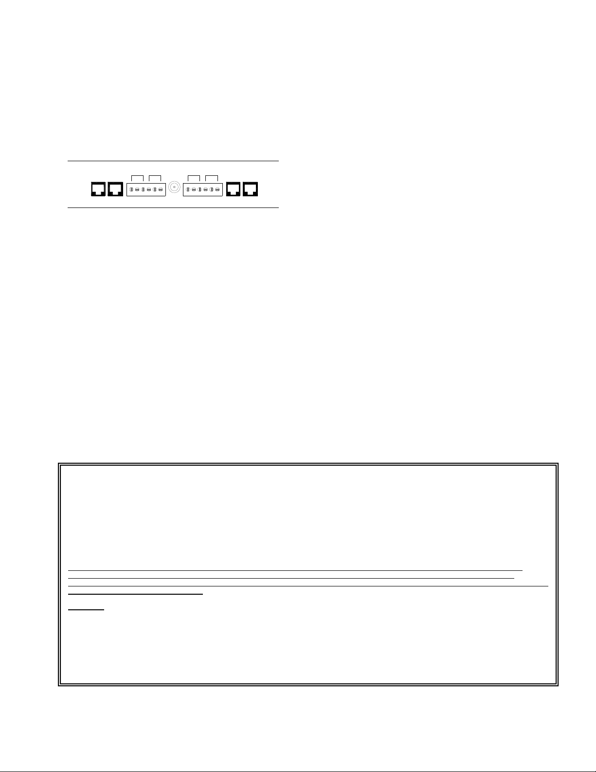
Relay Connections: Access to the four form C
relays is provided via two six pin screw terminal
blocks. The relays are labeled K1, K2, K3 and
K4. Each relay is brought out on three
terminals. The common contact (COM) is the
middle terminal with the normally closed (N.C.)
contact on the right and the normally open
(N.O.) contact on the left. Relay contacts are
rated for 1A @ 24VDC.
Rear View
Setup
Information specific to your application will need
to be programmed into the VIP-814A using a
computer. The PC used for programming
should be connected to the same subnet as the
VIP-814A. Setup will be done using the IP
Solutions Setup Tool. Download the latest
version of the free IP Solutions Setup Tool from
the Valcom web site at
www.valcom.com/vipsetuptool.
Status Indicator Lights
The VIP-814A has 3 status indication lights on
the front panel:
STATUS: Illuminates at regular intervals during
normal operation. On steady indicates unit is in
reset mode.
The network jack provides two LED indicators:
Green LED: (Link) Indicates Ethernet
connection when illuminated.
Yellow LED: (Activity) Indicator flashes to
indicate network activity.
TECHNICAL ASSISTANCE
When trouble is reported, verify power is being
supplied to the unit and there are no broken
connections. If a spare unit is available,
substitute a spare unit for the suspected
defective unit.
Assistance in troubleshooting is available from
the factory. Call (540) 563-2000 and press 1 for
Technical Support or via email at
[email protected].
When requesting assistance, you should include
all available information. General information
and troubleshooting procedures are available on
the Valcom website at www.valcom.com.
Valcom equipment is not field repairable.
Valcom, Inc. maintains service facilities in
Roanoke, VA. Should repairs be necessary,
attach a tag to the unit clearly stating your
company name, address, phone number,
contact person and the nature of the problem.
Send the unit to:
Valcom, Inc.
Repair & Return Dept.
5614 Hollins Road
Roanoke, Va. 24019-5056
.
VALCOM LIMITED WARRANTY
Valcom, Inc. warrants its products only to the original purchaser, for its own use, to be free from defects in materials and workmanship under conditions of
normal use and service for a period of one year from the date of shipment. This Limited Warranty obligation shall be limited to the replacement, repair or refund
of any such defective device within the warranty period, provided that:
1. inspection by Valcom, Inc. indicates the validity of the claim;
2. the defect is not the result of damage, misuse or negligence after the original shipment;
3. the product has not been altered in any way or repaired by others and that factory sealed units are unopened (a service charge plus parts
and labor will be applied to units defaced or physically damaged);
4. freight charges for the return of products to Valcom are prepaid;
5. all units 'out of warranty' are subject to a service charge. The service charge will cover minor repairs (major repairs will be subject to
additional charges for parts and labor).
This Limited Warranty is in lieu of and excludes all other warranties, expressed or implied and in no event shall Valcom, Inc. be liable for any
anticipated profits, consequential damages, loss of time or other losses incurred by the buyer in connection with the purchase, operation,
maintenance, installation, removal or use of the product. The maximum liability of Valcom under this warranty is limited to the purchase price of the
specific Product covered by the warranty.
Disclaimer. Except for the Limited Warranty provided herein, the product is provided “as-is” without any warranty of any kind whatsoever including, without
limitation, any WARRANTY OF MERCHANTABILITY, FITNESS FOR A PARTICULAR PURPOSE OR NON-INFRINGEMENT.
This warranty specifically excludes damage incurred in shipment. In the event a product is received in damaged condition, the carrier should be notified
immediately. Claims for such damage should be filed with the carrier involved in accordance with the F.O.B. point.
Headquarters:
Valcom, Inc.
5614 Hollins Road Roanoke, VA 24019-5056
Phone: (540) 563-2000 FAX: (540) 362-9800
4 947462

Other Valcom Power Supply manuals

Valcom VPB-260 User manual

Valcom

Valcom VPB-260 User manual

Valcom V-C6124P User manual

Valcom

Valcom V-C6124P User manual

Valcom VP-6124 User manual

Valcom

Valcom VP-6124 User manual

Valcom VP-624B User manual

Valcom

Valcom VP-624B User manual

Valcom VP-1024 User manual

Valcom

Valcom VP-1024 User manual

Valcom VP-324 User manual

Valcom

Valcom VP-324 User manual

Valcom VP-2048C User manual

Valcom

Valcom VP-2048C User manual

Valcom VP-324 User manual

Valcom

Valcom VP-324 User manual

Valcom VP-2124A User manual

Valcom

Valcom VP-2124A User manual

Valcom VP-624D User manual

Valcom

Valcom VP-624D User manual

Valcom VP6124 User manual

Valcom

Valcom VP6124 User manual

Valcom VP-2048B User manual

Valcom

Valcom VP-2048B User manual

Valcom VP-624B User manual

Valcom

Valcom VP-624B User manual

Valcom VP-2124A User manual

Valcom

Valcom VP-2124A User manual

Valcom VP-2124A-EC User manual

Valcom

Valcom VP-2124A-EC User manual

Valcom VP-6124 User manual

Valcom

Valcom VP-6124 User manual

Valcom VP-6124-P User manual

Valcom

Valcom VP-6124-P User manual

Valcom VP-412A User manual

Valcom

Valcom VP-412A User manual

Valcom VP-12124 User manual

Valcom

Valcom VP-12124 User manual

Valcom VP-2024 User manual

Valcom

Valcom VP-2024 User manual

Valcom VP-1124 User manual

Valcom

Valcom VP-1124 User manual

Valcom VP-324 User manual

Valcom

Valcom VP-324 User manual

Valcom VP-4024C User manual

Valcom

Valcom VP-4024C User manual

Valcom VP-412A User manual

Valcom

Valcom VP-412A User manual

Popular Power Supply manuals by other brands

Delta Electronics Delphi Q48DR datasheet

Delta Electronics

Delta Electronics Delphi Q48DR datasheet

Genetec Synergis IX SY-SIX-PSU-DIN-4A installation manual

Genetec

Genetec Synergis IX SY-SIX-PSU-DIN-4A installation manual

Pulsar GREEN POWER plus HADOC 3012C manual

Pulsar

Pulsar GREEN POWER plus HADOC 3012C manual

ABB PCS100 UPS-I user manual

ABB

ABB PCS100 UPS-I user manual

Dr.X Works BH1-L product manual

Dr.X Works

Dr.X Works BH1-L product manual

Siemens LOGO!Power 6EP1311-1SH13 operating instructions

Siemens

Siemens LOGO!Power 6EP1311-1SH13 operating instructions

FEAS SNT128-K operating instructions

FEAS

FEAS SNT128-K operating instructions

Honeywell TC-RPCXX1 installation guide

Honeywell

Honeywell TC-RPCXX1 installation guide

HP 6236B Operating and service manual

HP

HP 6236B Operating and service manual

Franke ZAQUA006 Installation and operating instructions

Franke

Franke ZAQUA006 Installation and operating instructions

Spellman MXR Series Installation and user guide

Spellman

Spellman MXR Series Installation and user guide

Atomic AT-1A owner's manual

Atomic

Atomic AT-1A owner's manual

Block PSR 230/24-10 manual

Block

Block PSR 230/24-10 manual

Schumacher Electric SJ1 owner's manual

Schumacher Electric

Schumacher Electric SJ1 owner's manual

Friwo FW8001 Series User instructions

Friwo

Friwo FW8001 Series User instructions

Allen-Bradley 1397 installation instructions

Allen-Bradley

Allen-Bradley 1397 installation instructions

Kontron CP3-SVE-P200DC-24V user guide

Kontron

Kontron CP3-SVE-P200DC-24V user guide

VAS PS21 Operation manual

VAS

VAS PS21 Operation manual

manuals.online logo
manuals.online logoBrands
  • About & Mission
  • Contact us
  • Privacy Policy
  • Terms and Conditions

Copyright 2025 Manuals.Online. All Rights Reserved.