2
•Short circuit protection
•UL Listed for US and Canada
•FCC Class B
•CE Mark
•LED operational indicator
•EMI filtering
•94.3% efficiency green technology
•Auto recovery overload protection
•3 second power-up delay to drive large capacitive
loads up to 40K µF
Nominal Specifications
General
Efficiency: 94.3% Min @ 1A load
90% @ 4A full load
Dimensions: 8.45"H x 4.70"W x 2.35"D
(21.46cm H x 11.94cm Wx 5.97cm D)
Weight: 3.5 lbs. (1.59 kg)
Input -VP-4124
Voltage: 115VAC
Frequency: 60 Hertz
Rated Power: 110 Watts
Full Load Line Current: 1.0A
Input -VP-4124-E
Voltage: 230VAC
Frequency: 50 Hertz
Rated Power: 110 Watts
Full Load Line Current: 0.5A
Output
Rated Power: 100 Watts
Voltage: 24 Volts
Current: 4 Amps, 2 -2A outputs
Fusing: Two -2A Auto-reset polyswitch fuses
Ripple & Noise: Less than 0.2% RMS
Environmental
Operating Temperature: 0 to +40oC
Storage Temperature: -40Coto +85oC
Cooling: Free Air Convection
Humidity: 10 to 90% (non-condensing)
Shock: 10 G
Precautionary Notes:
INSTALLATION
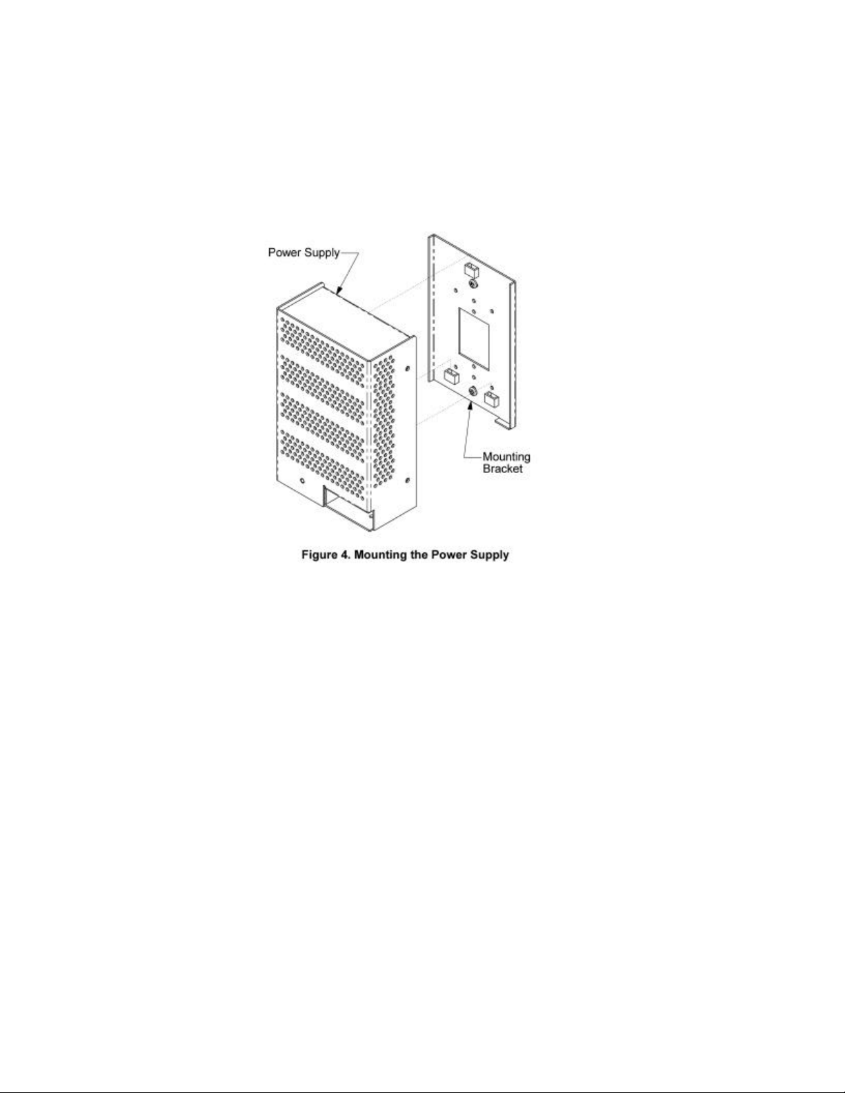
Mounting
The VP-4124 and VP-4124-E are designed for wall
mounting only. The unit should be mounted within 7
feet of an AC receptacle.
Screw mounting plate to wall and position power
supply on mounting plate via the mounting slots.
See pages 5 and 6 for mounting instructions.
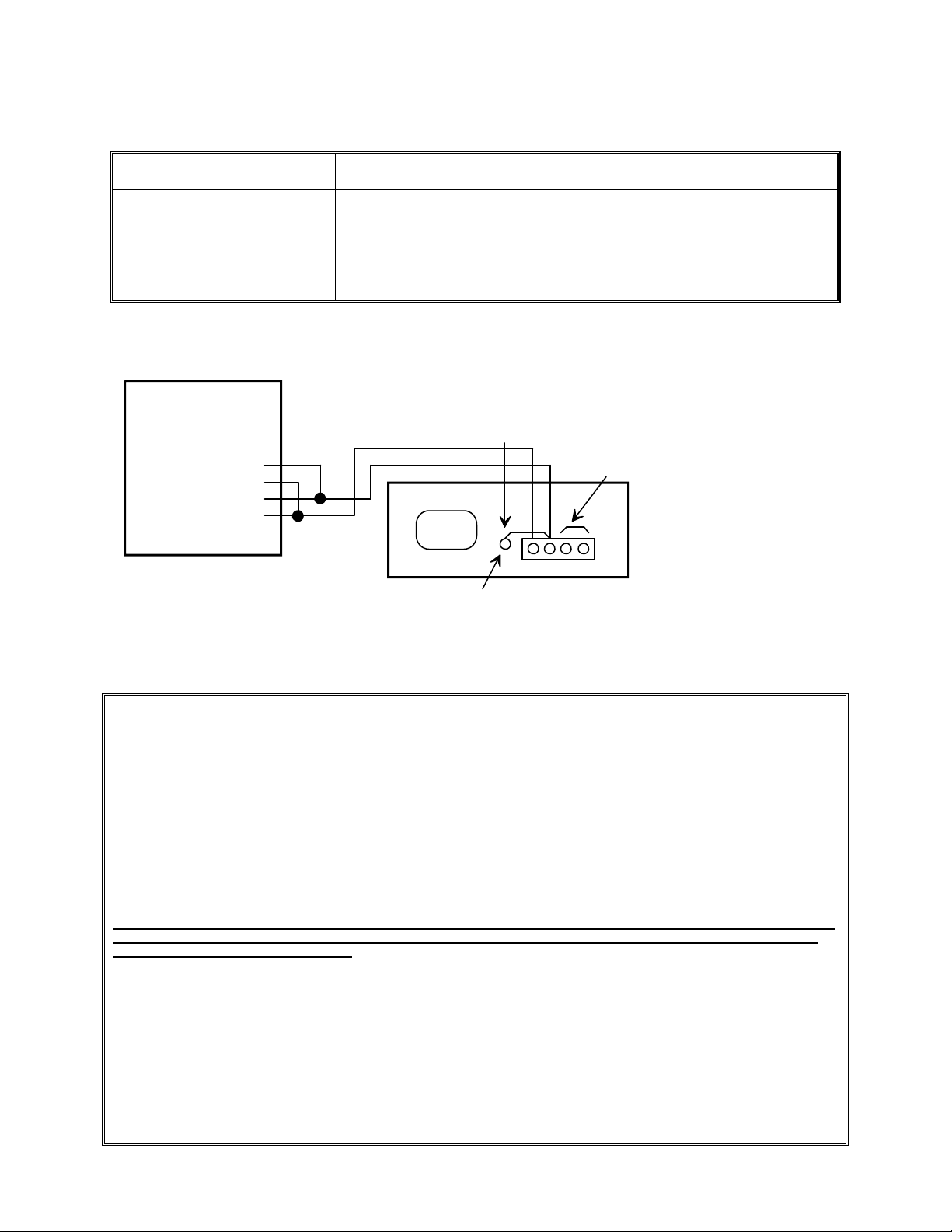
Connections
•Connections to Valcom page control units are
shown in Figure 1.
•When using the VP-4124 or VP-4124-E as a
-24VDC power supply with Valcom page
equipment, a strap may be added from the local
ground terminal to both of the "+" outputs to
provide an AC ground reference.
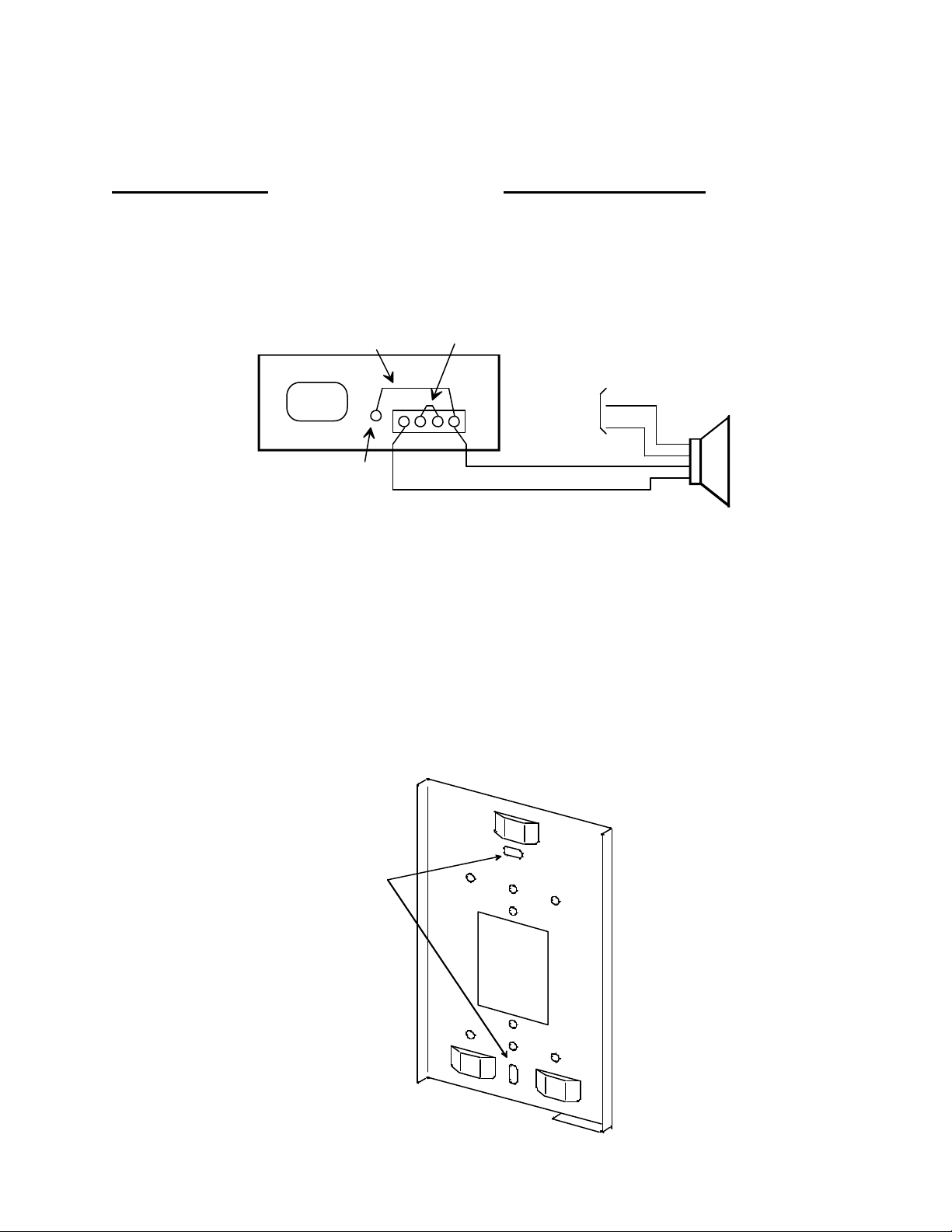
•When installing Valcom one-way amplified horns,
connect the white and black wires of the horn to
the power supply "-" and "+" terminals
respectively.
•When installing Valcom one-way speakers,
connect the "-24VDC" and "GND" terminals of
the speaker to the "-" and "+" terminals
respectively.
•Plug power supply into wall outlet.
•Power supply activates after 3 seconds delay.
NOTE: Each -24VDC screw terminal is fused by a 2
Amp polyswitch automatic. Therefore, when
connecting equipment to this power supply, the load
should be distributed between the (2) 2 Amp output
terminals (within 1.5 Amps) and each load should
not exceed 2 Amps.
TECHNICAL ASSISTANCE
When trouble is reported, verify the unit is properly
connected and there are no broken connections
leading to this unit. Assistance in troubleshooting is
available from the factory. When calling, you should
have a VOM and a test set and call from the job site.
Call (540) 563-2000 for Technical Support or call (540)
767-1555 for Valcom 24-hour Faxback System or visit
our website at http://www.valcom.com.
Valcom equipment is not field repairable. Valcom, Inc.
maintains service facilities in Roanoke, VA. Should
repairs be necessary, attach a tag to the unit clearly
stating company name, address, phone number,
contact person and the nature of the problem. Send
the unit to: Valcom, Inc.
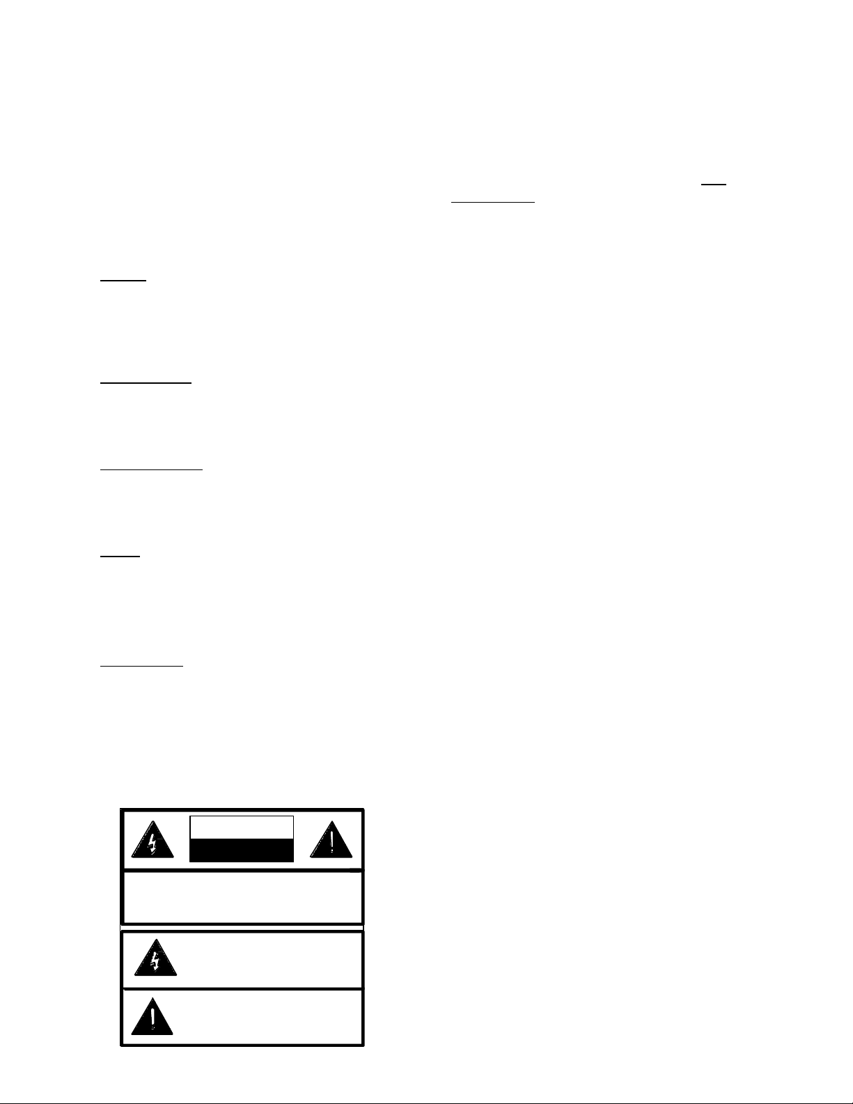
CAUTION: To reduce the risk of electric shock,
Donotremovecover.
No user serviceable parts inside.
Refer servicing to qualified service personnel.
This symbol indicates that dangerous
voltageconstituting a risk of electric
shock is present within this unit.
This symbol indicates that there are
important operating and maintenance
instructions in the literature accompanying
this unit.
CAUTION
RISK OF ELECTRIC SHOCK
DONOT OPEN