Valentin Compa II Series User manual

COMPA II
Operating Manual

Copyright by Carl Valentin GmbH / 7952005B.0715
Information on the scope of delivery, appearance, performance,
dimensions and weight reflect our knowledge at the time of printing.
We reserve the rights to make modifications.
All rights, including those regarding the translation, are reserved.
No part of this document may be reproduced in any form (print,
photocopy or any other method) or edited, copied or distributed
electronically without written permission from Carl Valentin GmbH.
Due to the constant further development of our devices discrepancies
between manual and device can occur.
Please check www.carl-valentin.de for the latest update.
Trademarks
All named brands or trademarks are registered brands or registered
trademarks of their respective owners and may not be separately
labelled. It must not be concluded from the missing labelling that it is
not a registered brand or a registered trademark.
Carl Valentin label printers comply with the following safety guidelines:
CE EG Low-Voltage Directive (2006/95/EC)
EG Electromagnetic Compatibility Directive (2004/108/EC)
Carl Valentin GmbH
Postfach 3744
78026 Villingen-Schwenningen
Neckarstraße 78 – 86 u. 94
78056 Villingen-Schwenningen
Phone
Fax
+49 (0)7720 9712-0
+49 (0)7720 9712-9901
E-Mail
Internet
www.carl-valentin.de

Compa II series Table of contents
07.15 Operating manual 3
Table of contents
Table of contents.............................................................................. 3
1Important notes ..................................................................... 5
1.1Intended use............................................................................ 5
1.2Environmentally-friendly disposal............................................ 6
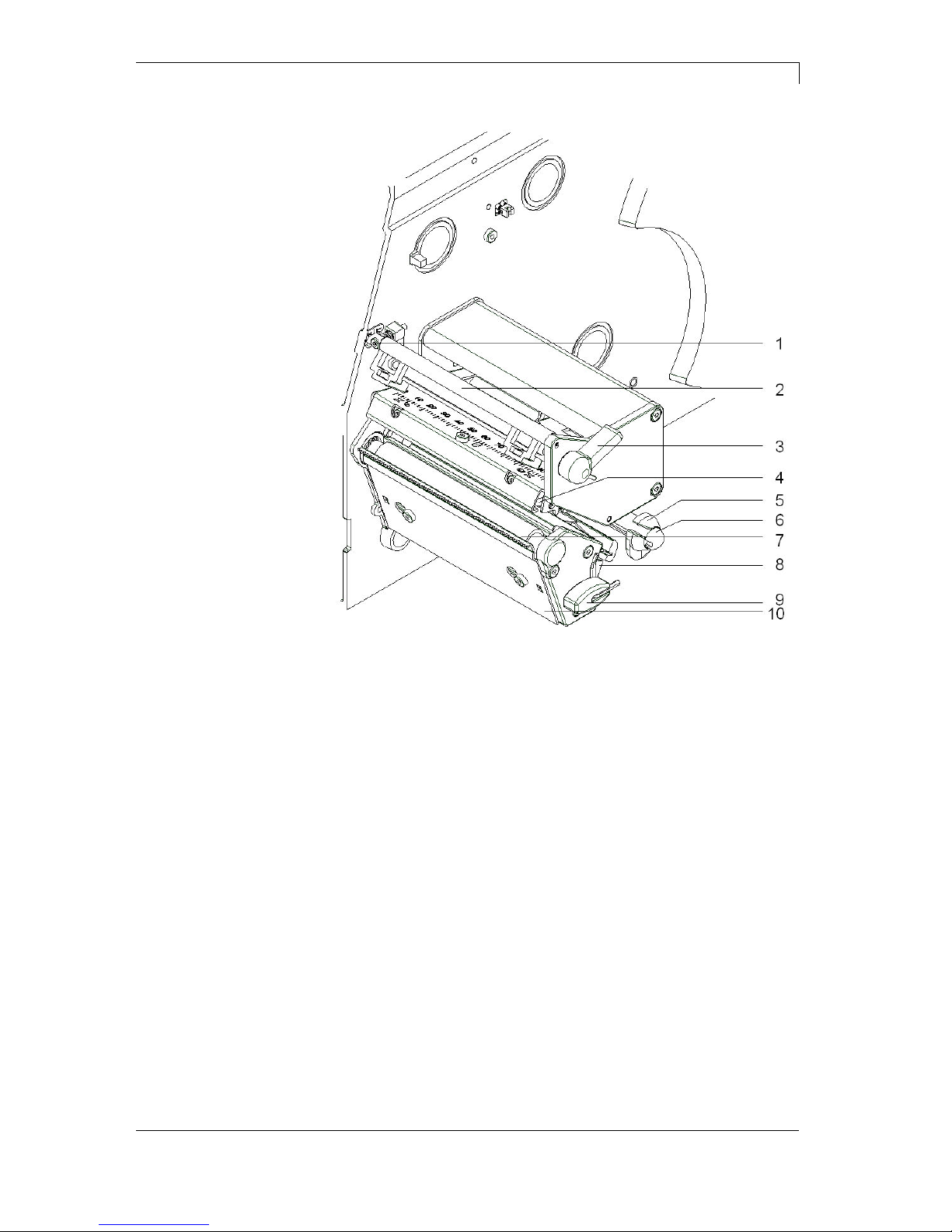
1.3Assembly drawings.................................................................. 6
2Safety notes ........................................................................... 9
2.1Warnings ................................................................................. 9
2.2Operating conditions.............................................................. 10
3Technical data...................................................................... 15
3.1Control inputs and outputs .................................................... 18
3.2Plug & Play ............................................................................ 23
4Installation............................................................................ 25
4.1Setting up the label printer .................................................... 25
4.2Connecting the label printer .................................................. 26
4.3Switching the label printer on and off .................................... 26
4.4Initiation of the label printer ................................................... 27
5Loading media ..................................................................... 29
5.1Loading label roll ................................................................... 29
5.2Removing wound roll............................................................. 35
5.3Loading fanfold labels ........................................................... 36
5.4Loading transfer ribbon ......................................................... 37
5.5Setting feed path of transfer ribbon....................................... 38
5.6Removing and/or installing rewind guide plate...................... 39
6Function menu..................................................................... 41
6.1Operation panel ..................................................................... 41
6.2Menu structure....................................................................... 42
6.3Print settings.......................................................................... 46
6.4Label layout ........................................................................... 47
6.5Device settings ...................................................................... 49
6.6Network ................................................................................. 52
6.7Remote console..................................................................... 52
6.8Interface................................................................................. 53
6.9Emulation............................................................................... 54
6.10Date & Time........................................................................... 55
6.11Service functions ................................................................... 56
6.12Main menu............................................................................. 58
7Options ................................................................................. 59
7.1Cutter..................................................................................... 59
7.2Dispenser I/O......................................................................... 61
7.3Label applicator ..................................................................... 65
7.4WLAN .................................................................................... 69
8Compact Flash Card / USB Memory Stick ........................ 71
8.1General Information............................................................... 71
8.2Display Structure ................................................................... 71
8.3Navigation.............................................................................. 72
8.4Define User Directory ............................................................ 73
8.5Load Layout........................................................................... 74
8.6File Explorer .......................................................................... 75
8.7Firmware Update ................................................................... 80
8.8Filter....................................................................................... 80

Table of contents Compa II series
4 Operating manual 07.15
9Maintenance and cleaning.................................................. 81
9.1General cleaning ................................................................... 82
9.2Cleaning the printer roller ...................................................... 82
9.3Cleaning the printhead .......................................................... 82
9.4Cleaning the label photocell .................................................. 83
9.5Replacing the printhead ........................................................ 85
9.6Replacing the print roller and rewind assist roller ................. 87
10Error correction ................................................................... 89
11Additional information ........................................................ 99
11.1Column printing ..................................................................... 99
11.2Hotstart ................................................................................ 100
11.3Password............................................................................. 102
11.4Backfeed/Delay ................................................................... 104
11.5Photocells ............................................................................ 106
12Index ................................................................................... 107

Compa II series Important notes
07.15 Operating manual 5
1 Important notes
The label printer can be used in thermal as well as in thermal transfer
applications.
The label printer is equipped with 8 vector, 6 bitmap and 6
proportional fonts. It can be printed inverse, in italic format or 90
degrees turned fonts.
The handling of our durable label printer is easy and comfortable. The
printer settings are made with the keys of the foil keyboard. At each
time the graphic display shows the current status.
By the use of a 32 Bit processor and a large main memory of 16MB
also for large labels (6000 mm) a fast print is possible.
An enormously high print quality is obtained by most modern
printhead technology.
By a new-developed electronics a maximum print speed of up to 200
mm/s can be achieved.
As default, printers of this series are equipped with a parallel, serial,
USB and Ethernet interface. Additionaly, the label printer is equipped
with an USB Host that permits the connection of an external USB
keyboard and/or an USB memory stick. The label printer automatically
recognizes by which interface it is controlled.
Time-saving printer update is possible by interface.
Thanks to the large number of options the label printer can be
adapted to each task.
1.1 Intended use
The label printer is a state-of-the-art device which complies with the
recognized safety-related rules and regulations. Despite this, a danger
to life and limb of the user or third parties could arise and the label
printer or other property could be damaged while operating the device.
The label printer may only be used while in proper working order and
for the intended purpose. Users must be safe, aware of potential
dangers and must comply with the operating instructions. Faults, in
particular those which affect safety, must be remedied immediately.
The label printer is solely intended to print suitable media which have
been approved by the manufacturer. Any other or additional use is not
intended. The manufacturer/supplier is not liable for damage resulting
from misuse. Any misuse is at your own risk.
Intended used includes heeding the operating manual, including the
maintenance recommendations/regulations specified by the
manufacturer.

Important notes Compa II series
6 Operating manual 07.15
1.2 Environmentally-friendly disposal
Manufacturers of B2B equipment are obliged to take back and
dispose of old equipment that was manufactured after 13 August
2005. As a principle, this old equipment may not be delivered to
communal collecting points. It may only be organised, used and
disposed of by the manufacturer. Valentin products accordingly
labelled can therefore be returned to Carl Valentin GmbH.
This way, you can be sure your old equipment will be disposed of
correctly.
Carl Valentin GmbH thereby fulfils all obligations regarding timely
disposal of old equipment and facilitates the smooth reselling of these
products. Please understand that we can only take back equipment
that is sent free of carriage charges.
Further information on the WEEE directive is available on our website
www.carl-valentin.de.
1.3 Assembly drawings
Figure 1
1 = Label unwinding roll
2 = Label guiding
3 = Transfer ribbon unwinding roll
4 = Transfer ribbon rewinding roll
General view

Compa II series Important notes
07.15 Operating manual 7
Figure 2
01 = Adjusting screw for transfer ribbon regulating shaft
02 = Transfer ribbon for regulating shaft
03 = Printhead lock
04 = Printhead
05 = Label material guiding
06 = Return pulley
07 = Printer roller
08 = Label photocell handhold
09 = Allan key
10 = Tear-off edge
Print mechanics

Important notes Compa II series
8 Operating manual 07.15
Figure 3
1 = Switch On/Off
2 = Power supply
3 = Plug-in for CF card
4 = USB interface
5 = Serial interface RS-232
6 = Ethernet 10/100 interface
7 = USB host for USB keyboard and USB memory stick
8 = Parallel interface for Centronics
9 = External input/output (option)
Printer rear
6.1 - LED orange
6.1 - Lighting = Connection active
6.1 - Flashing = Data transfer
6.1 - Off = No connection
6.2 - LED green
6.2 - Lighting = Speed 100 MBit
6.2 - Off = Speed 10 MBit

Compa II series Safety notes
07.15 Operating manual 9
2 Safety notes
The printer is designed for power supply systems from 110-230 V.
Connect the label printer only to electrical outlets with a ground
contact.
Couple the label printer to devices using extra low voltage only.
Before making or undoing connections, switch off all devices involved
(computer, printer, accessories etc.).
Operate the label printer in a dry environment only and do not get it
wet (sprayed water, mist etc.).
If the label printer is operated with the cover open, ensure that
clothing, hair, jewellery and similar personal items do not contact the
exposed rotating parts.
The print unit can get hot during printing. Do not touch the printhead
during operation. Cool down the print unit before changing material,
removal or adjustment.
Carry out only the actions described in these operating instructions.
Any work beyond this may only be performed by the manufacturer or
upon agreement with the manufacturer.
Unauthorized interference with electronic modules or their software
can cause malfunctions.
Other unauthorized work or modifications to the direct print module
can endanger operational safety.
Always have service work done in a qualified workshop, where the
personnel have the technical knowledge and tools required to do the
necessary work.
There are warning stickers on the direct print modules that draw your
attention to dangers. Therefore the warning stickers are not to be
removed as then you and others cannot be aware of dangers and may
be injured.
DANGER!
Danger to life and limb from power supply!
Do not open the casing.
2.1 Warnings
Warnings are presented with three signal words for the different levels
of danger.
DANGER identifies an extraordinarily great and immediate danger
which could lead to serious injury or even death.
WARNING identifies a possible danger would could lead to serious
bodily injury or even death if sufficient precautions are not taken.
CAUTION indicates a potentially dangerous situation which could lead
to moderate or light bodily injury or damage to property.

Safety notes Compa II series
10 Operating manual 07.15
2.2 Operating conditions
Before initial operation and during operation these operating conditions
have to be observed to guarantee save and interference-free service
of our printers.
Therefore please carefully read these operating conditions.
Shipment and storage of our printers are only allowed in original
packing.
Installation and initial operation of printer is only allowed if operating
conditions were fulfilled.
Initial operation, programming, operation, cleaning and service of our
printers are only recommended after careful study of our manuals.
Operation of printer is only allowed by especially trained persons.
NOTICE!
Perform trainings regularly.
Content of the training are chapter 2.2 (Operating conditions),
chapter 5 (Loading media) and chapter 9 (Maintenance and
cleaning).
These indications are also valid for someone else's equipment
supplied by us.
Only use original spare and exchange parts.
Please contact the manufacturer with respect to spare/wear parts.
CPU of printer is equipped with a lithium battery (type CR 2032) for
which the battery regulation is to apply. This regulation plans that
unloaded batteries have to be given to used battery collecting
containers of trade and public carries. In case that batteries were not
completely discharged you have to make arrangements for short-
circuits. At a shutdown of printer the battery has to be disposed in
either case separately from printer.
DANGER!
Danger of life by explosion!
Use non-conducting tools.
The installation place of printer should be even, free of vibration and
currents of air are to be avoided.
The printers have to be installed to ensure optimal operation and
servicing.
Instructions for
lithium battery
Conditions for
installation place

Compa II series Safety notes
07.15 Operating manual 11
The installation of the power supply to connect our printers has to be
effected according to the international rules and regulations,
especially the recommendations of one of the three following
commissions:
International Electronic Commission (IEC)
European Committee for Electro technical Standardisation
(CENELEC)
Verband Deutscher Elektrotechniker (VDE)
Our printers are constructed according to VDE and have to be
connected to a grounded conductor. The power supply has to be
equipped with a grounded conductor to eliminate internal interfering
voltage.
Power line voltage and power line frequency: See type plate
Allowable tolerance of power line voltage:
+6% … −10% of nominal value
Allowable tolerance of power line frequency:
+2% … −2% of nominal value
Allowable distortion factor of power line voltage: <=5%
In case your net is infected (e.g. by using thyristor controlled
machines) anti-interference measures have to be taken. You can use
one of the following possibilities:
Provide separate power supply to our printers.
In case of problems please connect capacity-decoupled isolation
transformer or similar interference suppressor in front of our
printers.
Emitted interference according to EN 61000-6-3: 2007
industrial sector
Interference voltage to wires according to EN 55022: 09-2003
Interference field power according to EN 55022: 09-2003
System perturbation according to EN 61000-3-2: 09-2006
Flicker according to EN 61000-3-3: 1955 + A1:2001 + A2:2005
Installation of
power supply
Technical data of
power supply
Anti-Interference
measures:
Stray radiation and
immunity from
disturbance

Safety notes Compa II series
12 Operating manual 07.15
Immunity to interference according to EN 61000-6-2: 2005
industrial sector
Stray radiation against discharge of static electricity according to
EN 61000-4-2: 12-2001
Electromagnetic fields according to EN 61000-4-3: 11-2003,
ENV 50204: 03-1995
Fast transient burst according to EN 61000-4-4: 07-2005
Surge according to EN 61000-4-5: 12-2001
High-frequency tension according to EN 61000-4-6: 12-2001
Voltage interruption and voltage drop according to EN 61000-4-
11: 02-2005
NOTICE!
This is a machine of type A. This machine can cause
interferences in residential areas; in this case it can be required
from operator to accomplish appropriate measures and be
responsible for it.
All connecting lines have to be guided in shielded lines. Shielding has
to be connected on both sides to the corner shell.
It is not allowed to guide lines parallel to power lines. If a parallel
guiding cannot be avoided a distance of at least 0.5 m has to be
observed.
Temperature of lines between: −15 … +80 °C.
It is only allowed to connect devices which fulfil the request 'Safety
Extra Low Voltage' (SELV). These are generally devices which are
checked corresponding to EN 60950.
The data cables must be completely protected and provide with metal
or metallised connector housings. Shielded cables and connectors are
necessary, in order to avoid radiant emittance and receipt of electrical
disturbances.
Allowable lines
Shielded line: 4 x 2 x 0,14 mm² ( 4 x 2 x AWG 26)
6 x 2 x 0,14 mm² ( 6 x 2 x AWG 26)
12 x 2 x 0,14 mm² (12 x 2 x AWG 26)
Sending and receiving lines have to be twisted in pairs.
Maximum line length: with interface V 24 (RS-232C) - 3 m (with
shielding)
with Centronics - 3 m (with shielding)
with USB - 5 m
with Ethernet - 100 m
Stray radiation and
immunity from
disturbance
Connecting lines to
external machines
Installation of
data lines

Compa II series Safety notes
07.15 Operating manual 13
To avoid inadmissible heating, free air convection has to be ensured.
Protection according IP: 20
Ambient temperature °C (operation): Min. +5 Max. +35
Ambient temperature °C (storage): Min. −20 Max. +60
Relative air humidity % (operation): Max. 80
Relative air humidity % (storage): Max. 80
(bedewing of printers not allowed)
We do not take any responsibility for damage caused by:
Ignoring our operating conditions and operating manual.
Incorrect electric installation of environment.
Building alterations of our printers.
Incorrect programming and operation.
Not performed data protection.
Using of not original spare parts and accessories.
Natural wear and tear.
When (re)installing or programming our printers please control the
new settings by test running and test printing. Herewith you avoid
faulty results, reports and evaluation.
Only specially trained staff is allowed to operate the printers.
Control the correct handling of our products and repeat training.
We do not guarantee that all features described in this manual exist in
all models. Caused by our efforts to continue further development and
improvement, technical data might change without notice.
By further developments or regulations of the country illustrations and
examples shown in the manual can be different from the delivered
model.
Please pay attention to the information about admissible print media
and the notes to the printer maintenance, in order to avoid damages
or premature wear.
We endeavoured to write this manual in an understandable form to
give and you as much as possible information. If you have any queries
or if you discover errors, please inform us to give us the possibility to
correct and improve our manual.
Air convection
Limit values
Guarantee


Compa II series Technical data
07.15 Operating manual 15
3 Technical data
Compa II
103/8 T
Compa II
104/8
Compa II
106/12
Compa II
106/24
Compa II
108/12 T
Compa II
162/12
Compa II
162/12 T
Print resolution 203 dpi 203 dpi 300 dpi 600 dpi 300 dpi 300 dpi 300 dpi
Max. print speed 200 mm/s 200 mm/s 200 mm/s 150 mm/s 200 mm/s 150 mm/s 150 mm/s
Print width 104 mm 104 mm 105.7 mm 105.6 mm 108.4 mm 162.6 mm 162.6 mm
Passage width 116 mm 116 mm 116 mm 116 mm 116 mm 176 mm 176 mm
Printhead Flat Type
1
Flat Type
2
Flat Type
2
Flat Type
2
Flat Type
1
Flat Type
2
Flat Type
1
Labels
Labels, continuous rolls
or fan-fold
paper, cardboard, textile, synthetics
Max. material weight max. 220 g/m² (larger on demand)
Min. label width 12 mm
Min. label height
Standard 5 mm
Cutter/dispenser mode 25 mm
Max. label height
(larger on demand)
6000 mm 6000 mm 3000 mm 750 mm 3000 mm 2000 mm 2000 mm
Max. roll diameter
Internal unwinder 200 mm
Internal rewinder 145 mm (option)
Core diameter 40 mm / 75 mm (option)
Winding outside or inside
Label sensor transmission and reflexion from below
Transfer ribbon
Ink outside or inside
Max. roll diameter Ø 80 mm
Core diameter 25.4 mm / 1″
Max. ribbon length 300 m
Max. width 110 mm / 170 mm (Compa II 162)
Dimensions (mm)
Width x height x depth 242 x 274 x 446 / 302 x 274 x 446 (Compa II 162)
Weight 10 kg / 14 kg (Compa II 162)
Electronics
Processor High Speed 32 Bit
RAM 16 MB / 64 MB (on demand)
Slot for Compact Flash card Type I
Battery cache for Real-Time clock (storage of data with shut-down)
Warning signal acoustic signal when error
Interfaces
Serial RS-232C (up to 115200 Baud)
Parallel Centronics (SPP)
USB 2.0 High Speed Slave
Ethernet 10/100 Base T, LPD, RawIP-Printing, DHCP, HTTP, FTP
2 x USB Master connection for external USB keyboard and memory stick
WLAN (option) card 802.11b/g WEP/WPA PSK (TKIP)
Operation data
Power supply 110-230 V / 50-60 Hz
Max. power consumption max. 150 VA
Operating temperature 5 … 35 °C
Humidity max. 80% (non-condensing)
1for thermal direct
2for thermal transfer

Technical data Compa II series
16 Operating manual 07.15
Operation panel Compa II
103/8 T
Compa II
104/8
Compa II
106/12
Compa II
106/24
Compa II
108/12 T
Compa II
162/12
Compa II
162/12 T
Keys test print, function menu, quantity,
CF Card, feed, enter, 4 x cursor
LCD display graphic display 132 x 64 Pixel
white backlight
Settings
date, time, shift times
11 language settings (others on demand)
label and device parameters, interfaces,
password protection, variables
Monitoring
Stop printing if end of ribbon / end of labels / printhead open
Status report extensive status print with information about settings
e.g. print length counter, runtime counter,
photocell interface and network parameters
printout of all internal fonts and all supported bar codes
Fonts
Font types 6 Bitmap fonts
8 Vector fonts/TrueType fonts
6 proportional fonts
other fonts on demand
Character sets Windows 1250 up to1257, DOS 437, 850, 852, 857, UTF-8
all West and East European Latin, Cyrillic, Greek and
Arabic (option) characters are supported
other character sets on demand
Bitmap fonts size in width and height 0,8-5,6
zoom 2-9
orientation 0°, 90°, 180°, 270°
Vector fonts/TrueType fonts size in width and height 1-99 mm
variable zoom
orientation 360° in steps of 90°
Font attributes depending on character font
bold, Italic, Inverse, Vertical
Font width variable
Bar codes
1D bar codes CODABAR, Code 128, Code 2/5 interleaved, Code 39,
Code 39 extended, Code 93, EAN 13, EAN 8, EAN ADD ON,
GS1-128, Identcode, ITF 14, Leitcode, Pharmacode,
PZN 7 Code, PZN 8 Code, UPC-A, UPC-E
2D bar codes Aztec-Code, CODABLOCK F, DataMatrix, GS1 DataMatrix, MAXICODE, PDF 417, QR Code
Composite bar codes GS1 DataBar Expanded, GS1 DataBar Limited,
GS1 DataBar Omnidirectional, GS1 DataBar Stacked,
GS1 DataBar Stacked Omnidirectional, GS1 DataBar Truncated
all bar codes are variable in height, module width and ratio.
orientation 0°, 90 °, 180° and 270°.
Optionally with check digit and human readable line.
Software
Configuration ConfigTool
Process control NiceLabel
Label software Labelstar Office Lite
Labelstar Office
Windows driver Windows XP® 32/64 Bit
Windows Vista® 32/64 Bit
Windows 7® 32/64 Bit
Windows 8® 32/64 Bit
Windows 8.1® 32/64 Bit
Windows Server 2003® (R2) 32/64 Bit
Windows Server 2008® 32/64 Bit
Windows Server 2008® (R2) 64 Bit
Windows Server 2012® 32/64 Bit
Windows Server 2012® (R2) 64 Bit

Compa II series Technical data
07.15 Operating manual 17
Tear-off edge
Real time clock with printout date and time
Automatic daylight saving time
Storage of data with shut-down
Variables: link field, counter, date/time, currency and shift
variable, CF data
Integrated unwinder
(max. outer diameter 180 mm
Thermal and thermal transfer version
USB host for connection of an external USB keyboard and an
USB memory stick
Ethernet interface
CVPL protocol and ZPL II® protocol
Label photocell
(transmission and reflexion from below)
Slot for CF card
Windows printer driver on CD ROM
Labelstar Office Lite on CD ROM
Cutting unit
External rewinder for labels
External rewinder for backing paper
Unwinder
WLAN interface
Dispenser I/O
Standard equipment
Optional equipment

Technical data Compa II series
18 Operating manual 07.15
3.1 Control inputs and outputs
By means of a maximum of 16 control inputs and outputs which, in the
following, are also referred to as ports, different functions of the printer
system can be triggered and operating states can be displayed.
The ports are provided by means of a D-Sub bushing (26pin HD) at
the rear panel of the printer system and are galvanically isolated from
protective earth (PE) by means of an optocoupler semi-conductor
route.
Each port can be configured as input and as output. This function
however, is predefined in the printer software and cannot be changed
by the user.
The following parameters can be changed and set by using the menu:
debounce times and high or low active.
Figure 4
Printer, internal
circuitry

Compa II series Technical data
07.15 Operating manual 19
Figure 5
Port 1 to Port 16 = Assignment for I/O Profile 'Std_Label'
Identification Pin Description / Function
Port 1 10 Print start and cut (Input)
Port 2 1 Reprint last printed label (Input)
Port 3 11 Counter Reset (Input)
Port 4 2 Option applicator only:
Start application (Input)
Port 5 12 Error reset (Input)
Port 6 3 No function
Port 7 13 No function
Port 8 4 No function
Port 9 15 Error (Output)
Port 10 6 Print order activ (Output)
Port 11 16 Dispenser photocell:
Label exists at dispenser photocell (Output)
Port 12 7 Single print (Output)
Port 13 17 Ready (Output)
Port 14 8 Option applicator only:
Ready for application (Output)
Port 15 18 No function
Port 16 9 Prior warning for transfer ribbon end (Output)
COM/VDC
for Inputs
19 Common reference potential of all control inputs. 'COM/VDC for
Inputs' is usually connected with the (-) terminal of the control voltage
and the control inputs are switched to active (+).
By means of the option '2nd LED', 'COM/VDC for Inputs' can
optionally be connected with the (+) terminal of the control voltage.
Then, the control inputs are switched to active (-).
VDC for
Outputs
20 Common supply connection of all control outputs. 'VDC for Outputs'
must be connected with the (+) terminal of the control voltage.
Never leave 'VDC for Outputs' open even if no output is used.
COM for
Outputs
5,14
21,22
Common reference potential of all control outputs. 'COM for Outputs'
must be connected with the (-) terminal of the control voltage.
Never leave 'COM for Outputs' open even if no output is used.
GND-PE 23,24 'GND-PE' is the reference potential of the '+5 VDC EXT' and '+24
VDC EXT' voltages provided by the printer system.
'GND-PE' is printer internally connected with protective earth (PE).
Configuration of
D-Sub socket

Technical data Compa II series
20 Operating manual 07.15
Identification Pin Description / Function
+ 5 VDC
EXT
25 5 Volt DC output for external use. Max. 1 A.
This voltage is provided from direct print module and can be used e.g. as
control voltage. Never apply any external voltage to this output.
+ 24 VDC
EXT
26 24 Volt DC output for external use. Max. 1 A.
This voltage is provided from direct print module and can be used e.g. as
control voltage. Never apply any external voltage to this output.
Plug Connector
Type D-Sub connector High Density
26-pin. / connector
Manufacturer W+P-Products
Reference number 110-26-2-1-20
Output Voltages (connected with GND-PE)
+ 24 V / 1 A Fuse: Polyswitch / 30 V / 1 A
+ 5 V / 1 A Fuse: Polyswitch / 30 V / 1 A
Port 1 - 15
Input
Tension 5 VDC … 24 VDC
Impedance 47Ω+ (100nF || 10 kΩ)
Output
Tension 5 VDC … 24 VDC
Impedance 47Ω+ (100nF || 10 kΩ|| 47Ω)
Current max. High +15 mA
Low -15 mA
Port 16
Input
Tension 5 VDC … 24 VDC
Impedance 100nF || 10 kΩ
Output
Tension 5 VDC … 24 VDC
Impedance 100nF || 10 kΩ
Current max. High +500 mA (Darlington BCP56-16)
Low - 500 mA (Darlington BCP56-16)
Optocoupler
Output TCMT4106, CTR 100% - 300%, Vishay or
TLP281-4(GB), CTR 100% - 600%, Toshiba
Input TCMT4106, CTR 100% - 300%, Vishay or
TLP281-4(GB), CTR 100% - 600%, Toshiba
Input
Option 2nd LED
TCMT4600, CTR 80% - 300%, Vishay or
TLP280-4, CTR 33% - 300%, Toshiba
Technical data
Other manuals for Compa II Series
1
Table of contents
Other Valentin Printer manuals