BRUEL & KJAER 4409 User guide

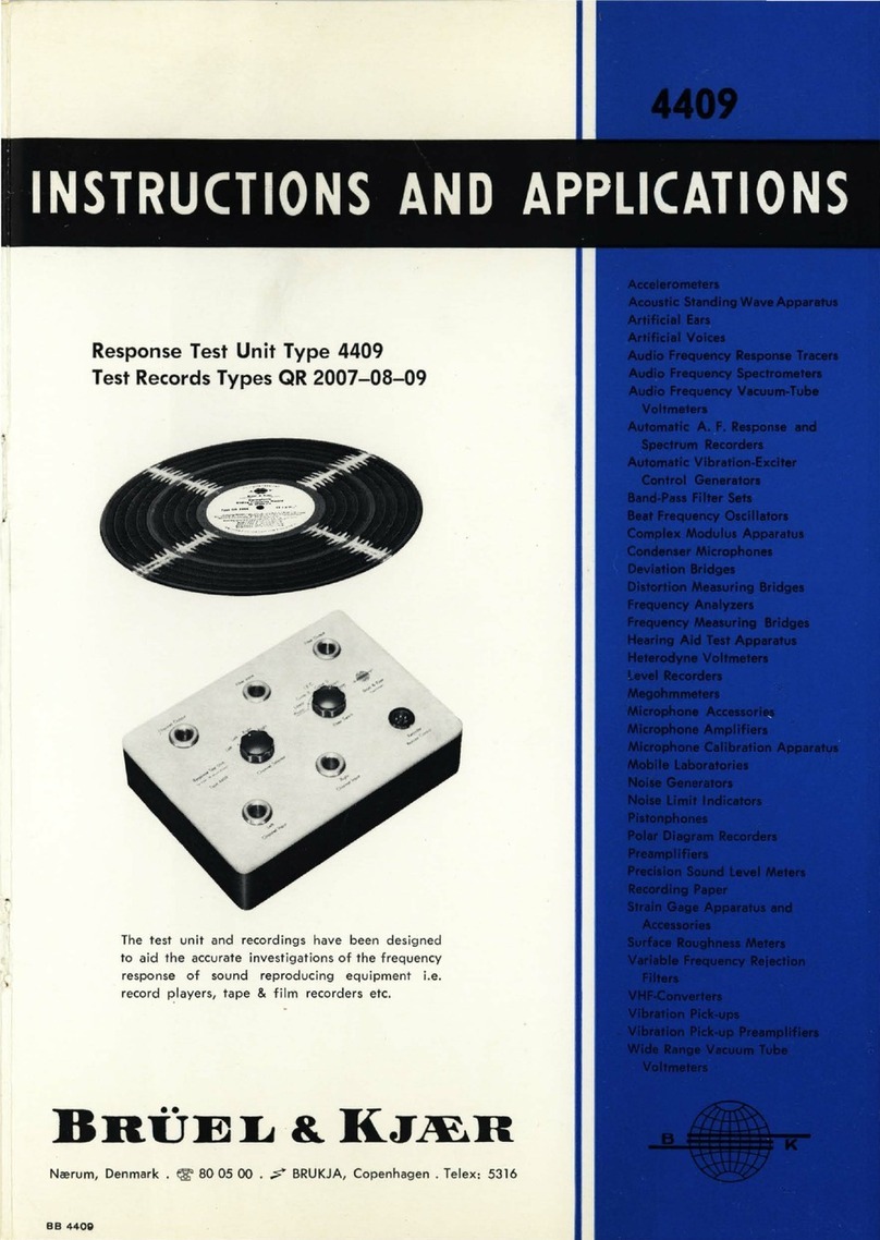
Response Test
Unit
Type 4409
Test Records Types
QR
2007-08-09
The
test
unit
and
recordings have
been
designed
to
aid
the
accurate investigations
of
the
frequency
response
of
sound
reproducing
equipment
i.e.
record players,
tape
& film recorders etc.
BHUEL
&
KJJEH
Ncerum, Denmark •
~
80
05
00 .
.;;;"
BRUKJA,
Copenhagen.
Telex: 5316
BB
4409


Response
Test
Unit
Type 4409
Test
Records
Types
OR
2007-08-09
Reprint
September
1965

Contents
1.
Description . . . . . . . . . . . . . . . . . . . . . . . . . . . . . . . . . . . . . . . . . . . . . . . . . . . . . . . 3
Purpose
of
the
Equipment
. . . . . . . . . . . . . . . . . . . . . . . . . . . . . . . . . . . . . . . . . . 3
Description
of
the
Test
Records
. . . . . . . . . . . . . . . . . . . . . . . . . . . . . . . . . . . . 4
General . . . . . . . . . . . . . . . . . . . . . . . . . . . . . . . . . . . . . . . . . . . . . . . . . . . . . . . . . . . 4
Recording Characteristics . . . . . . . . . . . . . . . . . . . . . . . . . . . . . . . . . . . . . . . . . . 9
Recorded
Level
Tolerances . . . . . . . . . . . . . . . . . . . . . . . . . . . . . . . . . . . . . . . .
11
Response
Test
Unit
Type
4409 . . . . . . . . . . . . . . . . . . . . . . . . . . . . . . . . . . . . . .
13
Channel Selector . . . . . . . . . . . . . . . . . . . . . . . . . . . . . . . . . . . . . . . . . . . . . . . . . . 14
Equalizing Filter
...................
.
..............................
14
Synchro-Starter
. . . . . . . . . . . . . . . . . . . . . . . . . . . . . . . . . . . . . . . . . . . . . . . . . . . 14
General Description
................................................
14
Functioning
.......................................................
16
2. Operation
..............
·. . . . . . . . . . . . . . . . . . . . . . . . . . . . . . . . . . . . . . . . . .
17
Practical
Hints
for
Use
of
the
Test-Records
..........................
17
Automatic
Frequency
Response
Plotting
. . . . . . . . . . . . . . . . . . . . . . . . . . . .
17
Automatic
Gliding
Frequency
Cross-Talk
Measurements
..............
19
General
...........................................................
19
Operating Procedure
..............................................
20
Synchronous
Filtering
Adjustment
. . . . . . . . . . . . . . . . . . . . . . . . . . . . . . . . . .
22
Automatic
Distortion
Measurements
. . . . . . . . . . . . . . . . . . . . . . . . . . . . . . . .
25
Examples
of
Practical Results . . . . . . . . . . . . . . . . . . . . . . . . . . . . . . . . . . . . . .
26
Use
of
the
Test
Record
QR 2008
....................................
28
Spot
Frequencies
..................................................
28
1
kHz
Reference
Tones
. . . . . . . . . . . . . . . . . . . . . . . . . . . . . . . . . . . . . . . . . . . . 28
100
Hz
Tracking
Test
..............................................
28
Tone
Arm
Resonance
..............................................
29
Test
of
Tape
Recorders
etc. . . . . . . . . . . . . . . . . . . . . . . . . . . . . . . . . . . . . . . . . 30
Synchro-Start
of
a
Continuous
Recording
. . . . . . . . . . . . . . . . . . . . . . . . . . . . 33
Specifications . . . . . . . . . . . . . . . . . . . . . . . . . . . . . . . . . . . . . . . . . . . . . . . . . . . . . . . . 34
1.
DESCRIPTION
1.
Description
Purpose
of
the
Equipment.
The
Response
Test
Unit
Type
4409 is
intended
for
use
with
the
B &K auto-
matic
frequency
response
plotting
equipment
when
investigating the frequency
response
of
sound
reproducing
equipment.
Fig.
1.1
shows
an
example
in
which
the
4409
and
a
test
record
are
involved in
the
testing
of
a
stereophonic
record
player.
Head
under
test
Mic.
Amplifier
Record
Player
Level
recorder
I
I
I
I
lAo.
0006
I
~~~~,L-----·-R~e~~t..:.~~~~J
962'165
Response Test Unit
Fig. 1.1. Measuring set-up for automatic plotting
of
the
frequency response
of
a stereophonic record player.
The
4409 fulfils
three
different
functions:
(a)
channel
selection
in
the
case
of
stereophonic
equipment
either
manually,
when
only
one
channel
is investigated,
or
automatically
at
a
recuring
fre-
quency
of
1.2
Hz
for
automatic
cross-talk
or
comparison
measurements.
(b) equalization,
by
different
RC
filters,
of
the
recording
characteristic
of
the
test
record.
(c)
synchronization
of
the
paper-drive
of
the
Level
Recorder
Type
2305
with
the
reference
recordings
(record
or
tape)
under
reproduction.
It
is
thus
possible
to
automatically
plot
the
frequency
response
of
the
sound
reproducing
equipment. A
typical
experimental
result
is
shown
in
Fig. 1.2.
8

1.
DESCRIPTION
Where
the
recorder
is
integrated
with
the
reproducer,
as
in
the
case
of
tape
recorders,
motion
picture
systems
etc.,
reference
recordings
are
taken
from
the
constant
voltage
output
of
a
generator,
but
in
the
case
of
phonograph
testing,
accurate
reference
disc
recordings
are
needed.
The
Gliding
Frequency
Recordings
Type
QR 2007
and
2009
are
especially
designed
for
the
purpose
of
frequency
response
investigation.
They
provide
-""""--
....
StlftophO!l!C
pick-up
typ•
• •
Ortafon
SPli-G
Nnl
Fjlter
I
jn
"
OR
2007
bondl
...
,..,__1___:_.
"'
- 5·7·
1962
.,.,oo
'-""'--
-101
L.LA.tY
;
__
_
,.
lOdB
~~
.
......,,...~
.
...
;_
,,tO
QP
1123
10
Fig. 1.2.
Typical
experimental
result obtained
by
means
of
the
set-up
of
Fig.
1.1.
(Test
of
a
high
quality
stereophonic
head
presenting a certain unbalance).
The
total
duration
of
one
plot
is 35 sec.
between
the
instant
when
the
pick-up
is
put
down
on
the
record QR 2007
and
the
instant
when
the
set-up
is
ready
to start a
new
plot.
continuous
frequency
sweeps
from
20 Hz
to
20
kHz,
with
lateral
modulation
on
the
QR 2007
and
left,
right,
lateral,
ve
rtical
modulations
on
the
QR 2009'.
The
Pickup
Test
Record
Type
QR 2008 is,
on
the
other
hand,
designed
for
measurements
at
fixed frequencies
and
for
tone
arm
resonance
investigations.
It
is
intended
for
pick-up
design
work,
and
also
for
general
purpose
checks
in
combination
with
the
gliding
frequency
records
when
curve
plotting
equipment
is
not
available.
Description
of
the
Test
Records.
General.
The
B & K
reference
recordings
are
delivered
in
boxes
containing
five
identical
vinylite
records
and
one
instruction
manual
(Fig. 1.3).
Both
sides
of
each
record
being
identical, a
total
of
ten
sides
are
available,
a
large
enough
quantity
to
guarantee
a
great
number
of
playings
without
4

1. DESCRIPTION
alteration
of
the
characteristics.
This
number,
however,
is
greatly
dependent
on
the
care
exercised
in
the
use
of
the
records.
By
conserving
one side
as
a
reference,
it
is
possible
to
check
on
the
service life
of
each
record
in
use.
Fig. 1.3. Gliding Frequency Recordings
Type
QR 2007.
The
cutting
process
and
the
dimension
are
in
accordance
with
the
Recom-
mendation
of
the
International
Electrotechnical
Commission
(IEC 98/98-1)
recognized
by
most
countries.
The
detailed
specifications
are
given
at
the
end
of
this
manual.
The
reproduction
of
the
label
of
the
QR 2007 (Fig. 1.4)
and
the
photograph
of
a
section
of
the
record
,
illuminated
by
a
grazing
light
beam
(Fig. 1.5),
show
the
exact
composition
of
the
recordings.
The
QR 2008
and
QR 2009
are
described
in
the
same
way
by
figures 1.6
through
1.9.
The
original
sinusoidal
signal
used
for
recording
the
disc
tracks
was
obtained
from
a B & K
Beat
Frequency
Oscillator
with
especially
low
distortion.
For
the
recording
of
the
gliding
frequency
bands
the
frequency
of
the
signal
was
varied
according
to
a
function
of
time
which
was
purely
logarithmic
within
.± 2.2 %
± 1.3 Hz.
This
tolerance
is
equal
to
the
tolerance
on
the
determination
of
the
recorded
frequency
when
using
the
Gliding
Frequency
Records
at
the
exact
specified
rotation
speed
(
45
rpm)
and
assuming
a
logarithmic
sweep.
5

1.
DESCRIPTION
Briiel &
Kjaer
Copenhagen Denmark
Monophonic
Gliding
Frequency
Record
20-20000
c/s
Type
OR
2007
0
45
r.p.m.
D
Frequency Sweeps: Logarithmic
20
c/s
to
20
kc/s
in
15
seconds
Start Marking
(20
c/s point):
Cease
of the 1 kc/s signal preceeding
each
band
Recording Characteristic:
IEC
Standard No. 3 without treble emphasis
(constant velocity above 1 kc/s) .
Recorded Velocity
at
1 kc/s: 3.
16
cm/s
r.m
.s.
Bands 1 to
10:
lateral cut
fig.
1.4.
Label
of
the
QR 2007.
2
4
10
QR
2007
Bands 1 to
10
: A B
20
cfs
20
kc
fs
8/9 octave per rev.
Fig. 1.5.
Section
of
the
QR
2007
showing
the
succession'
of
gliding frequency
bands
preceded
by
a 1
kHz
start
and
reference
signal.
6

Bruel &
Kjaer
Copenhagen
Denmark
Pick-up
Test
Record
33
1
/a
r.p.m.
6
Section
1
Vel~~;~:
r:r:~~o~si~~~.~
0
c
~-~~.~
i~
2
15;
~~dku~~tion.
Band 1:
45
° left modulation (A). Band 2
:45
° right modulation (B).
Section
2 0
Section
3
Reference Tones, 1 kc/s, 4 x
60
sec
. · Lateral Tracking
Test,
Velocity level: 2.
24
em/sec. rms
(45
°)
100
c/s
(A+B),
5 x
15
sec
.
(3.16 cm/s lateral or vertical) Band 1:
0.001
em
peak amplitude
Band
1:
45
° left
(A~
Band
2:
0.
002
• • »
==~~
~~
t!;e~~~h(~~)B)
==~~
=~
g
:
~
: :
Band 4: vertical
(A-B)
Band 5: 0.
005
» »
Section
4
Vertical Tracking Test,
as
section
3 but with vertical
(A-B)
modulation.
Section
5
Logarithmic Frequency
Sweeps
10
c/s -
100
c/s
in
16'/•
sec
.
Start
Marking
(10
c/s
point):
cessation
of
the
1 kc/s signal
Recorded
levef:r~~~~i~~t
~':::;li~~d~
·
0.00113
em
peak
.
==~~
~~
:~
~
~~~~~~~)
==~~:~~~~~~~~~(~A~~)
Section
6
as
section
1,
but with small groove
speed
'?ec0,., . "'ef\\
163696
ded
on
ORTOFON
Eo.\l'll
Fig. 1.6.
Label
of
the
QR
2008.
Spot frequencies
}A
20-16-12.5-10
kc/s 8
(0.6
em/sec rms)
1kc/s reference
}~
tone
(3
.
16
cm/secl
A-8
Tracking
test
I
(compliance)
.
A+8
100
cts bands of
increasing ampl.
A-,8
0.
001
to
0.005
em
10-100
C/S
sweeps}A
constantamplitud 8
(0
.
00113
em
peak)
A+8
for
tone
arm
A-8
resonance
as
first
section
}~
QR
2008
2
3
5
6
(33113
rpm)
+t.'3462
1. DESCRIPTION
Fig. 1.7.
Section
of
the
QR
2008
showing
the
succession
of
bands.
7

1.
DESCRIPTION
Brtiel & Kjcer
Copenhagen Denmark
Stereophonic
Gliding
Frequency
Recor~
20-20000
c/s
Type
OR
2009
0
45
r.p.m.
,6_
Frequency Swaaps: Logarithmic
20
c/s to
20
kc/s
in
50
seconds
Start Marking
(20
c/s point) :
Cease
of the 1 kc/s signal preceeding each band
Recording Characteristic:
IEC
Standard
No.3
without treble emphasis
(constant velocity above 1 kc/s) . ·
Recorded Velocity
at
1 kc/s:
2.24
cm/s r.m.s.
in
45
° modulation
(3.16 cm/s
in
lateral and vertical modulations)
Bands 1 and 5:
45
° left modulation
(A)
Bands 2 and
8:
45
° right modulation
(B)
Bands 3 and
7:
lateral modulation (A+B)
Bands 4 and
8:
vertical modulation (A-B)
Fig. 1.8.
Label
of
the
QR
2009.
B
~
AtB
~
A
8
A+B
A- B
Pig. 1.9.
Section
of
the
QR 2009
showing
the
succession
of
gliding frequency
bands
preceded
by
a 1
kHz
start
and
reference signal.
8

1. DESCRIPTION
Recording Characteristics.
Pick-ups
should
be
tested
with
reference
to
the
internationally
recognized
characteristics
if
they
are
intended
to
give
constant
output
as
a
function
of
frequency.
Gliding
frequency
records
should
in
general
be
cut
according
to
the
recording
characteristics
shown
in
Fig. 1.10-bottom.
In
the
case
of
the
B & K Gliding
Frequency
Records,
a
characteristic
as
shown
on
top
of
Fig. 1.10,
which
is
converted
by
an
equalizing
filter
in
the
measuring
chain
to
the
appropriate
characteristics
has
been
adopted.
The
reason
for
the
high
fre-
quency
level
limitation
on
the
record
is
that
if
true
reproduction
is
intended,
the
radius
of
curvature
of
the
modulated
groove
wall
must
remain
appreciably
larger
than
the
stylus
tip
radius.
The
wave-length
being
determined
by
the
chosen
groove
speed,
and
the
stylus
tip
radius
being
normalized
to
15-18
f.1,
for
stereophonic
pick-ups,
this
sets a
db
:::
0
·g
~
i-10
~
-20
20
+20
db
+10
IIII
I I I I II
Hitlf11
11
1
/ Recording Characteristic
v Gliding Frequency
Reco
1
rds
Cl.R
2007
&
Cl.R
2009
__
....
IIIII
I I I II
II
II
50
100
200
500
1000 2
000
10000 20000
--
Type
4409
Equilizing
Filters
Characteristics
[/
llN
Filter
Switch
pos.
: I.E.C. Curve 2,
• • " :I.E.C. Curve 3 /
II
I
r>-
>"
Fi~te~
s
1
w~t~~
p~s.:
Lin.
...,_.;:-:::::;.::::
_,
I
Il
l I
20
50
100
200 500 1
000
2000 10000 20000
b
+20
+10
~
> 0
...,
...,
~-1
0
-20
r--
20
IIIII
Total Characteristics I
-
(Types
tl.R
2007109+4409)
111111
I I I
Filter
Switch
pos
.:
L~n
.
.\
v
/
1-"
50
100
200
)/
,/
/
;
:::.;:;--·
I
f"'
I
Fi
lter
Switch
pos
.:
I.E.C.
Curve~j_
t--
•
..
• : I.E.
C.
Curve3
IIIII
I I I I I
IIIII
II
II
II
II
500
1000 2000
II
Ill
II
Il
l
10000 20000
~6232
tl
Fig. 1.10. Recording characteristics available
when
using
the
Gliding Frequency
Recordings in connection
with
the
Response Test Unit
Type
4409.
The
curve
no. 3 is specified
by
the
International Electrotechnical Commission in its
publication no. 98-1 for stereophonic recordings.
9

1.
DESCRIPTION
maximum
limit
to
the
amplitude
of
modulation
at
high
frequencies.
The
conditions
obtained
on
the
B & K Gliding
Frequency
Records,
where
the
recorded
velocity is
limited
at
20
kHz
to
3.5
cm/s
peak
in
each
channel,
are
illustrated
in
Fig. 1.11.
Band 1
Band 8
't62J62
Fig. 1.11. Views in
the
plane
of
modulation
showing
the
relative
dimensions
of
the
maximum
allowed
tip
radius
and
the
minimum
radius
of
curvature
e
on
the
record QR 2009's
outer
and
inner
bands presenting a
diameter
of
28.2
and
12.6
em
respectively
at
20
kHz.
Note
that
e is
proportional
to
the
square
of
the
diameter
D
(or
of
the
groove speed).
The
speed
of
rotation being
45
r.p.m., i.e. o.75 r.p.s.,
the
expression for e is
_
1r
(o.75 D)2 _ 88
___!!!__
e-
2
tv
-
o.
f v
where
f is
the
frequency
and
v
the
peak
channel
velocity
(3.5
cm/s).
The
advantage
of
the
standardized
recording
characteristic
is
to
give
the
optimum
signal-to-noise
ratio
by
increasing
the
recorded
amplitude
at
low
fre-
quencies,
where
the
rumbles
and
vibrations
of
the
turntable
are
important,
and
the
recorded
velocity
at
high
frequencies
where
the
surface
noise
increases
rapidly.
Using
any
other
characteristic
will
result
in
a
decrease
of
the
overall
signal-to-noise
ratio
after
correction
of
the
characteristic
by
an
equalizing
filter.
In
the
case
of
the
B & K Gliding
Frequency
Records
the
signal-to-noise
ratio
is
decreased
by
about
6 dB
after
equalization,
but
this
does
not
affect
the
measuring
possibilities.
In
addition,
the
correction
of
the
recording
characteristics
can
easily
be
made
by
means
of
a
simple
RC filter. Using
different
filters
enables
the
selection
of
different
characteristics.
This
is
of
interest
since
there
are
differences
between
the
various
national
standards.
Using a
suitable
filter, a
constant
recorded
velocity
reference
can
also
be
obtained
for
testing
electrodynamic
pick-ups
without
their
associate
equalizers.
Three
different
characteristics
are
thus
10

1. DESCRIPTION
provided
by
the
B & K
measuring
equipment.
See Fig. 1.10.
The
determination
of
the
correcting
filters
results
immediately
from
the
mathematical
definition
of
the
standard
characteristics:
where
w is
the
angular
frequency
and
h = 50
p,s
(curve
2)
or
75
ftS
(curve
3),
12
= 318 p,s,
t3
= 3180
,flS.
The
recording
characteristics
of
the
B & K
test
records
corresponds
to
h = 0,
t2
= 318
flS,
t3
= 3180
,p,s.
As
seen
on
the
figures,
each
gliding
frequency
band
is
preceded
by
a 1
kHz
start
and
reference
signal
lasting
a
few
seconds.
The
starting
point
of
the
logarithmic
sweep
coincides
with
the
end
of
the
1
kHz
modulation.
The
purpose
of
this
1
kHz
signal
is,
in
addition
to
the
determination
of
the
fre-
quencies
in
the
results
as
described
below
(synchronization
of
test
signal
and
recording
paper)
to
allow
a
quick
adjustment
of
the
measuring
chain
sen-
sitivity
to
be
made
before
actual
measurements
are
taken.
On
all
records
the
1
kHz
start
signal
is
modulated
laterally
(A+
B)
or
vertically
(A
-
B)
when
preceding
a
vertical
(A
-
B)
band.
Recorded
Level
Tolerances.
The
accuracy
in
amplitude
of
the
reference
recordings
is
determined
to
within
o.5 dB
in
a
limited
frequency
range
by
the
optical
method
of
the
"Filtered
B-line
light
pattern
"
referred
to
in
the
American
Standards.
Over
the
whole
frequency
range,
the
accuracy
is
checked
by
means
of
a
professional
electro-
dynamic
pick-up
especially
selected
for
this
purpose.
The
check
is
carried
out
at
two
different
rotation
speeds
in
order
to
distinguish
the
non-linearities
of
the
pick-up
from
those
of
the
record
itself:
a
change
in
rotation
speed
accompanied
by
a
corresponding
change
of
the
time
constant
of
the
equalizing
filter,
produces
a
frequency
translation
of
the
record
defects,
while
the
fre-
quency
response
of
the
pick
-
up
is
unchanged.
The
investigation
is
carried
out
both
on
the
nickel
"master"
and
on
the
vinylite
records.
The
flatness
in
frequency
characteristic
obtained
in
serial
production
is
better
than
:± o.5 dB
from
100
Hz
to
10
kHz
and
± 1 dB
from
20
Hz
to 16 kHz.
Between
16
k~z
and
20
kHz
a
dip
in
the
frequency
response
which
is
due
to
a
spurious
resonance
in
the
disc
recorder
might
be
present
and
the
tolerances
are
therefore
enlarged
as
shown
on
Fig. 1.12.
Another
important
characteristic
of
the
stereophonic
test
records
is
the
upper
limit
of
the
recorded
cross-talk
on
the
unmodulated
groove
walls
of
bands
A
and
B.
This
corresponds
to
the
separation
of
the
disc
recorder
since
it
is
practically
unaffected
by
disc
copying
operations.
The
determination
of
the
spurious
cross-talk
in
the
pick-up
employed
for
checking
the
recorded
cross-
11

1.
DESCRIPTION
talk
can
also
be
made
by
comparison
between
two
tests
of
different
rotation
speeds, giving a
frequency
translation
of
the
characteristic
for
the
record
only.
The
recorded
cross-talk,
expressed
in
dB
with
reference
to
the
modulation
level, is
the
separation
between
channels
of
the
recording.
The
minimum
separation
of
the
QR 2009 is
shown
on
Fig. 1.13.
The
tolerances
of
the
Test
Recordings
Type
QR 2008
are
given
on
p. 5.
db
+1
0
-1
QR
2009
QR
2007
QR
2009
~
QR
2007
~
_4
logarithmic
sweep accuracy:
~±2
.
S%±1c/s
~
...
....
100
1000
CIS
Fig. 1.12. Curves
silowing
tile
manufacturing
tolerances
wllich
include
both
the
record itself and
the
equalizing filter characteristics.
The
accuracy
is best
for lateral
modulation
and
the
tolerances are
therefore
narrower
for
the
db
-10
-20
-30
-40.,
20
Record
QR
2007.
..
"'
...
100
8 =unmodulated wall
(upper
limit
of
the
records crosstalk,
measured
in
1/3 octave
filters)
-'00
kiOO
a:JDO
sooo
10000
1000
C/S
10000
20000
~fi2333
Fig. 1.13.
Limit
of
cross-talk
on
the
stereophonic recordings
of
Type
QR 2009,
bands
1-2
and
5-6,
measured
in
dB
with
respect
to
the
recording level
(i.e.:
maximum
measurable
channel
separation).
N.B. Valid
only
when
the
playing
angle does
not
deviate
much
from
the
cutting
angle (10° ±
5°).
12

1. DESCRIPTION
Response Test
Unit
Type
4409.
The
Unit
Type
4409
groups,
in
the
same
cabinet,
three
independent
sections
which
are
connected
as
shown
in
Fig. 1.15.
The
left
hand
knob
(Fig. 1.14)
relates
to
the
channel
selector
and
the
right
hand
one
to
the
filter
section.
The
synchro-starter
is
fully
automatic.
The
unit
is
transistorized
and
the
power
supply
is
taken
from
the
24 Volt
DC
circuit
of
the
Level
Recorder
Type
2'305
via
the
multi-pin
plug.
Fig. 1.14. Response
Test
Unit
Type
4409.
4409
462335
Fig. 1.15.
Block
diagram
of
the
4409.
(The
synchro-starter
is
only
connected
to
the
filter-input
terminal
when
a
DC
power
supply
of
24 V is applied between
pins
1
and
4
of
the
multipin
plug).
13

1.
DESCRIPTION
Channel-selector.
The
two-channel-selector
consists
of
a
low
noise
relay
driven
by
the
output
of
a
bi-stable
multivibrator.
The
multivibrator
may
be
blocked
in
one
of
the
other
positions
by
setting
the
CHANNEL
SELECTOR
switch
in
"left"
or
"right"
positions.
In
the
"left-right"
position,
an
automatic
switching
is
obtained
at
a
recurring
frequency
of
1.2 Hz.
In
other
words,
each
channel
is
connected
during
a
period
of
o.4
seconds
.
Transients
and
switching
times
are
shorter
than
o.02 seconds.
Equalizing Filter Section.
Fig. 1.10
shows
the
three
different
equalization
characteristics
provided
by
this
section.
They
are
selected
by
means
of
the
FILTER
SWITCH
which
also
has
a
fourth
position
marked
"Direct"
where
the
filter
section
is
short-circuited
us
needed
when
testing
sound
reproducers
other
than
record
players
(e.g.
tape
recorders)
.
The
filters
are
of
the
RC
type
and
are
designed
to
be
used
as
external
filters
on
the
B & K
amplifiers
such
as
the
Microphone
Amplifier
Type
2603.
The
standard
characteristics
are
obtained
only
if
the
test
records
are
rotated
at
the
specified speed.
Synchro-starter
Section.
General Description.
The
purpose
of
this
section
is
to
command
the
paper
drive
start
of
the
Level
Recorder
Type
2305
at
the
end
of
the
1
kHz
start
signals
recorded
on
the
test
records,
thus
automatically
ensuring
synchronism
between
the
instantaneous
test
frequency
on
the
record
and
the
frequency
calibration
of
the
recording
paper.
QR
2009
Tested
pick-up
Gear
Level Recorder
Paper
drive
1-i_._+WW\Hiiii---1~
(!)
.._____.,
~til
Automatic
113
octave
filter
switch
Fig. 1.16.
Block
diagram
of
the
equipment
for
automatic
frequency
response
and
separation
measurements.
14

1. DESCRIPTION
An
important
point
for
the
practical
feasibility
of
this
synchronization
is
that
the
time
delay
of
the
paper
drive
start
should
be
negligible.
The
clutch
of
the
Level
Recorder
Type
230<5,
as
schematically
outlined
in
Fig.
1.16, is
engaged
when
no
current
passes
through
it
and
disengaged
when
excited.
It
is a
non-
slip device
and,
since
the
coupling
of
the
paper
drive
system
to
the
continu-
ously
rotating
synchronous
motor
introduces
a negligible
variation
of
kinetic
energy
in
the
system,
the
start
of
the
paper
drive
occurs
practically
instantane-
ously
when
the
current
is
cut.
The
command
is
thus
made
from
the
signal
recorded
on
the
test
disc,
by
simply
actuating
a
relay
device
cutting
the
clutch
circuit
at
the
end
of
the
start
signal.
This
is
performed
by
the
synchro-
starter
whose
block
diagram
is
sketched
in
Fig. 1.17.
Type
2305
Type
4409
Filter
input
Fig. 1.17.
Block
diagram
of
the
automatic
start/stop
arrangement
(Synchro-
starter
of
4409 +
clutch
circuit
of
the
2305).
The
scanning
speeds
of
both
the
disc
turn-table
and
the
Level
Recorder
paper
drive
are
tied
by
the
mains
frequency
and
no
mechanical
connection
is
needed.
This
allows
the
turn-table
to
be
installed
freely
on
an
antivibration
support
which
is
an
important
point
for
precise
measurement.
The
starting
signal
is
applied
to
the
"Filter
Input"
terminal
of
the
4409,
and
should
have
the
following
characteristics
for
operating
the
starter:
Frequency:
Voltage:
Duration:
1ooo
Hz .± 100 Hz.
from
o.1
to
32 V r.m.s.
(at
1
kHz).
at
least
o.1
second.
Note:
By
means
of
a
relay
connected
in
parallel
with
the
clutch
of
the
Level
Recorder,
the
syncho-starter
is
only
connected
to
"Filter
Input"
when
the
connection
to
the
recorder
is
made
and
when
the
paper
drive
is
stopped.
15

1.
DESCRIPTION
Detailed
Functioning
of
the
Relay
Arrangement.
The
synchronous
motor
of
the
2305 is
running
continuously
and,
as
can
be
seen
from
Fig. 1.16
the
start
of
the
paper-drive
is
obtained
by
disconnecting
the
24 V
supply
across
the
clutch
coil. Since
the
relay
01
is
connected
in
parallel
with
the
clutch
coil,
the
synchro
-
starter
is
only
connected
to
"Filter
Input"
when
the
paper
drive
is
stopped.
The
relay
circuits
for
01,
02
and
03
are
all
sketched
in
Fig.
1.17.
The
relays
are
shown
in
their
released
position.
Before
connecting
the
4409
the
Level
Recorder
should
be
started
by
setting
the
controls
as
shown
on
Fig. 2.1
and
2.2.
When
connecting
the
4409 to
the
2305,
the
relay
03
then
short-circuits
the
single
chart
push
button
which
otherwise
should
have
been
lifted
up
to
obtain
the
automatic
stop.
The
paper-drive
stops
as
soon
as
the
automatic
stop
switch
is closed
by
the
cam
and
the
24 V
supply
is
applied
to
the
clutch.
When
the
looo
Hz
start
signal
arrives
through
the
Filter
Input
,
the
relay
02
is
energized
which
in
turn
causes
03
to
be
energized
whilst
"Single
chart"
is still
short
circuited,
but
now
by
02.
When
the
1ooo
Hz
start
signal
ceases,
02
is
released,
but
03
is
still
energized
since
its
coil
has
a
much
larger
resistance
than
the
clutch
coil
which
is fed
in series
with
it
from
the
24 V
supply.
The
short-circuit
across
"Single
chart"
is
therefore
interupted
and
the
clutch
is released,
starting
the
paper
drive.
03
is
finally
released
by
the
cam
releasing
the
automatic
stop
switch.
16

Operation
Practical
Hints
for
Use
of
the
Test
Records.
General Instructions.
2.
OPERATION
The
test
records
should
be
handled
with
the
same
care
as
commercial
high
fidelity
LP
records.
The
number
of
playings
which
can
be
made
without
alteration
of
the
characteristics
is
greatly
dependent
on
the
care
exercised
in
the
use
of
the
records.
By
conserving
one
record
si~e
as
a
reference,
it
will
be
possible
to
check
on
the
service
life
of
each
record
in
use.
It
is
of
course
of
prime
importance
to
check
the
reproducing
stylus
tip
and
the
tracking
weight
before
each
record
playing.
The
tip
radius
should
be
between
12
and
18
p,
(o.0005
and
o.0007
inch.)
or
26
fl
(o.OOl
inch.)
in
the
case
of
lateral
bands,
with
an
included
angle
of
40°
to
50°.
The
records
are
cut
in
accordance
with
the
Recommendations
of
the
IEC
which
are
recognized
by
most
countries.
All
modulations
are
sinusoidal
with
negligible
distortion.
Finally,
the
records
should
be
carefully
protected
from
dust.
The
use
of
"antistatic"
cleaners
is
recommended.
Turn-table.
When
reproducing
heads
are
to
be
tested
separately,
a
good
professional
turn-
table
should
be
selected,
especially
with
regards
to
investigations
at
low
frequencies,
where
the
influence
of
wow
and
rumble
is
predominant.
The
rotating
speed
must
be
adjusted
with
great
care
by
stroboscopic
comparison
with
the
mains
frequency.
Finally,
it
is
recommended
to
isolate
the
turn-table
and
possibly
also
the
preamplifier
from
external
vibrations.
This
may
be
done
very
efficiently
by
suspending
the
table
supporting
the
two
devices
from
the
ceiling
by
means
of
four
rubber
tubes.
{Another
possibility
is
the
use
of
electrical
high-pass
filters).
Use
of
rotating
speeds
other
than
nominals.
Since
the
test
frequency
and
velocity levels
are
proportional
to
the
rotating
speed,
it
is
possible
to
extend
the
frequency
range
of
the
tests
by
using
different
rotating
speeds.
However,
it
is
then
necessary
to
modify
the
RC
equalizing
filters
employed
accordingly,
by
means
of
a
proportional
change
of
the
capacitors.
Automatic
Frequency
Response
Plotting.
In
the
following,
an
example
of
operating
procedure for
automatic
frequency
response
plotting
by
means
of
the
B & K
Instruments
Type
2603, 4409
and
2305
is
given.
17

2.
OPERATION
It
is
essential,
however,
that
the
instruction
manual
of
each
instrument
be
read
carefully
before
using
the
equipment.
1)
Place
the
record
player
on
a
vibration
free
table.
Connect
and
set
the
apparatus
as
shown
in
Fig.
2.1.
Select
the
desired
recording
characteristic*)
Pick-up
under
test
Cont.
ecord.
0 0
fig. 2.1.
Set-up
for
automatic
frequency
response
plotting
with
a QR 2001
record.
When
using a QR 2006 or 2009
the
adjustments
are
the
same
with
~xception
of
the
settings
of
the
Level
Recorder,
which
then
should
be a
...
fhown
on
Fig. 2.2. A single lead is
recommended
between
Amplifier
ana
Recorder since
the
ground
connection
is
already
made
by
the
synchro-starte1
connection.
by
means
of
the
4409's
FILTER
SWITCH.
The
paper
drive
controls
of
the
2305
are
set
to
"on",
"start",
"forward".
2)
Preliminary
Adjustments.
It
is
convenient,
in
order
to
ensure
that
the
correct
automatic
stop
position
is
attained,
to
play
a
record
band
before
actual
measurements
are
taken.
In
addition
it
will
be
possible,
during
this
preparatory
playing,
to
adjust
the
sensitivity
of
the
measuring
instruments.
Proceed
as
follows:
a)
Place
the
pick-up
on
a
lead-in
groove
for
playing
the
selected
band.
b)
If
the
automatic
synchro-starter
does
not
operate
after
a
few
seconds
playing,
check
that
the
speed
of
rotation
is 45
r.p.m.
and
switch
METER
RANGE
on
the
2603
to
10 m
V.
Also
check
that
the
pick-up
under
test
is
in
normal
condition.
*)The
recording
characteristic
should
be selected
in
order
to
obtain
a
constant
reference
level..
With
amplitude
sensitive pick-ups
such
as
piezoelectric devices
or
other
types
with
built
in
equalizers,
the
positions
"IEC
Curve
2
or
Curve
3"
should
be used.
(The
IEC specifies
Curve
3
for
stereophonic
recordings).
With
velocity sensitive pick-ups
such
as
electrodynamic
devices,
the
position
"Lin."
which
gives
constant
recorded
velocity
conditions
should
be
used.
18
Other manuals for 4409
1
This manual suits for next models
3
Table of contents
Other BRUEL & KJAER Test Equipment manuals

BRUEL & KJAER
BRUEL & KJAER System V User manual

BRUEL & KJAER
BRUEL & KJAER HF HATS 5128 User manual

BRUEL & KJAER
BRUEL & KJAER 4914 User manual

BRUEL & KJAER
BRUEL & KJAER 4292 User guide

BRUEL & KJAER
BRUEL & KJAER 4912 User manual

BRUEL & KJAER
BRUEL & KJAER 4297 User manual

BRUEL & KJAER
BRUEL & KJAER 3923 User manual

BRUEL & KJAER
BRUEL & KJAER 5998 User manual

BRUEL & KJAER
BRUEL & KJAER 4226 User manual

BRUEL & KJAER
BRUEL & KJAER 4230 User guide