manuals.online logo
Brands
  1. Home
  2. •
  3. Brands
  4. •
  5. Vallox
  6. •
  7. Ventilation Hood
  8. •
  9. Vallox Slim Series Manual

Vallox Slim Series Manual

USE OF VENTILATION
OPERATING AND MAINTENANCE INSTRUCTIONS
In buildings with dwelling-specific ventilation the
resident can have an impact on the power of
ventilation. Adjustment takes place according to use
situation at the ventilation power controller, which is
situated either in the cooker hood or in a separate
control centre.
Normal operation (position 2 or 3)
Ventilation has to be continuous: the air volume of the
dwelling has to be changed at least every two hours.
"Away" operation (position 1)
When the dwelling is empty, ventilation can be lowered
from the normal operation position unless it puts the
structures or the ventilation system in danger.
Boost operation (positions 3 and 4)
Cooking, taking a sauna bath, washing, drying of
clothes, use of toilet, having guests, overheat or a
similar situation may cause a need for more powerful
ventilation than normally. This can be implemented by
boosting ventilation on the whole or for specific rooms.
As an example, the damper of the cooker hood is kept
open during cooking, but at other times it is shut or in
the minimum position.
Cooker hood operating controls
The cooker hood operates in the dwelling as a
local extraction valve of the cooker and the
general extraction valve in the kitchen and as the
adjustment device for the ventilation system.
NOTE!
In order to produce a sufficient
exchange of air, follow the venti-
lation plan that defines the posi-
tion of the controller in a normal
living situation.
Cooker hood damper controller.
Rotary-actuated, self closing
damper, equipped with a timer.
Turned to the right, the damper opens,
when the timer switches on and will
close the damper automatically within
60 minutes.
Damper in the open position
• Boosts the capacity to capture
cooking odours.
• Cooking on a cooker or in the oven.
• Unusual load situation in the kitchen
(such as using heavy detergents or
a large number of guests).
Rotary-actuated ventilation
controller
Cooker hood light switch
Turned to the left with the
damper in the off position:
• Normal living situation, boosts
extraction in the other rooms.
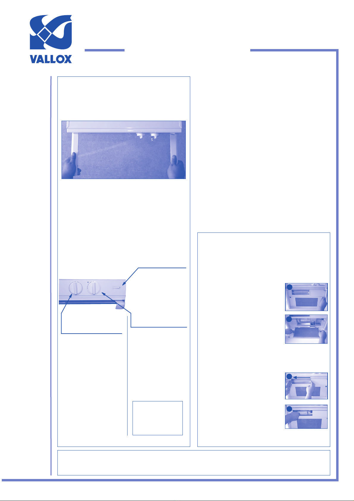
USE OF COOKER HOOD
• SLIM-LINE cooker hood is equipped with a
withdrawable glass. It is recommended to hold
the edging strips of the glass when pulling the
glass out and pushing it in.
• In boosted operation situations, such as during
cooking, it is recommended to pull the glass out
to the maximum position. This increases the
capacity of the hood to capture cooking odours.
• In other situations, such as during basic ventilation,
the glass can be pushed in to the minimum
position.
Closing ventilation in the dwelling also prevents the supply of pure outdoor air into the dwelling as well as the taking out of dirty air. Impurities coming from
people, structures and the earth, such as carbon dioxide, humidity, smells, formaldehyde, dust and radon, quickly spoil room air and cause health damage.
Excessive humidity may destroy structures and cause mould and fungal growth. Because of this the building regulations require that ventilation is in operation all
the time and that its power is adjusted as needed by the user.
WARNING
Changing lamps
Removing and cleaning grease filter
• Pull the glass of the cooker hood out to the
max. position.
• Turn the quick fasteners on the bottom plate
of the hood open (1).
• Turn the bottom plate to the lower position.
• Remove the grease filter from its holder (2).
• Wash the filter at least 1 to 2 times a month
with warm water and detergent, manually or
in a dishwasher.
• When the cooker is used a lot, wash the filter
sufficiently often.
• Pull the glass of the cooker hood out to the
max. position.
• Remove the protective glass of the lamp by
moving it to the left (3).
• Remove the lamp by pulling it to the left (4).
• Lamp type fluorescent lamp PL (11 W).
NOTE! Neglecting the instructions given for cleaning the grease
filter may cause a fire risk.
Also take care of the external tidiness of the
cooker hood. Detergents meant for the cleaning
of stove enamelled and plastic surfaces are
suitable for the cleaning.
In order to ensure a sufficient extract air volume,
take care of the cleanliness of the grease filter.
Clean the grease filter often enough by
removing it and washing it carefully.
COOKER HOOD MAINTENANCE
© VALLOX • We reserve the right to make changes without prior notice www.vallox.com
Vallox Slim Line
PTXPA
Cooker hood
MC
• 1.09.610ENG
• 14.9.2015
© VALLOX
1. Away position
2. Normal position
3. Boost position
4. Peak boost position
Rocker switch pressed
• Right edge down, light on.
• Left edge down, light off.
NOTE! It is
forbidden to burn
with a flame under
the cooker hood!
1
2
3
4
Distance from the lower surface of
the grease filter to an electric
cooker at least 500 mm and at
least 650 mm to a gas cooker.
Vallox Slim-Line
PTXPA MC COOKER HOOD
The cooker hood is fastened with the fastening supplies in the package.
1. Fasten the fastening brackets on the back edge and sides of the cooker hood to the
hood (Figure 1).
2. Lift the cooker hood in place and fasten the fastening brackets on the back edge to
the wall (Figure 2). The fastening screws in the accessory bag are suitable for
wooden, chipboard, concrete and masonry walls. When fastening on other surfaces,
use appropriate fixing accessories.
3. Fasten the fastening bracket on the side to the cupboard (Figure 3).
4. Connect the hood to the extract air ductwork of the ventilation system by using
a ø 125 mm spiral duct. Ensure that the connection is tight.
Make sure that the ductwork is fire resistant (Finnish Building Regulations E7).
The cooker hood must not be connected to a flue which is used for extracting
combustion gases from appliances running on other sources of energy than
electricity.
The regulations by authorities covering how extract air must be conducted have
to be taken into account.
A sufficient supply of fresh air into a room has to be arranged if the cooker hood
and a fire place, for instance, are used simultaneously.
NOTE!
Fastening
1
2
3
MOUNTING INSTRUCTIONS
© VALLOX • We reserve the right to make changes without prior notice 2
min. 500 mm
or
min. 650 mm
Electrical connection
Electrical connections must only be performed by an authorised person.
LED
COOKER HOOD
10 A
Vallox SC or MC ventilation unit
Note! There is no led connector
in SC units
DISTRIBUTION
PANEL
3 x 1.5 S
S
+
L
L
N
-
4 x 0.5 S
10V DC
Vallox Slim-Line
PTXPA MC COOKER HOOD
Measuring and adjusting PTXPA MC performance Basic air flow measurement
Boost air flow measurement
234567810 2030405070
10
20
30
40
50
60
80
100
200
300
400
Static pressure loss Pa
Air volume flow rate, dm3/s
20 holes open
60 80
30 holes open
60 holes open
40
holes open
50 holes open
70 holes open
80 holes open
DAMPER OPEN
DAMPER OFF
25 dB (A)
30 dB (A)
35 dB (A)
40 dB (A)
40 dB (A)
35 dB (A)
30 dB (A)
25 dB (A)
Basic ventilation
• When the damper is in the off position, the volume flow rate of the air in the cooker
hood can be measured and adjusted if needed on the basis of the static pressure loss
of the cooker hood and the adjoining performance curves.
• Measure static pressure loss of the cooker hood in the damper hole using the
measuring tube in the accessory bag (see the figure).
• Using the measured pressure and the number of open holes in the damper, you can
read the air volume flow in the adjoining curves.
Adjustment:
• Use the magnetic tape supplied with the cooker hood to conceal the needed number
of holes in the damper.
Boost ventilation
• When the damper is in the open position, the volume flow rate of the air in the cooker
hood can be measured on the basis of the static pressure loss of the cooker hood and
the adjoining performance curves.
• Measure static pressure loss in the cooker hood. The measuring point has to be by 2
x duct diameter size above the outlet collar of the cooker hood (see the figure).
• You can read the air volume flow using the measured pressure and the adjoining
curves.
MOUNTING INSTRUCTIONS
© VALLOX • We reserve the right to make changes without prior notice
3
Measuring point,
min. 2 x duct diameter
1.09.610ENG/14.9.2015
Vallox Oy • Myllykyläntie 9-11 • FI-32200 Loimaa • Tel. +358 10 7732 200 • www.vallox.com
© VALLOX • We reserve the right to make changes without prior notice
Vallox Slim-Line
PTXPA MC COOKER HOOD
MC CONTROLLER
Put the speed knob to position 1 and detach
the knob with a screwdriver or similar.
There are adjustment and measurement
holes below the knob.
Measure voltage at the - and S contacts,
adjust speed 1 for instance
at potentiometer 1.
Put the knob back in place, turn the knob
to the following speed position and detach
the knob again.
You can also carry out the measurement at
the terminal block, in locations shown in the
electrical diagram.
Indicator light
The indicator light (A) shown in Figure 1 is lit when the MC ventilation unit
controlled by the hood is operating. If the indicator light blinks at one-second
intervals, the ventilation unit reminds you of the need for maintenance. The reminder
is shown every six months. The maintenance reminder is reset when the cover of
the ventilation unit is opened. Explanations for other cases where the indicator light
blinks in fault situations are given in the instructions of the ventilation unit.
The indicator light is not in use if the cooker hood is used to control roof fans or
other ventilation unit or if the indicator light is not connected to the ventilation unit.
Adjustment of fan speeds
A low signal voltage comes to the controller, which means that the adjustment can
be made when the controller is connected and the ventilation unit is in operation.
• The adjustment is conducted in the four holes below the controller knob
(Figure 2) one speed at a time, at the potentiometer corresponding to each
speed.
• The voltage adjusted can be measured at the measuring points found below
the knob (markings S and -) or on the terminal block below a black protective
casing (markings S and –, see Figure 6) with a multimeter direct-current
voltage measurement. The adjustment range is ~2...11.2 V.
• Control voltage (air flow) rises when the potentiometer is turned clockwise.
Preset voltages are as follows: 2.5 V, 5 V, 7.5 V and 10 V.
Note! Do not set control voltage so low that the fan does not start (circa 1.5 V).
Sample adjustment of air flows:
Basic ventilation is adjusted at speed 2.
• Set the controller at speed 2 and measure air flows at the valves.
• If the total air flow is too low, set the control voltage higher
at potentiometer 2.
• If the total air flow is too high, set the control voltage lower
at potentiometer 2. Do not throttle the air flow unnecessarily with valves!
• The balance between supply and extract air flows in the Vallox MC ventilation
unit can be adjusted with the potentiometer inside the unit. Do not change
this balance during measurements carried out at other speeds.
• Adjust the away air flows correspondingly at speed 1 (potentiometer 1).
• Adjust the boost air flows correspondingly at speed 3 (potentiometer 3).
• You can usually leave speed 4 at full power.
Finally measure voltage at all speeds at the measurement pins and enter them in
the measurement record. In a terraced house, for instance, you can use voltage
measurement to copy the measurement in the first dwelling to other similar
dwellings.
1
2
3
4
6
5
A
Measure voltage at the - and S contacts, adjust
speed 2 at potentiometer 2, and so on.

This manual suits for next models

1

Other Vallox Ventilation Hood manuals

Vallox Slim Series Manual

Vallox

Vallox Slim Series Manual

Vallox Delico KTD A User manual

Vallox

Vallox Delico KTD A User manual

Vallox Out/in Vario User manual

Vallox

Vallox Out/in Vario User manual

Vallox Capto KTC A User manual

Vallox

Vallox Capto KTC A User manual

Vallox X-Line PTXP User manual

Vallox

Vallox X-Line PTXP User manual

Vallox X-Line KTXA User manual

Vallox

Vallox X-Line KTXA User manual

Vallox 51 MV User manual

Vallox

Vallox 51 MV User manual

Vallox Capto LTC User manual

Vallox

Vallox Capto LTC User manual

Vallox X-Line PTXP MC User manual

Vallox

Vallox X-Line PTXP MC User manual

Vallox X-Line KTX User manual

Vallox

Vallox X-Line KTX User manual

Vallox 90SC Specification sheet

Vallox

Vallox 90SC Specification sheet

Vallox Delico KTD User manual

Vallox

Vallox Delico KTD User manual

Vallox Capto PTC AC User manual

Vallox

Vallox Capto PTC AC User manual

Vallox 70 COMPACT R Manual

Vallox

Vallox 70 COMPACT R Manual

Vallox 280 SE User manual

Vallox

Vallox 280 SE User manual

Vallox Delico PTD EC User manual

Vallox

Vallox Delico PTD EC User manual

Vallox X-Line TTXP EC User manual

Vallox

Vallox X-Line TTXP EC User manual

Vallox X-Line PTXPA MC User manual

Vallox

Vallox X-Line PTXPA MC User manual

Vallox Capto KTC EA User manual

Vallox

Vallox Capto KTC EA User manual

Vallox Pureo TX 500 User manual

Vallox

Vallox Pureo TX 500 User manual

Vallox Capto KTC User manual

Vallox

Vallox Capto KTC User manual

Vallox Delico PTD AC User manual

Vallox

Vallox Delico PTD AC User manual

Vallox 99 MV User manual

Vallox

Vallox 99 MV User manual

Vallox Capto KTC A User manual

Vallox

Vallox Capto KTC A User manual

Popular Ventilation Hood manuals by other brands

Miele PUR 98 D Operating and installation instructions

Miele

Miele PUR 98 D Operating and installation instructions

Amica KHF 662 600 S instruction manual

Amica

Amica KHF 662 600 S instruction manual

Klarstein FUTURELIGHT SMART manual

Klarstein

Klarstein FUTURELIGHT SMART manual

Electrolux EFT60238OW user manual

Electrolux

Electrolux EFT60238OW user manual

Novy 7901 UP_SIDE Operating and installation instructions

Novy

Novy 7901 UP_SIDE Operating and installation instructions

Lamona HJA2480 installation manual

Lamona

Lamona HJA2480 installation manual

Piazzetta ME Instructions for installation, use and maintenance

Piazzetta

Piazzetta ME Instructions for installation, use and maintenance

Haier HADG9CS46B Installation and user manual

Haier

Haier HADG9CS46B Installation and user manual

Philco APIA 60 user manual

Philco

Philco APIA 60 user manual

Gurari GCH B 117 PRIME Manual for installation and use

Gurari

Gurari GCH B 117 PRIME Manual for installation and use

Bosch DHL 755 B installation manual

Bosch

Bosch DHL 755 B installation manual

CORBERO TEIDE instruction manual

CORBERO

CORBERO TEIDE instruction manual

Atag WU90 PMM Series Instructions for use

Atag

Atag WU90 PMM Series Instructions for use

Halton Rex Expander Installation and maintenance guide

Halton

Halton Rex Expander Installation and maintenance guide

CONTINENTAL EDISON CEHDG60IV Instruction booklet

CONTINENTAL EDISON

CONTINENTAL EDISON CEHDG60IV Instruction booklet

Aspes ACE648X user manual

Aspes

Aspes ACE648X user manual

Viking Range TVWH480 installation manual

Viking Range

Viking Range TVWH480 installation manual

Fagor 9CFB61 Guide to installation

Fagor

Fagor 9CFB61 Guide to installation

manuals.online logo
manuals.online logoBrands
  • About & Mission
  • Contact us
  • Privacy Policy
  • Terms and Conditions

Copyright 2025 Manuals.Online. All Rights Reserved.