ValueHD VHD-C9 User manual

HD Video Conferencing Terminal
Quick Installation Guide
Copyright Statement
All rights reserved by Shenzhen ValueHD Corporation. No part of this publication may be reproduced,
distributed, or transmitted in any form or by any means, including photocopying, recording, or other
electronic or mechanical methods. The product specifications and related information are subject to
update without further notice.
==========================================================
Warning
This equipment has been tested and found to comply with the limits for a Class A digital device. The
equipment may generate radio interference in daily environment. Proper actions should be taken by users
for protection of harmful interference.

2
Packing List
Note:
Please check all the items below after opening the packages.
HD Video Conference Terminal (x1):
Encode and decode audio & video to
deliver high quality AV
communication.
Power supply adapter and
power cord (x1):
Supply power to the terminal.
Remote controller (x1):
Set up the terminal, manage
meetings and control cameras.
Microphone (x1):
Collect audio signals during the
conference.
Audio Cable (x1):
XLR cable
Quick Installation Guide, Quick
Start Guide, Administrator
Guide (x1)

3
Serial Cable (x1):
Connect the terminal to cameras for
the control of external cameras and
transfer infrared signals from cameras
to the terminal.
HDMI Cable (x1, 1.5 meters):
Connect the terminal to video
device.
Introduction
The terminal is a compact and powerful HD Video Conference System. With built-in system design, the
terminal supports HD codec, H.323 and SIP protocols at 1080P. Featuring independent design for
convenient and quick installation, the terminal can be connected to networks, microphones and TV sets
for communications by simply plugging in the power supply. The terminal is available for mutual
transmissions between audio and video, which can save conference time and cost, improve work
efficiency, and deliver face-to-face experience on video conference interaction and all directional
communications.

4
Appearance
No. Interface Function
1 MIC Plug a microphone into the microphone connector to
receive audios.
2 AUDIO IN 3.5mm headphone jack for audio input and audio reception
via connection to PC and cellphones.
3 AUDIO OUT 3.5mm headphone jack for audio output by connecting
audio devices into AUDIO OUT connector.
4 USB1 Connection to external USB devices such as USB drive,
mouse and keyboard, etc. for upgrades and controls.
5 USB2 Connection to external USB devices such as USB drive,
mouse and keyboard, etc. for upgrades and controls.
6 HDMI OUT1 Use HDMI cable to connect HD TV set to HDMI OUT1 (also
with audio output)
Front View Rear View

5
7 HDMI OUT2 Use HDMI cable to connect HD TV set to HDMI OUT2.
8 DVI-I IN
Connection to secondary video input device such as PC.
Use DVI cable to connect PC or secondary video source to
DVI-I IN input connector. Press button on the
remote control to send secondary video source to the
terminal.
9 NETWORK Use the network cable to connect the terminal to the
Internet.
10 DC+12V Connection to matched power supply adapter.
Parameters
Type Item Parameters
Electric Features Work Voltage 100V AC~240V AC, 50Hz~60Hz; 12VDC
Power Consumption Max. Consumption: 24W
Environment
Requirement
Operating Status
Temperature 0℃~40℃
Humidity 10%~80%
Ambient Noise Less than 46dBA SPL
Standby or Power off Status
Temperature -40℃~70℃
Humidity 0%~95%
Physical Features Dimensions 239.4mm(W) × 148.4mm(H) × 157mm(D)
Weight 1.7kg

6
Installation
The terminal can be placed on desk surface or mounted to TV sets or walls. The following pictures show
how to mount the terminal on TV sets (Fig.1) and walls (Fig.2).
Note: mounting brackets are not included in the packing list.
Fig.1 How to mount the terminal on TV sets
Fig.2 How to mount the terminal on room walls
Note
1. If the terminal is placed on a desk, please make sure the desk is stable and watch out for slippery.
2. If the terminal is mounted on TV sets, please use proper screws for the mounting according to TV

7
thickness.
3. Adjust the terminal direction to avoid direct light source. It is suggested to put the terminal
towards the meeting participants.
Cable Connections
Please get to know the rear interface details before connecting cables. Please simply take the
following cable layouts for your reference and connect cables based on real conditions.
Layout details:
Primary Video Input: connect an external camera to HDMI-IN.
Secondary Video Input: connect a set of PC to the DVI-I IN by using a DVI cable

8
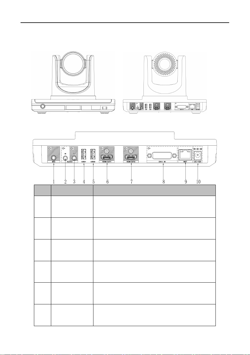
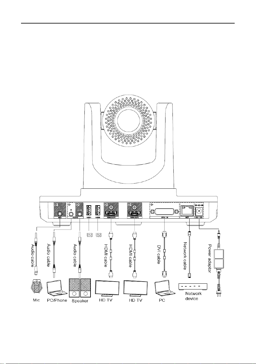
Audio Input: connect a microphone to the MIC by using a XLR adapter.
Audio Device Input: connect an audio device to AUDIO IN by using a 3.5 headphone cable.
Primary Video Output: connect an external display device to HDMI OUT1 by using a HDMI cable.
Audio Output: connect an external display device to HDMI OUT1 by using a HDMI cable or
connect a speaker to AUDIO OUT by using a 3.5mm audio cable.
Secondary Video Output: connect an external display device to HDMI OUT2 by using a HDMI
cable.
Network Connection: use a network cable to connect network port for Internet access.
Power Supply Connection: connect a power adapter to the DC+12V connector and a power
socket.
Power On
Please connect all devices to the terminal before switching on power supply.
Attention:
Do not let the power supply cable detach from the terminal in order to avoid power shortage when
it is powered on.
Please turn off the terminal before cutting off external power supply (e.g. socket power). Please
check if power cables and power adapters are correctly connected to related devices.
Please make sure the AC voltage range is within 100V-240V and frequency is 50Hz or 60Hz.
The sequence of live line, null line and PE should be in right order and related voltage tolerance
should be within international standard. PE should be properly linked to the ground.
Arrange cable layouts in accordance with the above picture and connect adapter to power supply by
using HDMI OUT1 as output interface, a. Press POWER button (green indicator always lit), the
terminal is turned on and main menu will show up.
After the terminal is turned on, its indicators are shown as below:

9
Status Description
Green power indicator always lit Work in progress
Orange power indicator always lit System turned off but power supply
still on
Power indicator off Power supply cut off
Infrared indicator flashes green Receiving infrared signals
Basic Info
Language Setup
1. Select “Settings” in the main menu and enter “Settings->Network->Network
Settings->Language” for different language settings.
2. Select “English”, “Chinese (CN)”, “Chinese (TW)”, “Polish” or “Japanese” and return to setting
menu.
Time and date setup
1. Select “Settings” in the main menu and select “Network” for network setup.
2. Move down the menu and select “Time and Date” for time setup.
Parameters Descriptions
Time Zone Set up time zone in the user’s area.
Time Server Set up NTP time server.
Auto Synch Set up auto synch
24-hour format Set up 24-hour format
Date Format Set up sequence of day, month and year
Back Save setup and back to network
Network Setup
1.Select “Settings” in the main menu and select “Network” for setup.
2.Select “Ethernet Settings”

10
Parameters Descriptions
Network Type Manual Setup: enter the IP, mask and gateway address distributed by
IP IP address
Mask Mask address
Gateway Gateway address
DNS Domain Name Server
Save Save network settings and get back
Cancel Cancel network settings and get back
System Account Settings
1. Select “Settings” in the main menu and select “Account”.
Select “Display Name”, enter “System Name” and select “Save”.
H.323 account Settings (optional)
Set up the terminal’s H323ID and number. Specify GK address and get GK registered in order to use a set of
numbers to start conference calls or other communications.
1. Select “Settings” in the main menu and select “Account” for account setup.
2. Select “H.323 account” and confirm for further setup.

11
Parameters Descriptions
Setup Mode Manual setup, Zijing Cloud
Zijing Cloud In this mode, enter correct Zijing Cloud account and password to
automatically acquire H.323 info.
Manual
Settings
GK Server IP address or DNS of GK
Register Name
Set up registered account or name
No. Other names of the terminal or E.164 number (optional)
Password GK register password setup
Save Save settings and return to setting menus.
Only when GK is active, the terminal can be registered; otherwise the terminal
will not be
Note:
1. If GK is activated, the account will be registered in GK after system starts. After the terminal is
successfully registered, users can use it for conference call.
2. If GK is not activated, the terminal will not be registered in GK and can only make conference call
through IP address.
SIP Account Settings (Optional)
Set up SIP parameters and SIP address for remote interactions through registered numbers.
1. Select “Settings” in the main menu and select “Account” for setup.
2. Select “SIP Account” and confirm for further setup.

12
Parameters Descriptions
Setup Mode Manual setup, Zijing Cloud
Zijing Cloud In this mode, enter correct Zijing Cloud account and password to
automatically acquire SIP info
Manual
Settings
Protocol TCP, UDP, optional
SIP Proxy server IP or DNS of SIP proxy server (optional)
User Name Set up user name or SIP URI
User Name Set up User Name Authentication (optional)
Password Set up Password Authentication (optional)
Domain Set up Domain Authentication
Save Save setups and return to setting menu
The terminal can only register SIP server when SIP is active; otherwise the terminal will not be
registered or log off from SIP server.
Table of contents
Popular Conference System manuals by other brands

Clear One
Clear One COLLABORATE Versa Room CT quick start guide

Wyrestorm
Wyrestorm NHD-0401-MV quick start guide

Clear One
Clear One CLOCKAUDIO TS-001 Tech note

Clear One
Clear One XAP 800 Installation and operation manual

Clear One
Clear One Converge 560 user manual

Clear One
Clear One Aura Xceed BMA quick start guide