INSTRUCTIONS MANUAL
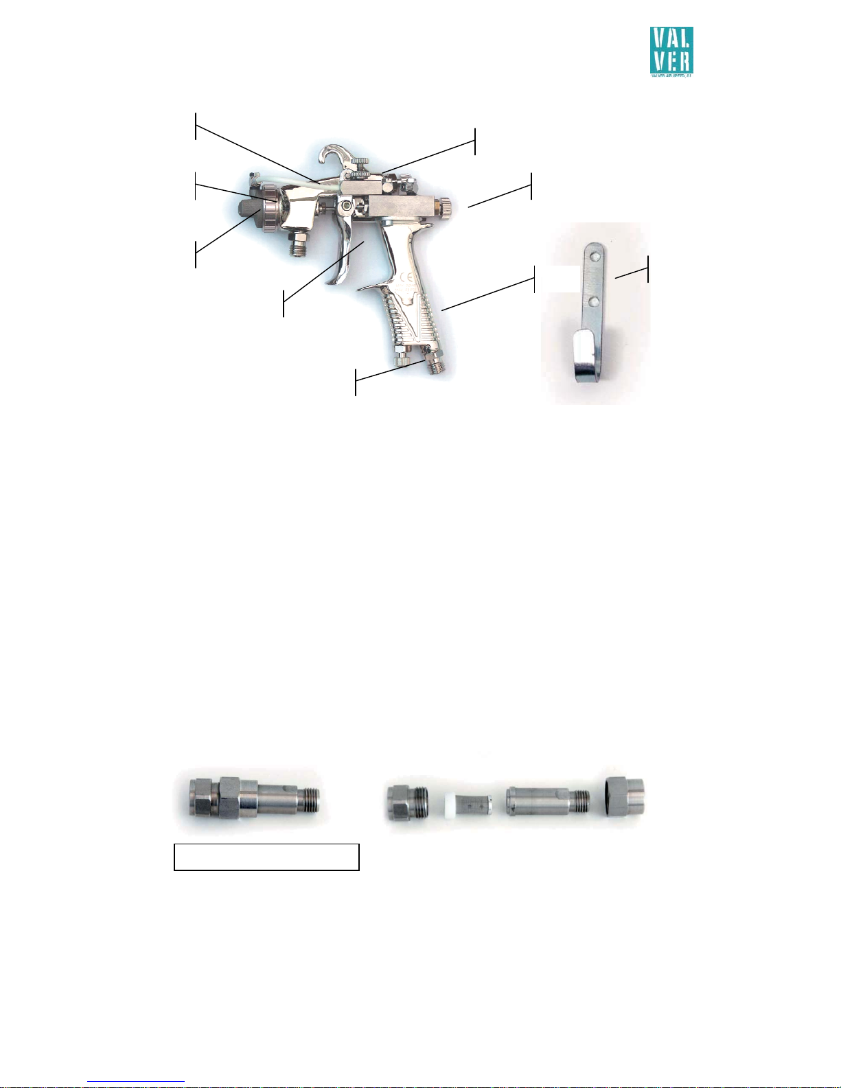
AIRBRUSH MANUAL EXTERNAL MIX EQUIPMENT
4
NAME: _________________________________________________________________________________________
COMPANY NAME: ____________________________________________________________________________
ADDRESS: _________________________________________________________________________________
MODEL OF MACHINE: _______________________________________________________________________
SERIAL NO.: ______________________________________________________________________________
DATE: _________________________________________________________________________________
STAMP AND SIGNATURE:
___ ___ ___ ___ ___ ___ ___ ___ ___ ___ ___ ___ ___ ___ ___ ___ ___ ___ ___ ___ ___ ___ ___ ___ ___
Description: AIRBRUSH MANUAL EXTERNAL MIX EQUIPMENT
Model:
Serial nº:
All equipment has 2 years warranty from the date of the invoice: The warranty covers the replacement
or repair of the machine’s components and Valver Air Speed S.L.’s acknowledgement that they are faulty due to
manufacturing errors, in addition to the labour involved in the replacement and/or repair of parts. Service during
the warranty will only be valid if it is carried out by Valver Air Speed S.L. in its own workshops.
The materials will be sent with the postage paid and once the machinery has been repaired it will be
returned to the client, who must pay for the postage. The warranty does not include our engineers working in the
place where the machine is installed or the dismantling of the machinery. If it is absolutely necessary to send
Valver Air Speed S.L. staff out, it will always be done at their own discretion and an invoice will be issued for the
job plus the travelling expenses.
This warranty will only be valid if it is signed, stamped and dated by Valver Air Speed S.L. and it must
also be accompanied by the receipt of purchase for the machine under warranty.
The warranty does not include:
-Compensation for either direct or indirect damage caused by our machines to objects or people. Likewise, it
does not include repairs carried out by the client or by third parties.
-Breakdowns caused by inappropriate use or assembly.
-Breakdowns caused by outside agents.
-Breakdowns due to negligence or insufficient maintenance.
-Damage caused by neglect, incompetence, running wear, not having used the appropriate cleaning solvent
or poor maintenance or use of the machine.
The warranty will lose validity in the event of default on payments or other forms of non-compliance
with the contract. Repairs carried out during the warranty period do not reduce or increase its duration. The
warranty will also lose validity if the machine is handled without our authorisation, or if the machine is
dismantled in another workshop. The guaranty will be void if the serial no. is erased or tampered with, or when
the damage arises from inappropriate operation or use, from negligence, knocks, falls and other reasons that are
not a result of its normal operation.
Both parties agree to submit any legal dispute or conflict to the Courts of the city of Valencia, expressly
renouncing any corresponding rights with regard to other jurisdiction.
Valencia,
VALVER AIR SPEED, S.L.