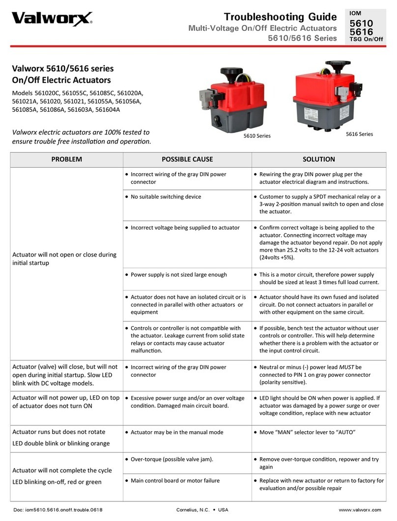
Valworx 561020C User manual

Doc: iom5610.5616.dps.trouble.0618 Cornelius, N.C. • USA www.valworx.com
Troubleshooting Guide
Electric Actuators with DPS Positioner
5610/5616 Series
IOM
5610
5616
TSG DPS
Valworx 5610/5616 series Electric Actuators
with Oponal DPS Posioner
Models 561020C, 561055C, 561085C, 561020A, 561021A,
561020, 561021, 561055A, 561056A, 561085A, 561086A,
561603A, 561604A
Valworx electric actuators are 100% tested to ensure
trouble free installaon and operaon.
PROBLEM POSSIBLE CAUSE SOLUTION
Actuator will not open or close during
inial startup
Incorrect voltage or power connecon. Conrm correct voltage is being applied to gray
connector and power connecon is wired
correctly. Neutral or negave (-) must be
connected to PIN 1. Do not apply more than 25.2
volts to the 12-24 volt actuators (24volts +5%).
Incorrect control signal input. This must be an
industry standard analog input control signal.
Do NOT connect a baery or variable power
supply directly to the control signal input. This
will damage the control circuit board.
Conrm actuator is setup for correct input (4-
20mA or 0-10vdc). Conrm control signal wiring is
correct per wiring diagram and instrucons
Undersized power supply This is a motor circuit, therefore power supply
should be sized at least 3 mes full load current.
Actuator does not have an isolated circuit or is
connected in parallel with other actuators or
equipment
Actuator should have its own fused and isolated
circuit. Do not connect actuators in parallel or
with other equipment on the same circuit.
Controls or controller is not compable with
the actuator
If possible, bench test the actuator without user
controls or controller. This will help determine
whether there is a problem with the actuator or
the input control circuit.
Actuator will not power up, LED on top
of actuator does not turn ON
Excessive power surge and/or an over voltage
condion. Damaged circuit board.
LED light should be ON when power is applied. If
actuator was damaged by a power surge or over
voltage condion, replace with new actuator
Actuator runs but does not rotate
LED double blink or blinking orange
Actuator may be in the manual mode Move “MAN” selector lever to “AUTO”
Actuator will not complete the cycle
5610 series LED blinking on-o, on-o
5616 series LED blinking red or green
Over-torque (possible valve jam). Remove over-torque condion, repower and
retry
Main control board or motor failure Replace with new actuator or return to factory for
evaluaon and/or possible repair
Actuator powers ON but will not
complete cycle
Control board or motor failure Replace with new actuator or return to factory for
evaluaon.
Manual override selector lever in ‘AUTO’ mode Move manual override selector to ‘MAN’ mode
Cannot turn the manual override knob
Excessive force applied to manual override
knob, this may have damaged the gear drive
If aer selecng ’MAN’, manual override sll does
not work, replace with a new actuator
Valve jam Clear valve jam and try again
5616 series5610 series

2
Doc: iom5610.5616.dps.trouble.0618 Cornelius, N.C. • USA www.valworx.com
Troubleshooting Guide
Electric Actuators with DPS Positioner
5610/5616 Series
IOM
5610
5616
TSG DPS
PROBLEM POSSIBLE CAUSE SOLUTION
Actuator fails to operate and condensaon
or water is found inside the actuator
DIN plug connectors are loose, missing or have
damaged seals. Connector seals installed
incorrectly.
Inspect seals and replace if necessary. Make sure
seals are installed correctly and ghten DIN
connector screws securely (0.4 to 0.5Nm).
Built in heater was not acvated connuously Power must be maintained ‘ON’ to acvate
internal heater. This heater will help prevent
condensaon buildup inside the actuator. If the
actuator has failed due to excessive condensaon
or water inside the actuator, replace with a new
actuator.
Actuator fails and excessive black dust
and/or corrosion is found under the red
cover
Excessive condensaon or water inside
actuator. Highly corrosive environment,
saltwater, chemicals, other.
If the actuator has failed due to excessive black
dust or corrosion inside the actuator, typically it is
non-repairable and must be replaced with a new
actuator.
Black dust from motor brush wear may be
caused by exceeding the 75% duty rang of the
actuator.
Actuator must operate within the 75% duty cycle
rang. Typically, this means the motor can be
running for 45 seconds, then must be o for 15
seconds of each minute.
Actuator is worn out Replace with a new actuator
No output signal from posion
conrmaon limit switches
Switches are wired incorrectly Check the switch wiring and make sure the
common for limit switches is on PIN 1. If checking
connuity, you should have connuity between
PIN 1 and 2 when actuator is closed and
connuity between PIN 1 and 3 when open. No
connuity when actuator is moving in between
closed and open posions.
Exceeding the current capacity has damaged
the limit switch. Switch rang 3 amps @
125/250VAC, 30VDC resisve load.
Damage to the limit switches is not a eld
repairable item. Either return actuator to the
factory for possible repairs or replace with a new
actuator.
Limit switch cams are out of adjustment. Limit switch cams can be adjusted if necessary.
Contact customer service for Service Procedure.
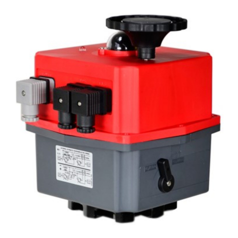
Manual Override
Selector Lever
MAN: Manual Mode
AUTO: Automac Mode
Visual Posion
Indicator (shown in
open posion)
LED Power On and
Diagnosc Light
Manual Override
Knob
DIN Plug Connectors

3
Doc: iom5610.5616.dps.trouble.0618 Cornelius, N.C. • USA www.valworx.com
Troubleshooting Guide
Electric Actuators with DPS Positioner
5610/5616 Series
IOM
5610
5616
TSG DPS
Electrical Wiring Diagram for 5610/5616 series
Actuators with DPS Posioner
DIN Plug Connectors
1.Seal
2.Screw terminal block (Pins 1, 2, 3 & G)
3.Connector housing
4.Retainer screw
5.Cable retainer gland
Wiring: Main Power Connecon
Power is connected to the actuator via the
large gray DIN plug connector. Wires are
connected to screw terminals located inside
the connector.
Power: connect to PIN 1 and PIN 2
Ground: connect at pin on DIN connector to
earth ground
Notes:
1. The Neutral (AC voltages) or Negave (DC voltages
must be connected to PIN 1.
2. Power should be maintained to acvate the
internal heater. This heater will help prevent
condensaon build up inside the actuator.
3. Actuator should have it’s own fused and isolated
circuit. Do not connect actuators in parallel or on the
same circuit with other equipment.
4. Supply voltage to 24 volt actuators should not
exceed 25.2 volts (24 volts +5%).
Wiring: Analog Control Signal
Signal Input:
Connect Negave (-) input to PIN 1
Connect Posive (+) input to PIN 2
Signal Output (posion monitoring signal):
Connect to PIN 3
Note: The signal output (use of output is oponal) will
be in the same format as the input. ex: 4-20mA input,
4-20mA output or 0-10v input, 0-10v output. Nominal
impedance 100 ohms (4-20mA), 13K ohms (0-10v). Do
not connect ground PIN on control signal plug.
Wiring: Posion Conrmaon Limit
Switches
Two auxiliary dry contact limit switches are
provided to conrm the valve open and closed
posion. Use of these switches is oponal.
Limit Switch Rang 3A@125/250 VAC, 30VDC
resisve load
PIN 1: Common
PIN 2: Signal to conrm Closed Posion
PIN 3: Signal to conrm Open Posion
Note: Using the posion conrmaon switches is
oponal and not required for actuator to funcon
correctly.
Before connecting
power, confirm
correct voltage is
being applied
Wiring I.D. for Optional Prewired DIN Cables
PIN 1 - Brown PIN 3 - Black
PIN 2 - Blue GROUND - Green/Yellow
12
Power Connecon
LS1
OPEN
Signal
LS2
CLOSED
Signal
Posion Conrmaon
Limit Switches
12
3
N / -
L / +
LS1
N / -
LS2
N / -
COM
L / +
Earth
Ground
DPS Posioner
21
3
+ -
Input
+
Output
Power
VAC or VDC
Power Plug
Signal Input
Posion Switches

4
Doc: iom5610.5616.dps.trouble.0618 Cornelius, N.C. • USA www.valworx.com
Valve Misapplicaon
Somemes electric actuated valves may fail due to misapplicaon or using the valve in the wrong applicaon. Reviewing
and complying with the product specicaons will ensure long-term trouble free operaon. Specicaons can be found
online or in the product data sheet. Customers that connue to have problems will an actuator will usually indicate one
of two things. Either the actuated valve is unsuitable for the applicaon or it’s not in compliance with one or more of the
following issues:
Voltage: The voltage must be within the operang range of the actuator.
Over voltage or under voltage may cause premature failure.
Temperature: Operang outside the temperature rang will shorten the
life and ulmately cause the actuator to fail. Valworx 5610/5616 series actua-
tors must operate within the range of -4 to +158°F (-20 to +70°C).
Environment: The 5610/5616 series actuators have an IP67 weather-
proof rang. Generally suitable for indoor or outdoor applicaons. Provides a
degree of protecon against rain, splashing water and hose directed water
(Do not pressure wash). Protecng the actuator against rain, snow, ice and UV
(sun light) will typically extend the life of the product. Highly corrosive
environments may cause premature failure of electronic components. Do not
use these actuators where explosion proof equipment is required.
Duty Cycle: Exceeding the 75% duty cycle rang of the 5610/5616 series
actuators will cause premature failure of the motor and/or electronic boards.
This is very important when using the DPS posioner opon. The motor
should not move for at least 25% of the me (or typically 15 seconds of each
minute).
Fluid Media: The valve materials of construcon should be compable
with the media (uid) owing through the valve. This would include all weed
parts or parts in contact with the media. Contacng the manufacturer of the
uid or consulng a media compability guide may be helpful. Ball valves and
buery valves generally require good clean owing media.
Pressure: Valves must operate within the pressure rang as listed in the
specicaons. The pressure rang is typically the highest non-shock working
pressure allowed within certain temperature limits. Reference the P/T chart
(pressure/temperature chart) to conrm the valve will operate within the
required pressure and temperature limits.
Fluid Velocity: The uid velocity should not exceed certain limits to help
avoid excessive noise, shock and damage to the piping system, seals and
valves. Typically, the maximum velocity of the uid owing through Valworx
metal valves should be less than 10 feet/second (3 m/s). The maximum veloci-
ty for plasc valves should be less than 5 feet/second (1.5 m/s).
Troubleshooting Guide
Electric Actuators with DPS Positioner
5610/5616 Series
IOM
5610
5616
TSG DPS
This manual suits for next models
12
Other Valworx Controllers manuals
Popular Controllers manuals by other brands

NI
NI cRIO-9081 Getting started

Bosch Thermotechnology
Bosch Thermotechnology MBC 2 manual

LumaSense technologies
LumaSense technologies Innova Type 1314i instruction manual

SOMFY
SOMFY Situo 1 RTS instructions

Omron
Omron CJ - PROGRAMMING 12-2009 Programming manual

steute
steute RF Rx SW868-NET-4S-A Mounting and wiring instructions