VAMP 120 User manual

VAMP 120
Arc protection unit
User manual

VAMP 120
Arc protection unit
User manual
VAMP Ltd
2
VAMP 24h support phone : +358 (0)20 753 3264
VM120 EN001

VAMP Ltd Arc protection unit
User manual
VAMP 12
0
VM120 EN001 VAMP 24h support phone : +358 (0)20 753 3264
3
Table of content
1. General ...................................................................................4
1 1 Arc protection unit VAMP 120 4
1 2 Unit features 4
2. Unit configuration...................................................................5
3. Sensors ....................................................................................6
3 1 Arc sensor VA 1 DA 6
4. unctions .................................................................................8
5. Applications............................................................................9
6. Connections .........................................................................10
7. Technical data .....................................................................12
Auxiliary voltage 12
Tripping contacts 12
BIO Input 12
Disturbance tests 12
Voltage tests 13
Mechanical tests 13
Environmental conditions 13
8. Dimensions............................................................................14
8 1 VAMP 120 14
8 2 VA 1 DA arc sensor 15
8 3 Mounting plates for VA 1 DA 15
9. Order information.................................................................16
10. Reference information.........................................................17

VAMP 120
Arc protection unit
User manual
VAMP Ltd
4
VAMP 24h support phone : +358 (0)20 753 3264
VM120 EN001
1. General
This manual describes the general functions of the arc
protection unit, it also includes mounting and configuration
instructions.
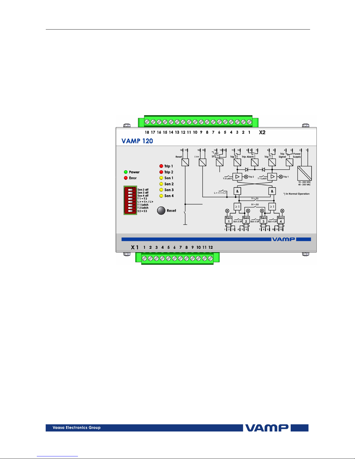
1.1. Arc protection unit VAMP 120
Figure 1.1-1. Arc protection unit VAMP 120
1.2. Unit features
VAMP 120 is a state of the art arc protection unit for electrical
po er distribution systems.
By using VAMP 120 in s itchgears considerable safety
improvements are obtained in the form of minimized injury and
damage in case of an arc fault.
VAMP 120 is a “stand alone” system, hich gives a compact
solution hen the application doesn’t require overcurrent
measurement or hen the overcurrent information is available
from the incomer protection relay or any other arc protection
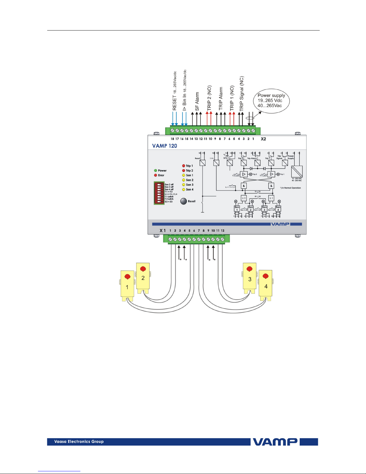
unit (VAMP 221 / VAM 4C). It is possible to connect 4 arc
sensors, of the type VA 1 DA or VA 1 EH, to the VAMP 120
unit.

VAMP Ltd Arc protection unit
User manual
VAMP 12
0
VM120 EN001 VAMP 24h support phone : +358 (0)20 753 3264
5
2. Unit configuration
Figure 2-1. VAMP 120 dips itch operations and sensor connection
The unit is configured using the dips itches:
Dipswitches 1-5 (see igure 2-1):
If only one arc sensor in use, SENSOR 1 input should be used.
•
SW nr. 1 : if sensor input 2 is also required, SEN 1
should be set to the left position.
•
SW nr. 2 and 3 :
if sensor input 3 and 4 are used, SW nr. 2
and 3 should respectively be set to left
position.
•
SW nr. 4 : is setting the system selectivity. If set to
the left position, sensor nr. 1 and 2 ill
trip relay T1. Accordingly sensor nr. 3 and
4 ill trip relay T2. The NC trip signal
out put ill al ays ork in parallel ith
T1. If SW nr. 4 is to the right, all four
sensor channels ill activate both trip
groups.
•
SW nr. 5 : is the selection of tripping criteria. If set
to the right, the unit ill trip for light
only. If set to the left, the unit needs both
light and current information for tripping.
•
SW nr. 6 and 7 :
the Latch s itches enables latching of the
trip relays. When it is in ON position the
latching function is activated.
•
SW nr. 8 : is the configuration s itch for sensor
inputs 2 and 3. If it is in “ON” position,
sensor 2 or 3 activation ill make a
common trip of both T1 and T2. If it is in
“OFF” position, sensor 2 is linked to T1
and sensor 3 to T2.

VAMP 120
Arc protection unit
User manual
VAMP Ltd
6
VAMP 24h support phone : +358 (0)20 753 3264
VM120 EN001
3. Sensors
3.1. Arc sensor VA 1 DA
The arc sensor is a light sensitive element, hich is activated
by strong light. Arc sensors should be mounted in the s itch-
gear cubicles, in such a ay that the light sensitive part (see
Figure 3.1-2) covers the protected area as completely as
possible.
Figure 3.1-1. Arc sensor VA 1 DA
40 30 20 10 0
50
60
70
80
90
100
120
130
140
100%
80
60
40
20
Figure 3.1-2. The sensitivity of the VA1DA arc sensor to light from different
directions.
In open spaces, such as the bus bar section, arc sensors should
be mounted max. four meters apart.
The light sensitivity of the arc sensor is 8000 LUX
The arc sensor can be mounted from the outside on partition
all of the s itchgear. The active part of the sensor is mounted
in a 10 mm hole, to the area in the s itchgear that should be
protected, and fastened ith a 4 mm self-tapping scre (see
Figure 3.1-3).

VAMP Ltd Arc protection unit
User manual
VAMP 12
0
VM120 EN001 VAMP 24h support phone : +358 (0)20 753 3264
7
The arc sensor can alternatively be mounted completely in the
protected area ith the help of a mounting plate VYX 01 (Z-
shaped) or VYX 02 (L-shaped). (See Figure 8.3-1)
10mm
Fastening screw 4 x 15
Active part of the sensor
Anchoring
Sensor cable
Figure 3.1-3. Arc sensor mounting picture.

VAMP 120
Arc protection unit
User manual
VAMP Ltd
8
VAMP 24h support phone : +358 (0)20 753 3264
VM120 EN001
4. unctions
VAMP 120 includes an extensive self-supervision. The self-
supervision includes internal functions as ell as all arc
sensors.
Figure 4-1. Self-supervision block diagram
If an internal fault occurs the self-supervision relay is activated
and the ERROR-led is lit.

VAMP Ltd Arc protection unit
User manual
VAMP 12
0
VM120 EN001 VAMP 24h support phone : +358 (0)20 753 3264
9
5. Applications
Every compartment is equipped ith an arc sensor. Up to four
sensors can be connected to the VAMP 120 unit. The trip relays
are electromechanical and can be connected directly to control
the circuit-breakers (see chapter Technical data).
The VAMP 120 is suitable for small po er generation plants
here light is the only criteria for tripping and full selectivity
is required.
Figure 5-1 Wind po er application
Figure 5-2 Diesel po er plant application

VAMP 120
Arc protection unit
User manual
VAMP Ltd
10
VAMP 24h support phone : +358 (0)20 753 3264
VM120 EN001
6. Connections
*Connection for shield if shield sensor cable used (VA1DA-20s)
Figure 6-1. VAMP 120 connection
The VAMP 120 unit comprises t o independent arc protection
zones. Both zones have their o n trip relay, trip 1 and trip 2.
Trip 1 is controlled by sensor inputs 1 and 2. Trip is controlled
by sensors 3 and 4.
Trip alarm is activated if either or both are tripping. If “T1=T2”
dip s itch is at “on” position, both trip outputs ill ork in
parallel for any sensor activation.
If “S1=S2” dip s itch is at “on” position, sensors 2 and 3
activation ill cause both T1 and T2 to trip. This is e.g. used for
CB compartment supervision here t o zones are overlapping
each other.

VAMP Ltd Arc protection unit
User manual
VAMP 12
0
VM120 EN001 VAMP 24h support phone : +358 (0)20 753 3264
11
If overcurrent criteria is required simultaneously ith light
activation, a binary current signal has to be connected to X2-
15/16. This I> signal can e.g. be taken from a VAM 4C or
VAMP 221 unit. The external reset is possible by correcting an
auxiliary voltage to X2-17/18.
The auxiliary boltage is connected to X2-1 and X2-2. VAMP has
a ide range po er supply from 19 to 265 Vdc or 40 to 265 Vac
in the same hard are.

VAMP 120
Arc protection unit
User manual
VAMP Ltd
12
VAMP 24h support phone : +358 (0)20 753 3264
VM120 EN001
7. Technical data
Auxiliary voltage
Us 19 … 265 V dc / 40 … 265 V ac
In (stby) 30mA
IsensAct 20mA
Iarc 120mA + (IsensAct x n);
n = number of active sensors
Tripping contacts
Number 1
Rated voltage ≤250V ac/dc
Continuous carry 5A
Make and carry for 0.5s 30A
Make and carry for 3s 15A
Breaking capacity DC, hen time
constant L/R=40ms
50W
Contact material AgCdO2
Operating time 7ms
BIO Input
Rated voltage 18 - 265 Vac/dc
Rated current / input 5 mA
Number of inputs 2
Disturbance tests
EMC test CE approved and tested according to EN
50081-2, EN 50082-2
Emission
- Conducted (EN 55011 class A) 0.15 - 30 MHz
- Emitted (EN 55011 class A) 30 - 1 000 MHz
Immunity
- Static discharge (ESD) (According to
IEC244-22-2 and EN61000-4-2, class III)
Air discharge 8 kV
Contact discharge 6 kV
- Fast transients (EFT) (According to
EN61000-4-4, class III and IEC801-4, level 4)
Po er supply input 2kV, 5/50ns
other inputs 2 kV, 5/50ns
- Surge (According to EN61000-4-5 [09/96],
level 4)
Bet een ires 2 kV / 1.2/50µs
Bet een ire and earth 4 kV / 1.2/50µs
- RF electromagnetic field test (According. to
EN 61000-4-3, class III)
f = 80….1000 MHz 10V /m
- Conducted RF field (According. to EN 61000-
4-6, class III)
f = 150 kHz….80 MHz 10V

VAMP Ltd Arc protection unit
User manual
VAMP 12
0
VM120 EN001 VAMP 24h support phone : +358 (0)20 753 3264
13
Voltage tests
Insulation test voltage acc- to IEC 60255-5
2 kV, 50Hz, 1min
Impulse test voltage acc- to IEC 60255-5 5 kV, 1.2/50us, 0.5J
Mechanical tests
Vibration test 2 ... 13.2 Hz ±3.5mm
13.2 ... 100Hz, ±1.0g
Shock/Bump test acc. to IEC 60255-21-2 20g, 1000 bumps/dir.
Environmental conditions
Specified ambient service temp. range -35…+70°C
Transport and storage temp. range -40…+70°C

VAMP 120
Arc protection unit
User manual
VAMP Ltd
14
VAMP 24h support phone : +358 (0)20 753 3264
VM120 EN001
8. Dimensions
8.1. VAMP 120
Figure 8.1-1. Arc protection unit VAMP 120 dimensions

VAMP Ltd Arc protection unit
User manual
VAMP 12
0
VM120 EN001 VAMP 24h support phone : +358 (0)20 753 3264
15
8.2. VA 1 DA arc sensor
25
14
22
4
10
Figure 8.2-1. VA 1 DA arc sensor dimensions
8.3. Mounting plates for VA 1 DA
50
10 m m
3m m
44
59
25 15 15
26
50
50
30
10 mm
3 mm
44
59
15 15
26
30
VYX 001 VYX002
Figure 8.3-1. Mounting plate dimensions.

VAMP 120
Arc protection unit
User manual
VAMP Ltd
16
VAMP 24h support phone : +358 (0)20 753 3264
VM120 EN001
9. Order information
Unit
UnitUnit
Unit
Ordering code
Ordering codeOrdering code
Ordering code
VAMP 120 unit VAMP 120
Installation kit for flush mounting VB 263
Arc sensor, 6 m cable VA 1 DA-6
Arc sensor, 6 m cable VA 1 EH-6 (1P65)
Arc sensor, 20 m cable VA 1 DA-20

VAMP Ltd Arc protection unit
User manual
VAMP 12
0
VM120 EN001 VAMP 24h support phone : +358 (0)20 753 3264
17
10. Reference information
Manufacturer data:
VAMP Ltd
P.O.Box 810
FIN-65101 Vaasa, Finland
Visiting address: Yrittäjänkatu 15
Phone: +358 (0)20 753 3200
Fax: +358 (0)20 753 3205
Service:
VAMP Ltd
P.O.Box 810
FIN-65101 Vaasa, Finland
Visiting address: Yrittäjänkatu 15
Phone: +358 (0)20 753 3200
Fax: +358 (0)20 753 3205
24h support phone:
Tel . +358 (0)20 753 3264
Email: [email protected]

VM120 EN001
VAMP Ltd Street address: Yrittäjänkatu 15 Phone: +358 20 753 3200
Post address: Fax: +358 20 753 3205
Box 810, FIN 65101 Vaasa, Internet: www vamp fi
Finland Email: vamp@vamp fi
We reserve the rights to changes without prior notice
Table of contents
Popular Power Distribution Unit manuals by other brands

NetPing
NetPing NP-SM4 user guide

Netio
Netio PowerPDU 8QS QIG Quick installation guide

aldes
aldes InspirAIR Home Series Installation and maintenance guide

Crestron
Crestron CAEN-BLOCK-CENCN-2-POE Installation & operation guide

Emerson
Emerson Liebert MPX PRC Mounting Options

GÜDE
GÜDE Expert Power Control 8291 manual