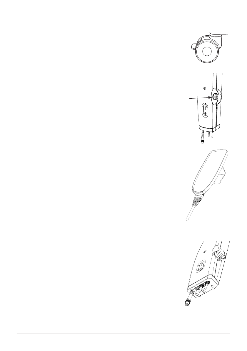
Vancare VanGo 600 User manual

Mobile lift VanGo 600 has been developed to meet most lifting needs in combination with the right accessories. It
is a lift that can lift patients in a seated or supine position. VanGo600 is made largely of aluminum, which makes it
relatively light, considering the weight it can lift.
Visual inspection
Inspect lift functions regularly. Check to ensure that material is free from damage.
Before use:
Ensure that the product is correctly assembled.
Check slingbar connection and safety latch function.
Check lift and base-width movement.
Check to ensure that the actuator is correctly installed.
Always read the manuals for all assistive devices used during a transfer.
Keep the manual where it is accessible to users of the product.
The lift may only be used by persons who have received instruction in the operation of the lift.
Functional inspection
Always read the manual
Manual - English
1. Boom
2. Mast
3. Handlebar
4. Battery pack
5. Emergency stop
6. Control box
7. Motor for base-width adjustment (model EE)
8. Rear castors with brakes
9. SlingBar with safety latch
10. Front castors
11. Emergency lowering
12. Motor/actuator for boom
13. Mast height adjustment
14. Base-width adjustment pedal (model EM)
SWL: 600Ibs
VANGO 600
1
2
3
4
5
6
7
8
9
10
11
12
13
Eva450EEL Eva600EEL
Eva450EML
REVISION HISTORY
REV.
DESCRIPTION
DATE
APPROVED
D
E
F
C
1
2
3
4
B
A
3
2
1
5
C
D
4
6
7
8
A
B
SCALE:1:10
DWG. NO.
REV.
NAME
DATE
DRAWN
APPROVED BY
SHEET 1 OF 1
WEIGHT:
COMMENTS:
STATUS:
TITLE
MATERIAL:
SIZE
Released
EVA EEL 450 base
90001288 02
g
2011-05-20
A3
Unless otherwise stated, general
tolerances according to ISO 2768-m
hc-jope
This drawing and any information or descriptive matter set out hereon are the confidential and copyright property of Handicare
and must not be disclosed, loaned, copied or used for manufacturing, tendering or any other purpose without their written permission.
14

Table of contents
Assembly.......................................................................................... 3
- Final inspection..................................................................................... 4
Using the product ......................................................................... 5
- Important information ........................................................................... 5
- Safe working load ................................................................................. 5
- Charging batteries................................................................................. 6
- Handset................................................................................................ 6
- Base-width adjustmentt......................................................................... 6
- Emergency stop .................................................................................... 7
- Emergency lowering .............................................................................. 7
- Brakes ................................................................................................. 7
- Trouble shooting.................................................................................... 8
Accessories.................................................................................... 9
Maintenance ..................................................................................10
Technical information ................................................................11
- Dimensions .....................................................................................12-13
2

Assembly
Check to ensure that all components are included:
Mast with boom, lift motor, carry bar, control box and battery pack.
Base with motor and locking handle. Handset and cord.
Instructions, charger with cable and adapter for wall socket.
Place the mast in the base. There are three alternatives for adjusting the height of the
mast. Secure the mast with the locking handle.
Mount handlebar with two wrenches.
Connect the cables to the control box. Cable to actuator (motor on mast) to outlet
1. Mount the cover for the cables using the two screws.
Release the emergency-stop mechanism and perform a final inspection (see final
inspection).
Handset
cover
for the
cables
3
1

Final inspection
Check to ensure that no parts have been left in the packaging.
Inspect the lift for signs of wear and damage.
Check all four castor wheels and caster wheel locks.
Check all connections and fixtures including screws and bolts.
Check the emergency stop function by depressing the emergency stop, and then
pressing either the up or down button. If nothing happens when the up or down
buttons are pressed, the emergency stop is functioning properly.
Grasp the handset, press the up button and run the lift arm all the way up. Then, press
the down button and run the lift arm all the way down.
Test base-width adjustment function.
Test base-width adjustment function on the VanGo 400 by pushing down on the
respective pedals for widening and narrowing the base.
Test lift function by lifting a person (not a patient) using an approved sling. At the same
time, check the emergency lowering function with someone on the lift. See section on
Emergency lowering.
If the lift is functioning correctly, connect the charger and check to ensure that the
charging lamp on the control box lights up.
NOTE!
Before the lift is used for the first time, it must be charged for at least 4 hours. See
section on charging batteries.
Keep the manual where it is accessible to users of the product.
4

• The lift must be assembled according to the assembly instructions provided with the lift.
• The lift may only be used indoors and on a level floor.
• When lifting from the floor the rear wheels must always be locked to prevent the lift from rolling and colliding with the
patient’s head. Otherwise, the wheels should not be locked, so that the lift can align itself with the patient’s center
of gravity.
• Lifting accessories must be properly trial fitted and tested in relation to the patient’s needs and functional ability.
• Do not leave the patient unattended during a transfer situation.
• Under no circumstances may max. load be exceeded. See section on Safe working load.
• Never move the lift by pulling on the actuator!
• The lift must not come in direct contact with water.
• The lift must not be charged in a wet room.
• To ensure optimal function, the lift must be inspected regularly. See section on Maintenance.
• Warranty applies only if repairs or alterations are done by an authorized technician.
Do not push
Important Information
Using the product
Safe working load
Different products on the same lift system (lift unit, slingbar, sling, scales and other lifting accessories) may have different
allowable safe working loads. The lowest allowable safe working load always determines the safe working load of the
assembled system. Always check the safe working loads for the lift and accessories before use. Contact your dealer if
you have any questions.
5

Charging batteries
A tone when using the lift indicating that the batteries need recharging.
Lock the casts when charging the battery.
Make sure the emergency stop button is not pressed in.
Charging procedure:
1. Connect the charger to the charger cable leading from the underside of the control
box.
2. Connect the charger to a power outlet (100-240 V AC).
3. When the charger is connected, the control box lamp indicates a yellow light.
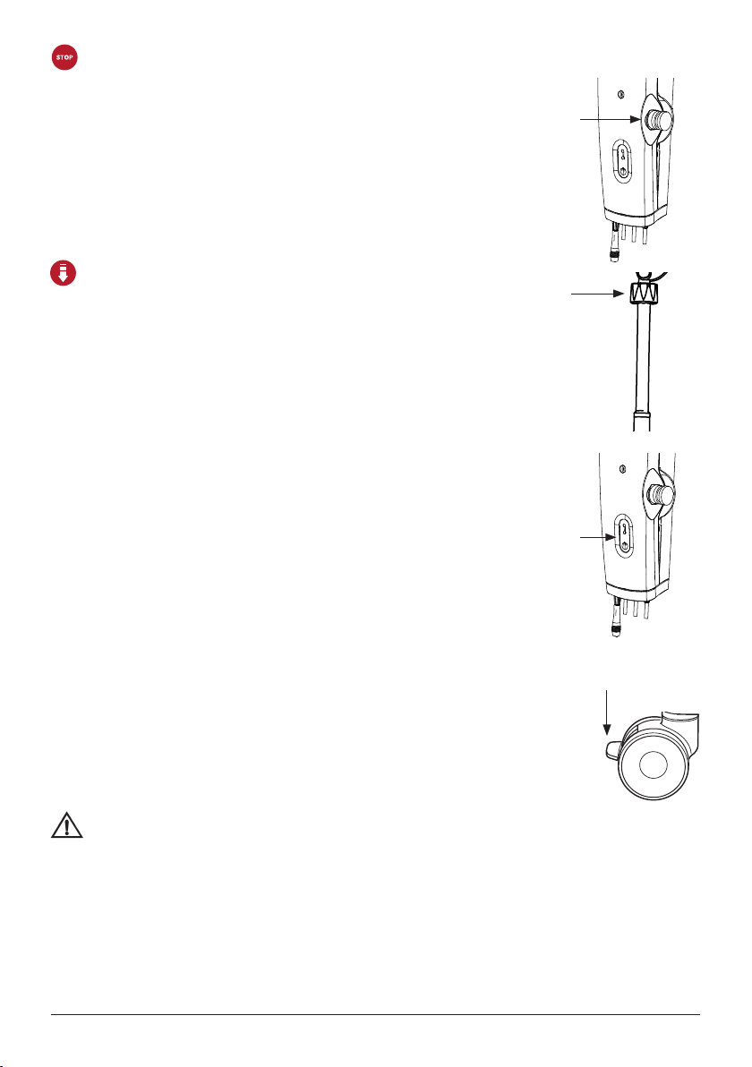
NOTE!
Before the lift is used for the first time, it must be charged for at least 4 hours.
Charge batteries regularly for maximum longevity. We recommend daily charging when
the lift is in daily use.
The emergency stop button must be pulled out during charging.
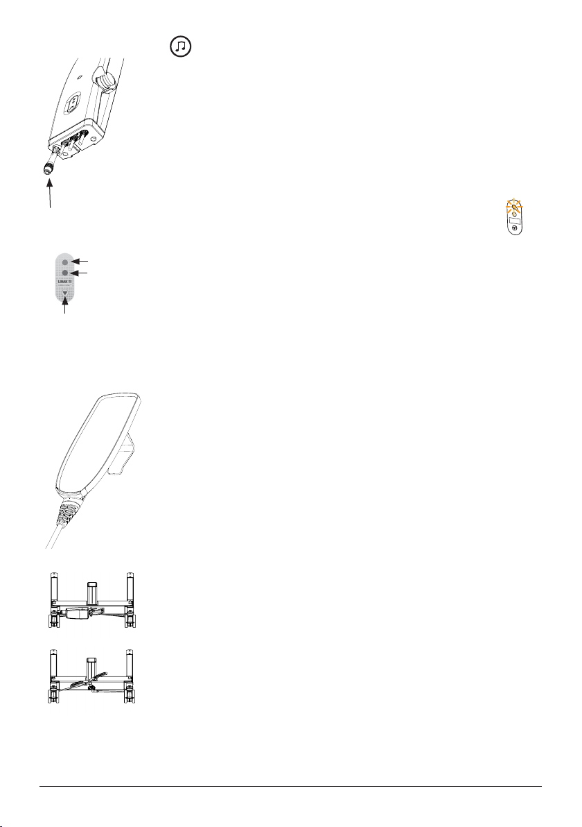
Handset
Raising/lowering the lift arm
Symbol indicate direction of travel.
Motion stops as soon as the button is released.
Base-width adjustment
Manual base-width adjustment (model EM)
Push down on the respective pedals at the back of
the lift to widen and narrow the base.
LED
indication of
charging
LED
indication
of handset
activation
Button for
electrical
emergency
lowering
Charger
6
Eva450EEL Eva600EEL
Eva450EML
REVISION HISTORY
REV.
DESCRIPTION
DATE
APPROVED
D
E
F
C
1
2
3
4
B
A
3
2
1
5
C
D
4
6
7
8
A
B
SCALE:1:10
DWG. NO.
REV.
NAME
DATE
DRAWN
APPROVED BY
SHEET 1 OF 1
WEIGHT:
COMMENTS:
STATUS:
TITLE
MATERIAL:
SIZE
Released
EVA EEL 450 base
90001288 02
g
2011-05-20
A3
Unless otherwise stated, general
tolerances according to ISO 2768-m
hc-jope
This drawing and any information or descriptive matter set out hereon are the confidential and copyright property of Handicare
and must not be disclosed, loaned, copied or used for manufacturing, tendering or any other purpose without their written permission.

Emergency stop
To activate emergency stop:
Depress the red emergency stop button on the control box.
Resetting:
Turn the button in the direction of the arrows until the button pops out.
To prevent battery discharge, we recommend that the emergency-stop button is pressed in
when the lift is not in use.
Emergency lowering
Manual emergency lowering:
For manual emergency lowering, turn the round plastic knob on the actuator clockwise.
Electrical emergency lowering:
For electrical emergency lowering, use the down button on the control box.
Brakes
Locking the wheels
Lock the rear wheels by pressing down on the brake pedals on both rear wheels with your
foot.
Wheels should not be locked during lifting, so that the lift can align itself with the patient’s
centre of gravity.
The only time the wheels should be locked is during lifting from the floor; otherwise, there is a
risk of the lift rolling and colliding with the patient’s head.
Locked wheels during lifting increase the risk of the lift tipping.
Unlocking the wheels
To release the wheel brakes, lift the brake pedals upwards with your foot.
7

Trouble shooting
If the lift or base-width adjustment cannot be activated, check the following:
- That the emergency stop button is not pressed in.
- That all cables are properly and securely connected. Pull out the contact and plug it in again firmly.
- That battery charging is not in progress.
- That the battery is charged.
If the lift is not working properly, contact your dealer.
If the lift makes unusual noises:
- Try to determine the source of the sound. Take the lift out of operation and contact your dealer.
8

9
MANUAL
B
C
D
1
2
A
3
2
1
4
B
A
5
6
C
3
SCALE:2:1
DWG. NO.
REV.
NAME
DATE
DRAWN
APPROVEDBY
SHEET1 OF 1
WEIGHT:
COMMENTS:
STATUS:
TITLE
MATERIAL:
SIZE
hc-mabr
-
-
- -
1023Carbon Steel Sheet (SS)
158.68g
2010-10-14
A4
Unlessotherwise stated,
generaltolerances
according to ISO 2768-m
Accessories
Slings:
For slings and other lifting accessories, please contact your local Vancare distributor.
VanderScale for weighing patients
Positioning aids:
Vanderclips
Ambulation Arm for gait training

Maintenance
The lift must undergo thorough inspection at least once per year. Inspection must be performed by authorized
personnel and in accordance with Vancare's service manual.
Repairs and maintenance may only be done by authorized personnel using original spare parts.
Spent batteries are to be left at the nearest recycling station.
Cleaning/disinfection
Clean the lift with warm water or rubbing alcohol and ensure that the caster wheels are free of dirt and hair. Do not
use cleaning agents containing phenol or chlorine, as this may damage the material.
Storage
If the lift is not to be used for some time or e.g., during transport, we recommend that the emergency stop button be
pressed in. Store the lift at a temperature above freezing point and not exceeding normal relative humidity (about 60%).
Service agreements
Vancare offers the possibility of service agreements for maintenance and regular testing of your mobile lift. Contact
your local Vancare representative.
10

11
Technical information
Lifting speed:
Batteries:
Charger:
Motor (mast):
Motor (base):
34 mm/s without load.
Two 12V, 2.9 Ah valve-regulated, sealed, lead accumulator (gel-type batteries)
Max. 400mA
DC 24 V, 10 A. IP X4. Operationtime: 10% at maximum continous operation of 2 minutes,
maximum 5.5 cycles per minute. Push: 10 000N.
24 V, 3 A, IP X4. Operationtime: 10% at maximum continous operation of 2 minutes,
maximum 5.5 cycles per minute. Push: 3000N.
Sound level:
Material:
With load: upwards: 74.7 dB(A) downwards: 52.6 dB(A).
Aluminum
Emergency lowering: Mechanical and electrical
Front 4”, 100 mm, back 4”, 100mmCastors:
Weight:
IP class:
Expected lifetime:
86 lbs, 39 kg
IP X4
10 years
Operating forces
buttons on handset: 4 N
The lift complies with the requirements of Council Directive 93/42/EEC of 14. June 1993 concerning medical devices.
The device is intended for indoor use.
Type B, according to the degree of protection against electric shock.

Dimensions VanGo 600
12
Column A measurement is in cm and weight is in kg.
Column B measurement is in inches and weight is in lbs.
A
8-18658-1A1 5A1A1
3-191A2A2 63-1A2 6
68-1A3 6A3A3 8-196
0-169B1B1 50-1B1 5
B2B2 54-1B2 54-174
B3B3 59-1B3 59-179
14CC
D 34 88
11,EE
F
133-192133-1G1G1G1
138-197138-1G2G2G2
G3G3 143-202143-2G3
H 55 2
BA
E
H
CD
F
G

Dimensions VanGo 600
13
Column A measurement is in cm and weight is in kg.
Column B measurement is in inches and weight is in lbs.
Mis turning diameter
Nis total weight of lift
Ois the weight of the heaviest component
Pis movement in forward direction
Ris referencemeasure 70 cm with max legspreading
Sis minimum distance from wall to slingbar at maximum
height (legs spread).
Tis minimum distance from wall to slingbar at maximum
reach (legs spread).
Uis minimum distance from wall to slingbar at minimum
height (legs spread).
A B
I 4444
17.73J 45
K
L
65-105 25.61-41.37
75-115 29.55-45.31
M 134134
N 39N 39
O 14,5 14,5
27QQ 27
4141SS
22T
U 45U 45
I
J
K
L
P
R
Q

Contact your local distributor if you have any questions about the product and its use. See www.vancare.com for a
complete list of distributors. Always make sure that you have the right version of the manual. The most recent editions
of manuals are available for downloading from our website, www.vancare.com
Manufactured for:
Vancare, Inc.
1515 First St
Aurora, NE 68818
1-800-694-4525
www.vancare.com

VANDER-LIFT9$1'(5/,)7,,9$1*2 Skills Observation Assessment
Staff Member Observed ___________________________________________ Date _____________
PROCEDURE - DID THE EMPLOYEE:
Have the required number of staff members present?
Select the correct size sling?
Inspect the sling and lift for damage and proper operation?
If DAMAGED, did the employee get another lift/sling and notify charge nurse?
Correctly position the sling so that the bottom center of the sling is at the tailbone?
Perform environment assessment and move objects that would impede operation of lift?
Move the lift into position with the hanger bar in the “H” position in front of the resident and
the base properly opened?
Properly use the locking casters (locking only on “ramped surfaces”)?
Lower the lift using the Pendant Switch?
Connect the sling loops to the hanger bar hooks? Use the same loops on each side?
Double check the sling attachment to the lift?
Lift the resident only as high as necessary?
Moving the lifter with a patient in the sling? (1 person pushes lift, while the other controls the
resident, using the “hand-loops”.)
Lower the lift until the resident is sitting on the chair or lying on the bed?
Remove the sling loops from the hanger bar hooks, and prevent the hanger bars from coming in
contact with the patient?
Back the lift away from the resident and remove the sling?
Make certain the resident is safe and comfortable before leaving?
KNOWLEDGE – CAN THE EMPLOYEE:
Identify lifting capabilities (maximum weight)?
Identify location and use of Emergency Stop Switch?
Identify location and use of Emergency Lowering?
Identify location and use of Auxiliary Up/Down Switch?
Identify Low Battery Indicator light?
Demonstrate how and when to recharge batteries?
Properly use the Scale attachment?
Identify sling parts: head support, shoulder loops, leg supports, leg loops, stabilizing
handles?
Demonstrate ability to adjust angle of recline to maintain hip precautions?
Demonstrate transfer of patient, using Vander-Lift, Vander-Lift II and VanGo, from bed to
to chair, chair to bed, and floor to bed?
Demonstrate proper understanding of how to clean the sling and lift?
Refer to Operator’s Manual for more detailed description of transfer technique.
Pass Fail
Observations __________________________________________________________________
_____________________________________________________________________________
Observer’s Name _______________________________________________________________
Observer’s Signature ____________________________________________________________
VANCARE, INC PHONE: (800)694-4525
1515 FIRST STREET FAX: (402)694-3994
AURORA, NE 68818 WEB: www.vancare.com
Table of contents
Other Vancare Medical Equipment manuals