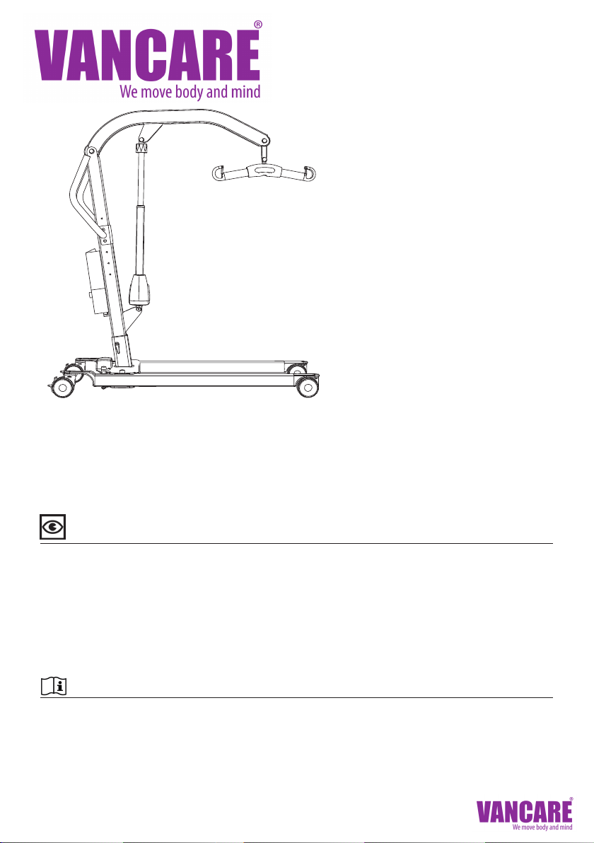
1. Boom
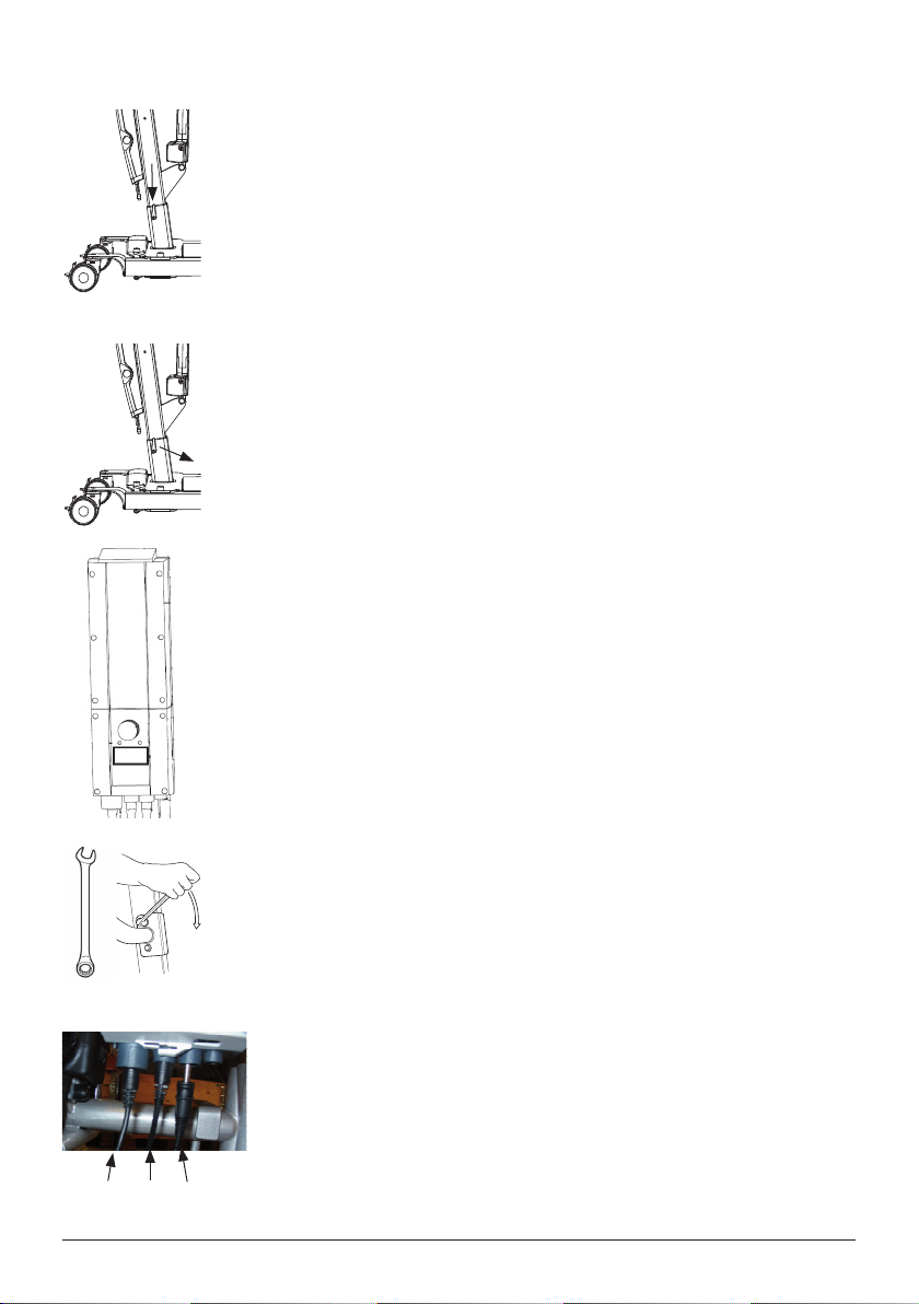
2. Mast
3. Handlebar
4. Battery pack
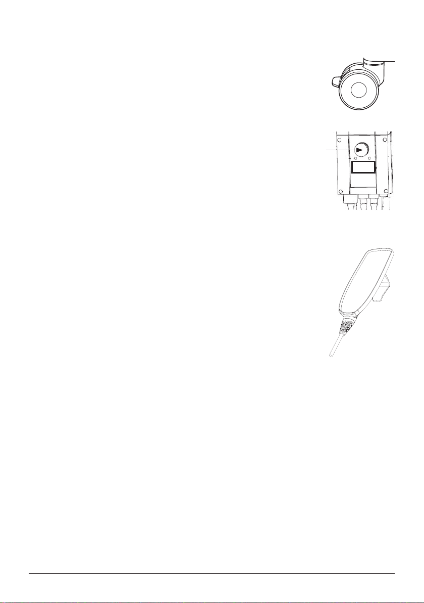
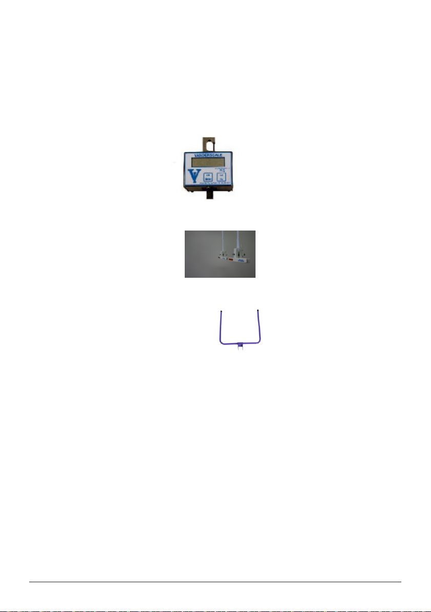
5. Emergency stop
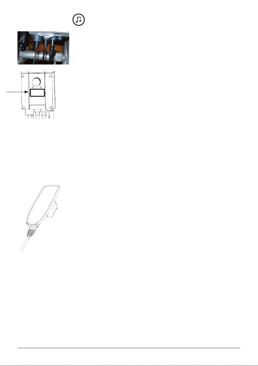
6. Control box
7. Motor for base-width adjustment
8. Rear castors with brakes
9. SlingBar with safety latch
10. Front castors
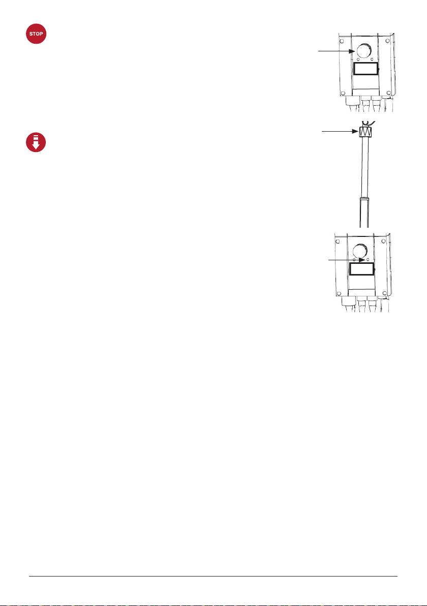
11. Emergency lowering
12. Motor/actuator for boom
13. Mast height adjustment
Max. load: 205 kg / 450Ibs
Mobile lift Eva450EE has been developed to meet most lifting needs in combination with the right accessories. It is a lift
that can lift patients in a seated or supine position.The Eva450EE is made largely of aluminium, which makes it relatively
light, considering the weight it can lift.
Handicare’s SystemRoMedic product series includes a range of lifts, slings and other accessories. SystemRoMedic
adopts a holistic approach to patient transfers and is organized in four categories: transfer, positioning, support and
lifting.
Manual nr: 00789En Ver. 2 110203
Visual inspection
Inspect lift functions regularly. Check to ensure that material is free from damage.
Before use:
Ensure that the product is correctly assembled.
Check slingbar connection and safety latch function.
Check lift and base-width movement.
Check to ensure that the actuator is correctly installed.
Always read the manuals for all assistive devices used during a transfer.
Keep the manual where it is accessible to users of the product.
The lift may only be used by persons who have received instruction in the operation of the lift.
Functional inspection
Always read the manual
Manual - English
1
2
3
4
5
6
7
8
9
10
11
12
13
VanGo VG400/VG450 has been developed to meet most lifting needs in combination with the right
accessories. It is a lift that can lift patients in a seated or supine position. The VanGo is made largely
of aluminum, which makes it relatively light, considering the weight it can lift.