Vanderbilt Vanderbilt 2015
CFMW2035 QIG 28.07.2015 page 2
CFMW2035 – Quick installation guide
About this document
This guide outlines the most important information regarding the installation of the camera. For instructions
regarding the configuration and further information, please refer to the configuration manual on CD.
Package Contents
•One Network Fixed Dome Camera
•One printed quick installation guide
•One plug for conduit holes
•One torx key (T10)
•Four tapping screws
•Four screw anchors
•Two mounting templates
•One CD containing the IP Finder, user
manual and quick installation guide
Target Group
This installation guide is only intended for use
by installers who have an adequate working
knowledge of video surveillance systems.
The installation should be made by a qualified
service person and should conform to all local
codes.
Safety
General safety precautions
•Read the general safety precautions before
installing the device.
•Use the device only for its intended use.
•Keep this document for reference.
•Always keepthis documenttogetherwiththe
product.
•Please also take into account any
additional country-specific, local laws,
safetystandards or regulations
concerning installation, operation and
disposal of the product.
Liability claim
•Do not connect the device to the 230 V
supply network if it is damaged or any parts
are missing.
•Use only spare parts and accessories
that have been approved by the
manufacturer.
Setup
Damage due to unsuitable mounting location
•The environmental conditions
recommended by the manufacturer must be
observed. See Technical Data.
•Do not operate the device close to sources
of powerful electromagnetic radiation.
•Do not operate the device in dusty places.
•Protect the device against moisture.
Danger of electrical shock/fire hazard/damage
to the device due to incorrect connection
•Connect the device only to power sources
with the specified voltage.Voltage supply
requirements can be found on the rating label
of the device.
•Connect the device only to a limited power
source.
•Connect the equipment to AC24V UL Listed
Class 2 Power Supply or PoE/PoE+.
Power Supply
•Ensure that the AC power supplyis stable
and within the rated voltage ofthe unit. Use
an uninterrupted power supply (UPS) to
ensure a continuous function of the unit in the
event of power dips on theAC mains supply.
Service and maintenance
The camera is maintenance-free. Small
amounts of dirt or dust can be cleaned from the
camera body using a clean soft cloth
Danger of electrical shock during maintenance
•Donot attempt to serviceormodifythisdevice
yourself.
Refer this work to qualified service personnel.
Description of equipment
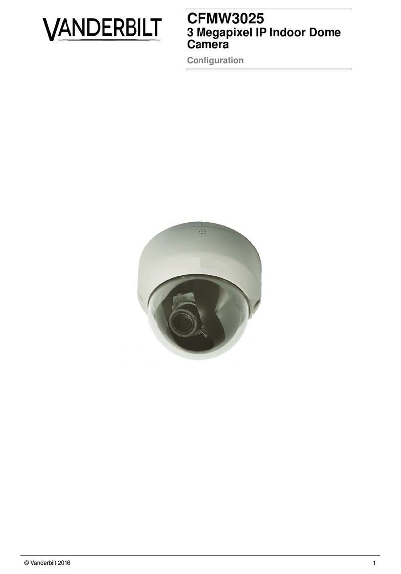
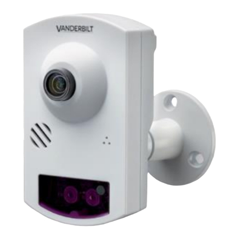
CFMW2035 is a 2MP Xaria IP Fixed Dome
camera with dual codecs for multiple video
surveillance applications. Refer to the qualified
technicians for multiple installation methods on
a variety of environments with required optional
tools
Details of ordering
2MP IP Fixed
Dome, Varifocal
Installation
Step 1: Connecting the cables
(a) Using the side conduit hole
1. Connect the Internet cable to the Ethernet connector
(17) via PoE switch for network connectivity and
power input.
2. Or connect the power supply cable to the AC24V
power connector (16).
Note:
DO NOT connect 2 power options (AC24V/PoE)
simultaneously.
3. Connect the control input/output to the terminals I/O
Connectors (15).
4. Clean the thread grooves in the bottom conduit hole
and install the plug firmly into the bottom conduit
hole to prevent moisture from getting inside the
casing.
(b) Using the bottom conduit hole
Similar to the procedure of side conduit hole, connect the
required cables to the respective connectors via bottom
conduit hole and install the plug firmly into the side
conduit hole at the final stage to complete the procedure.
Step 2: Mounting the camera
Flush Mount:
1. Disassemble the camera housing (7), lens base (2),
and bottom case (1) apart
2. Place the lens base within the desired ceiling
location and extend the 2 locking arms by turning
the 2 black-colored screws clockwise.
3. Tighten the 2 black-colored screws sufficiently to
compress the locking arms to adjust and fix to the
flush mount area
4. Mount the camera housing on the lens base, both of
which have a red dot respectively for aligning
identification.
5. Use the torx key supplied to tighten the 3 camera
housing screws (6) for mounting completion.
Surface Mount:
1. Disassemble the camera housing (7), lens base (2),
and bottom case (1) apart
2. Place the mounting template on the mounting
surface and mark the holes as indicating places.
3. Drill the holes on the marked places.
4. Insert the screw anchors supplied into the holes.
5. Fasten the bottom case (1) with the screws provided
to the mounting surface.
6. Allign the red dot of lens base with the red dot of
bottom case and fix the 3 torx screws by torx key
supplied.
Step 3: Adjusting the camera
position
1. Lift up the inner liner (5).
2. Rotate 3D assembly in the lens base (maximum
354°), pan horizontally the lens base (maximum
354°) and adjust the lens tiltly into the desired
direction of image.
3. Cover back the inner liner on the lens.
Caution
Do not turn the lens more than 354° as this may cause
internal cables to disconnect or break.
Step 4: Attaching the dome to the
unit
Note
Use a soft lint-free cloth to wipe the dome cover clean
and remove fingerprints.
1. Clean the joint surfaces of the unit.
2. Place the camera housing with dome cover on the
unit.
3. Match the screws on the camera housing (7) to the
screw holes (3 locations) on the lens base (2).
4. Hold the camera housing to maintain the matched
positions, and tighten the three screws (6) with the
torx key to lock the camera housing to the lens
base.
Start-up Procedure
1. Switch on the power supply.
2. Connectthenetwork cable to theRJ-45
network port.
3. Open IE browser and access the IP
camera by the following default settings.
IP address: 192.168.0.10
User: admin
Password: admin
4. Set the parameters and back up the file.
Note: Read out the camera parameters and
save this file before making any changes. During
this process, the screen image may be disturbed.
Set the parameters and back up the file. Detailed
information on parameter settings can be found
in the user manual on the CD.
Information
This equipment generates and radiates radio
frequency energy and, if not installed and used
in accordance with the instructions, may cause
harmful interference to radio communications.
You are cautioned that any changes or
modifications not expressly approved in this
manual could void your authority to operate this
equipment.
