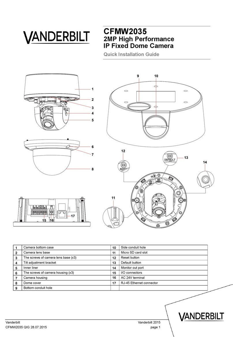
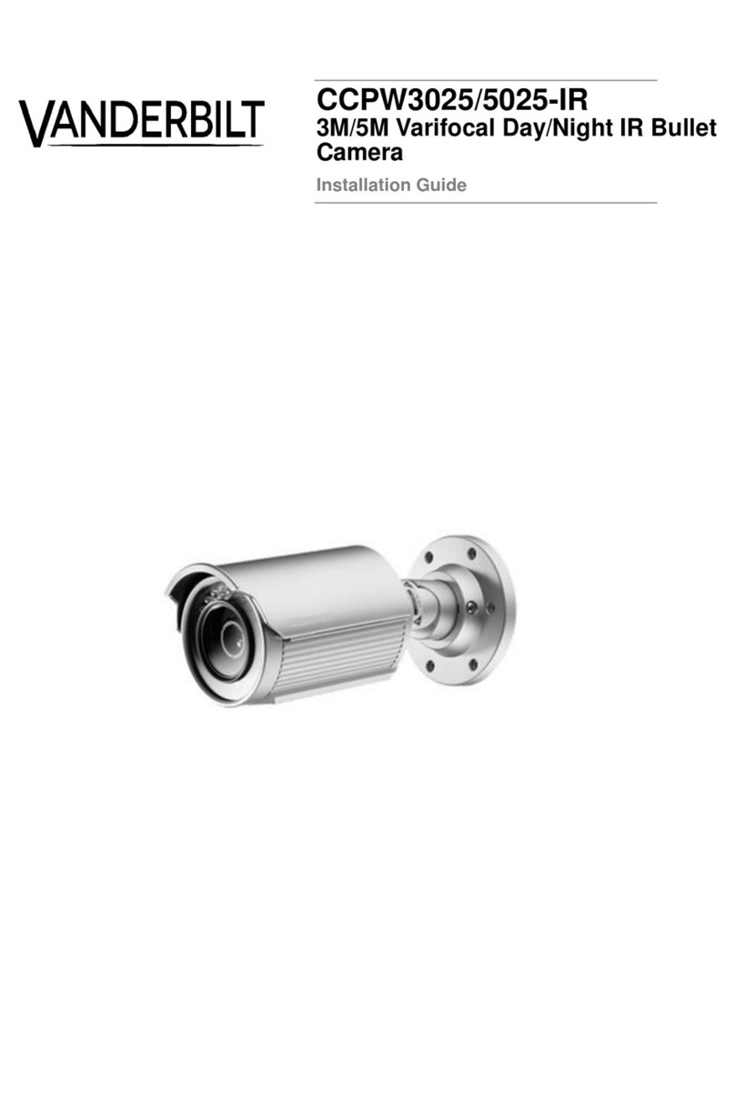
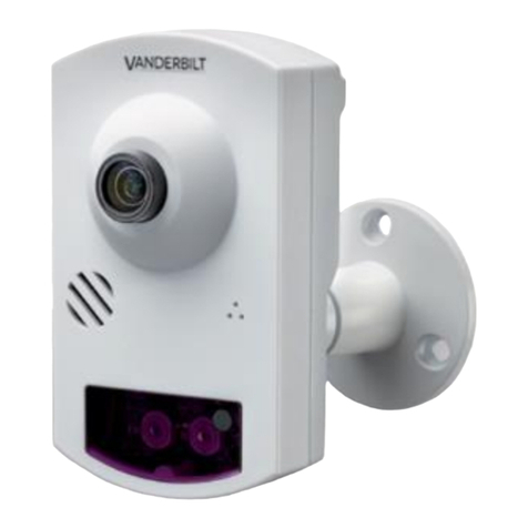
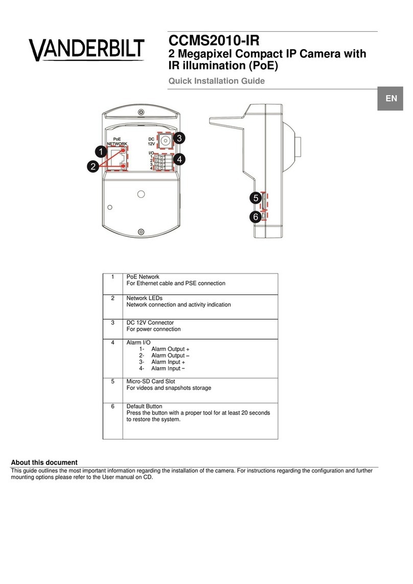
Vanderbilt CCID1445-DN28 User manual

16
15
13
12
18
17
14
9
10
11
5
6
8
7
Audio GND
Unit: mm
1
4
3
2
COM
Alarm 1
Alarm 2
Alarm 3
N.O.
Alarm 4
GND
N.C.
Audio OUT
Audio IN
220164
Ø 134
CCID1445-DN28, -DN36
¼” IP High-Speed Dome Camera, Day/Night
¼" IP High-Speed Dome Kamera, Tag/Nacht
Installation Instruction / Installationsanleitung
About this document
This guide outlines the most important information regarding the
installation of the camera. For instructions regarding the
configuration and further mounting options please refer to the
configuration manual on CD.
Zu diesem Dokument
In dieser Installationsanleitung finden Sie die Anweisungen zur
Installation der Kamera. Anweisungen zur Konfiguration und weitere
Montagevarianten finden Sie im Konfigurationshandbuch auf der
CD.
English
1
Camera base
2
Hook
3
Safety wire
4
Dome module
5
Mounting bracket
6
MicroSD card slot
7
Terminal for audio in/out & alarm in/out
8
Video output
9
Ethernet connector
10
Power terminal
11
System LED
12
Reset button
13
Default button
14
Video cable
15
Notch
16
Label with arrows
17
Not applicable
18
Lens
Deutsch
1
Kameraunterteil
2
Haken
3
Sicherungsdraht
4
Dome-Modul
5
Befestigungswinkel
6
Steckplatz für MicroSD-Karte
7
Audio- und Alarmein- und -ausgänge
8
Videoausgang
9
Ethernet-Anschluss
10
Anschluss Spannungsversorgung
11
System-LED
12
Reset-Taste
13
Default-Taste
14
Videokabel
15
Markierung
16
Aufkleber mit Pfeilen
17
Nicht anwendbar
18
Objektiv

CCID1445, IP High-Speed Dome Camera, D/N
© Vanderbilt 2016
2
Package contents
Camera base
Dome module
Template
3 anchors
3 screws
Video cable
2 GB MicroSD card (in box)
Installation instruction
Utilities CD (including software and documentation)
Target readers
This installation instruction is only intended for use by
installers who have an adequate working knowledge of video
systems!
Installation must be performed by qualified service personnel
in accordance with all local codes.
Safety
General safety precautions
Read the general safety precautions before
installing/configuring/operating the device.
Keep this document for reference.
Always pass this document on together with the product.
Please take into account any additional country-specific,
local laws, safety standards or regulations concerning
installation, operation and disposal of the product.
Ensure that the safety wire (located in the dome base) is
engaged.
Use only spare parts and accessories that have been
approved by the manufacturer.
Transport
Keep the packaging material for future transportation.
Do not expose the device to mechanical vibrations or
shocks.
Installation
Refer to a qualified electrician for installation.
The environmental conditions recommended by the
manufacturer must be observed. See "Technical data".
Do not operate the device close to sources of powerful
electromagnetic radiation.
The device should only be used for indoor applications.
The mounting surface must be solid and non-
combustible.
Danger of electrical shock/fire hazard/damage to the
device due to incorrect connection
Connect the device only to a power source that complies
with SELV requirements and with the Limited Power
Source requirements to EN 60950-1.
Connect the equipment to 24 V AC UL listed Class 2
Power Supply or PoE+.
Service and maintenance
Do not attempt to service or modify this device yourself.
Refer this work to qualified service personnel.
Do not use liquid cleaners or sprays that contain alcohol,
spirit or ammonia.
Details for ordering
Type
CCID1445-DN28
Part no.
V54561-C32-A1
Designation
1/4" IP Speed Dome, Colour, 28 x
Optical Zoom, 24 V AC, PoE+
Type
CCID1445-DN36
Part no.
V54561-C33-A1
Designation
1/4" IP Speed Dome, D/N, 36 x
Optical Zoom, 24 V AC, PoE+
Installation
Step 1: Mounting
1. Mark the mounting holes for the dome camera using the
drilling template.
2. Drill the mounting holes and insert the wall plugs.
3. If necessary, cut a space for the supply cables at the
mounting location.
4. If required, remove the knockout for cable entry.
5. Pass the cables into the housing.
6. Attach the unit to the mounting surface using the screws
included in the delivery.
7. Connect the support wire (3) to the hook (2) of the dome
base (1).
Step 2: Connection
Alarm input
Connect the control input to the terminals GND and AL IN (7).
IP interface
Connect the IP cable for configuration and operation via
Ethernet to the RJ45 connector (9).
BNC connector
If required, connect the BNC extension cable (14) to the BNC
connector (8).
Power supply
Select one of the following options:
24 V AC:
Connect the 24 V AC cables to the terminals 24VAC.
PoE:
Connect the network cable to the RJ45 terminal (9) using
a PoE+ compatible hub or switch.
Step 3: Mounting the camera module
To lock the dome module (4) to the camera base (1), line up
the notch (15) to the right arrow on the label (16), then turn
the dome module to the right with both hands until the notch
lines up to left arrow.
Start-up procedure
When powered up, the camera will perform a brief routine
during which it checks its function and will then go to its start
position.
Install the remote software onto your PC, following the
description in the "Readme" file on the CD.
Access the IP camera.
Default settings:
IP address: 192.168.0.10
User: admin
Password: admin
Set the parameters and back up the file.
Detailed information on parameter setting can be found in the
operator manual on CD.
Firmware check/update
If you require further information, please contact our support
team:
www.service.vanderbiltindustries.com
Technical data
Image sensor
1/4“ Ex-View CCD
Horizontal
resolution
D/N: 530 TV lines
Col.: 480 TV lines
Resolution
MJPEG: D1 (720 x 576) / VGA
(640 x 480) / QVGA
(320 X 240): 25 ips (PAL)
MPEG-4: D1 (720 x 576) / VGA
(640 x 480) / QVGA
(320 X 240): 25 ips (PAL)
H.264: D1 (720 x 576) / VGA (640 x
480) / QVGA
(320 X 240): 25 ips (PAL)
Image compression
MJPEG / MPEG-4 /
H.264 (triple encoding)
Sensitivity
DN28: Color 1.0 lux (F1.6; 1/50 s)
B/W 0.01 lux (F1.4; 1/3 s)
DN36: Color 1.4 lux (F1.6; 1/50 s)
B/W 0.01 lux (F1.4; 1/3 s)
Storage medium
MicroSD card, up to 32 GB
Network connection
10BASE-T / 100BASE-TX
Internet protocol
TCP/IP, UDP, HTTP, HTTPs,
SMTP, SNMP, DNS, DHCP, NTP,
ARP, ICMP, FTPc, FTPs, DDNS,
RTSP (RTP, RTCP),
IGMP v3, UPnP,
CIFS, NFS, IEC802.1x, ONVIF
Web browser
Internet Explorer 6.0 (Service Pack
2 or above) / Safari / Mozilla
FireFox
Power supply
24 V AC ± 10 %, 50 Hz; PoE+
Power consumption
25 VA
Environmental
operating
temperature
0 –50 °C
(-30 to +50 °C with suitable
weatherproof housing)
Storage
temperature
-20 to +60 °C
Weight
1.85 kg
Dimensions (Ø x H)
134.0 x 220.0 mm
Disposal
All electrical and electronic products should be
disposed of separately from the municipal
waste stream via designated collection facilities
appointed by the government or the local
authorities.

CCID1445, IP High-Speed Dome Camera, T/N
© Vanderbilt 2016
3
Lieferumfang
Kameraunterteil
Dome-Modul
Bohrschablone
3 x Dübel
3 x Schrauben
Videokabel
MikroSD-Karte 2 GB (mit Box)
Installationsanleitung
CD mit Dienstprogrammen (einschl. Software und
Dokumentation)
Zielgruppe
Diese Anleitung ist nur für Fachpersonal vorgesehen, das mit
Videotechnik ausreichend vertraut ist!
Die Installation darf nur von qualifiziertem Servicepersonal
gemäß den geltenden Vorschriften durchgeführt werden.
Sicherheitshinweise
Allgemeine Sicherheitshinweise
Lesen Sie vor der Installation / Konfiguration / Inbetrieb-
nahme des Gerätes die allgemeinen Sicherheitshinweise.
Bewahren Sie dieses Dokument zum Nachschlagen auf.
Geben Sie dieses Dokument bei der Weitergabe des
Produktes mit.
Beachten Sie zusätzlich die landesspezifischen und
ortsüblichen Gesetze, Richtlinien und Normen für die
Installation, den Betrieb und die Entsorgung des
Produktes.
Stellen Sie sicher, dass der Sicherungsdraht (im Dome-
Sockel) eingehakt ist.
Verwenden Sie nur vom Hersteller genehmigte Ersatz-
und Zubehörteile.
Transport
Bewahren Sie die Verpackung für den Weitertransport
auf.
Setzen Sie das Gerät keinen mechanischen
Erschütterungen oder Stößen aus.
Installation
Lassen Sie die Installation nur von einer Elektrofachkraft
durchführen.
Halten Sie die vom Hersteller empfohlenen Umgebungs-
bedingungen ein. Siehe Kapitel "Technische Daten".
Betreiben Sie das Gerät nicht in der Nähe einer stark
elektromagnetischen Strahlungsquelle.
Verwenden Sie das Gerät nur im Innenbereich.
Montieren Sie das Gerät nur auf festen und nicht
brennbaren Oberflächen.
Personenschaden/Brandgefahr/Geräteschaden durch
falschen Anschluss an die Spannungsversorgung
Betreiben Sie das Gerät nur an einem Netzgerät/
Spannungsversorgung, das den SELV-Anforderungen
und den Anforderungen "Stromquelle begrenzter
Leistung" (Limited Power Source) nach EN60950-1
entspricht.
Schließen Sie das Gerät an ein geeignetes 24-V AC-
Netzgerät (UL Klasse 2) oder PoE+ an.
Wartung und Instandhaltung
Lassen Sie Wartungsarbeiten und Änderungen an
diesem Gerät nur von Fachpersonal durchführen
Verwenden Sie keine Flüssigreiniger oder Sprays, die
Alkohol, Spiritus oder Ammoniak enthalten.
Bestellangaben
Typ
CCID1445-DN28
Bestellnummer
V54561-C32-A1
Bezeichnung
1/4" IP Speed Dome Farbe, 28 x
optischer Zoom, 24 V AC, PoE+
Typ
CCID1445-DN36
Bestellnummer
V54561-C33-A1
Bezeichnung
1/4" IP Speed Dome, T/N, 36 x
optischer Zoom, 24 V AC, PoE+
Installation
Schritt 1: Montage
8. Befestigen Sie die Bohrschablone an der
Montageposition und markieren Sie die Bohrungen.
9. Bohren Sie die Löcher und setzen Sie die Dübel ein.
10. Bereiten Sie an der Montageposition ggf. eine Öffnung
für die Versorgungskabel vor.
11. Entfernen Sie bei Bedarf den vorbereiteten Verschluss
für die Kabeleinführung.
12. Führen Sie die Kabel in das Gehäuse ein.
13. Befestigen Sie die Einheit mit den beigefügten
Schrauben.
14. Hängen Sie den Sicherungsdraht (3) in den Haken (2)
am Dome-Sockel (1) ein.
Schritt 2: Anschließen
Alarmeingang
Den Steuereingang mit den Anschlüssen GND und AL IN (7)
verbinden.
IP-Schnittstelle
Schließen Sie das IP-Kabel zur Parametrierung und
Bedienung über Ethernet am RJ45-Anschluss (9) an.
BNC-Anschluss
Schließen Sie bei Bedarf das BNC-Verlängerungskabel (14)
an den BNC-Anschluss (8) an.
Stromversorgung
Wählen Sie eine der folgenden Optionen:
24 V AC:
Schließen Sie die 24 V AC Leitungen an die Klemmen
24VAC an.
PoE:
Verbinden Sie das Netzwerkkabel mit einem
PoE+ fähigen Hub oder Switch am RJ45-Anschluss (9).
Schritt 3: Kameramodul montieren
Um das Dome-Modul (4) am Kameraunterteil (1) zu
arretieren, richten Sie die Arretierungsmarke (15) mit dem
rechten Pfeil auf dem Aufkleber (16) aus; drehen Sie das
Dome-Modul mit beiden Händen nach rechts, bis sich die
Arretierungsmarke über dem linken Pfeil befindet.
Inbetriebnahme
Nach dem Einschalten der Spannungsversorgung führt die
Kamera eine kurze Routine mit Funktionsprüfung durch und
fährt dann in die Startposition.
Installieren Sie die Remote-Software auf Ihrem PC wie in der
Datei “Bitte lesen” auf der CD beschrieben.
Greifen Sie auf die IP-Kamera zu.
Standardvorgaben:
IP-Adresse: 192.168.0.10
Benutzer: admin
Kennwort: admin
Stellen Sie die Parameter ein und sichern Sie die Datei.
Ausführlichere Informationen finden Sie in der
Bedienungsanleitung auf der CD.
FW-Prüfung/Aktualisierung
Kontaktieren Sie für weitere Informationen unseren Support:
www.service.vanderbiltindustries.com
Technische Daten
Bildsensor
1/4“ Ex-View CCD
Horizontale
Auflösung
T/N: 530 Zeilen
Farbe: 480 Zeilen
Auflösung
MJPEG: D1 (720 x 576) / VGA
(640 x 480) / QVGA
(320 X 240): 25 ips (PAL)
MPEG-4: D1 (720 x 576) / VGA
(640 x 480) / QVGA
(320 X 240): 25 ips (PAL)
H.264: D1 (720 x 576) / VGA (640 x
480) / QVGA
(320 X 240): 25 ips (PAL)
Bildkompression
MJPEG / MPEG-4 /
H.264 (Triple Encoding)
Empfindlichkeit
DN28: Farbe 1,0 lux (F1,6; 1/50 s)
S/W 0,01 lux (F1,4; 1/3 s)
DN36: Farbe 1,4 lux (F1,6; 1/50 s)
S/W 0,01 lux (F1,4; 1/3 s)
Speichermedium
MikroSD-Karte, bis 32 GB
Netzwerkanschluss
10 BASE-T / 100 BASE-TX
Internetprotokoll
TCP/IP, UDP, HTTP, HTTPs,
SMTP, SNMP, DNS, DHCP, NTP,
ARP, ICMP, FTPc, FTPs, DDNS,
RTSP (RTP, RTCP),
IGMP v3, UPnP, CIFS, NFS,
IEC802.1x, ONVIF
Web-Browser
Internet Explorer 6.0 (Service Pack
2 oder höher) / Safari / Mozilla
FireFox
Stromversorgung
24 V AC ± 10 %, 50 Hz; PoE+
Leistungsaufnahme
25 VA
Betriebsumge-
bungstemperatur
0 –50 °C
(-30 bis +50 °C mit geeignetem
Wetterschutzgehäuse)
Lagertemperatur
-20 bis +60 °C
Gewicht
1,85 kg
Abmessungen
(Ø x H)
134,0 x 220,0 mm
Entsorgung
Elektrische und elektronische Geräte dürfen
nicht im Hausmüll entsorgt werden, sondern
sind an den von den Kommunen dafür
eingerichteten Sammelstellen abzugeben.
CCID1445, IP High-Speed Dome Camera, D/N
Issued by Vanderbilt
Clonshaugh Business and Technology Park
Clonshaugh
Dublin 17
Ireland
www.vanderbiltindustries.com
© Vanderbilt 2016
Data and design subject to change without notice
Supply subject to availability
Document no.: C-300614
Document version: 2.0
Edition:3/23/2016
This manual suits for next models
3
Table of contents
Languages:
Other Vanderbilt Security Camera manuals

Vanderbilt
Vanderbilt Eventys CCDM2010-OIRD User manual

Vanderbilt
Vanderbilt CCPW3025-IR User manual

Vanderbilt
Vanderbilt CFMW2035 User manual

Vanderbilt
Vanderbilt CCMS2010-IR User manual

Vanderbilt
Vanderbilt CCPW3025-IR User manual

Vanderbilt
Vanderbilt CCMD2010-OIR User manual

Vanderbilt
Vanderbilt CCPS1317-LPOIR Quick guide

Vanderbilt
Vanderbilt CFMW3025 Instruction sheet

Vanderbilt
Vanderbilt CCMS2010-IR/IRW User manual