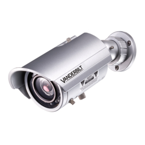
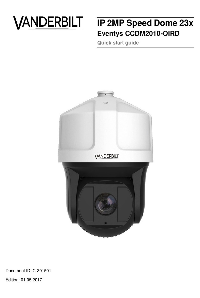
Vanderbilt CCPW3025-IR User manual

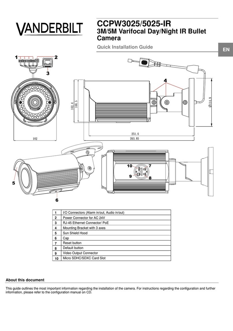
CCPW3025/5025-IR
3M/5M Varifocal Day/Night IR Bullet
Camera
Installation Guide

© Vanderbilt 2016
2
Data and design subject to change without notice. / Supply subject to availability.
Liefermöglichkeiten und technische Änderungen vorbehalten.
© 2016 Copyright by Vanderbilt
We reserve all rights in this document and in the subject thereof. By acceptance of the document the recipient acknowledges these rights
and undertakes neither to publish the document nor the subject thereof in full or in part, nor to make them available to any third party without
our prior express written authorization, nor to use it for any purpose other than for which it was delivered to him.
Wir behalten uns alle Rechte an diesem Dokument und an dem in ihm dargestellten Gegenstand vor. Der Empfänger erkennt diese Rechte
an und wird dieses Dokument nicht ohne unsere vorgängige schriftliche Ermächtigung ganz oder teilweise Dritten zugänglich machen oder
außerhalb des Zweckes verwenden, zu dem es ihm übergeben worden ist.

© Vanderbilt 2016
3
Contents
1About this document..............................................................................5
2Safety .......................................................................................................6
2.1 Target Group.............................................................................................6
2.2 General safety precautions.......................................................................6
2.3 Service and maintenance .........................................................................6
2.4 Meaning of the written warning notices.....................................................7
2.5 Meaning of the hazard symbols................................................................7
3EU-directives...........................................................................................8
4Technical Data.........................................................................................9
5Details for ordering...............................................................................13
6Package contents..................................................................................14
7Description of equipment.....................................................................15
7.1 I/O connector definition...........................................................................16
7.2 Internal PIN definition..............................................................................16
8Installation .............................................................................................17
8.1 Mounting the camera ..............................................................................17
8.2 Connecting the wires...............................................................................19
8.3 Adjusting the camera position.................................................................20
8.4 Adjusting the sun shield hood.................................................................21
8.5 SD memory card .....................................................................................21
8.6 Concept of the network camera..............................................................22
8.7 Setting network camera environment .....................................................22
8.8 Connecting the camera and personal computer via network .................23
8.9 Using the camera search application "Webcam IP Manager"..................25
8.10 Login dialog.............................................................................................27
8.11 Viewing and listening ..............................................................................28
8.12 Resolution ...............................................................................................31
9Configuration.........................................................................................32
9.1 Compression...........................................................................................32
9.2 Networksettings......................................................................................33
9.2.1 Basic .......................................................................................................33
9.2.2 DDNS Settings........................................................................................35
9.2.3 FTP Server..............................................................................................35
9.2.4 RTSP.......................................................................................................35
9.2.5 HTTPS.....................................................................................................36
9.2.6 IEEE802.1X.............................................................................................36
9.2.7 SNMP......................................................................................................37
9.2.8 3GPP.......................................................................................................37
9.3 Imageparameter.....................................................................................38
9.3.1 Basic camera settings.............................................................................38
9.3.2 Camera mask zone settings....................................................................41
9.3.3 Camera cropping settings.......................................................................42
9.3.4 Camera OSD settings .............................................................................43
9.4
Alarm
.......................................................................................................44
9.4.1 Alarm.......................................................................................................44
9.4.2 Audio event upload .................................................................................48
9.4.3 Alarm server............................................................................................49
9.5
Record
.....................................................................................................50
9.5.1 Basic .......................................................................................................50
9.5.2 FTP Recording........................................................................................51
© Vanderbilt 2016
4
9.5.3 SD recording ...........................................................................................53
9.5.4 Email recording .......................................................................................54
9.5.5 NAS recording.........................................................................................58
9.6 Audio.......................................................................................................60
9.7 Date / Time..............................................................................................61
9.8 Accessprotection....................................................................................63
9.8.1 Administrator...........................................................................................63
9.8.2 User list ...................................................................................................64
9.9 Firewall....................................................................................................65
9.9.1 IP Address filter.......................................................................................65
9.9.2 Forbidden ports.......................................................................................66
9.9.3 Forbidden protocols ................................................................................66
9.10 System ....................................................................................................67
9.10.1 Settings ...................................................................................................67
9.10.2 Update.....................................................................................................68
9.10.3 Configuration...........................................................................................69
9.10.4 Back Focus..............................................................................................70
9.10.5 Temperature............................................................................................71
9.10.6 Calibration...............................................................................................71
9.10.7 Self-Testing.............................................................................................72
9.11 Log ..........................................................................................................72
9.12 Notice......................................................................................................73
10 Utility program application...................................................................74
10.1 NAS player setup ....................................................................................74
10.2 Audio recording setup.............................................................................74
10.3 Firmware update setup for multiple cameras..........................................75
11 Maintenance ..........................................................................................76
12 Disposal .................................................................................................77

About this document
© Vanderbilt 2016
5
1 About this document
This document contains information about installing and configuring the device.
Trademarks
All product or company names mentioned in this document are trademarks or
regis-
tered trademarks of their respective owners and are used only for
purposes of iden-
tification or description.
Contacting us
If you have questions or suggestions regarding the product or this
documentation,
please contact our Technical Competence Center.
Internet: www.service.vanderbiltindustries.com
Trainings
Vanderbilt provides training courses for all products.
Orientation
[-> 3]
Cross reference
Save
Button
<Ctrl>
Key
Tips and information

Safety
© Vanderbilt 2016
6
2 Safety
2.1 Target Group
Target group
Qualification
Activity
Condition of
the
product
Installer
Technicaltrain-
ing
for electrical
installations.
Installs the
product,
Indi-
vidual
compo-
nents of
the
product or
re-
placement
parts.
Components of
the product are
not yet installed
or
need to be
replaced or
modified.
Target group
Qualification
Activity
Condition of
the
product
Operational
startup
personnel
Technicaltrain-
ing
for electrical
installations.
Training on the
product is
rec-
ommended.
Puts the product
into operation for
the first time, or
changes the
ex-
isting
configura-
tion.
The product is
installed but not
yet configured,
or
the existing
configuration is
to be changed.
2.2 General safety precautions
Read the general safety precautions before installing and configuring the device.
Use the device only for its intended use. See section description of equipment'.
Keep this document for reference purposes.
This document must always accompany the product.
Please take into account any additional country-specific, local laws, safety
standards or regulations concerning installation, operation and disposal of the
product.
Please read the documentation to be found on the accompanying CD.
Liability claim
Do not connect the device to the 230 V supply network if it is damaged or any
parts are missing.
Do not make any changes or modifications to the device unless they have been
approved by the manufacturer.
Use only spare parts and accessories that have been approved by the manu-
facturer.
2.3 Service and maintenance
Danger of electrical shock during maintenance

Safety
© Vanderbilt 2016
7
Do not attempt to service or modify this device yourself. Refer this work to
quali-
fied service personnel.
2.4 Meaning of the written warning notices
CAUTION Risk of minor to medium injuries or damage to property
IMPORTANT Malfunctioning may result
2.5 Meaning of the hazard symbols
Warning of a hazard

EU-directives
© Vanderbilt 2016
8
3 EU-directives
This product complies with the requirements of the following European
directives.
The EU declaration of conformity is available to the responsible agencies at:
Vanderbilt
Clonshaugh Business and Technology Park
Clonshaugh
Dublin 17
Ireland
www.vanderbiltindustries.com
European Directive2004/108/EC „Electromagnetic Compatibility”
Compliance with
the European Directive 2004/108/EC has been proven by
testing according to the
following standards:
Emitted interference:
EN 61000-6-3
Interference resistance:
EN 50130-4
European Directive 2006/95/EEC „Low-Voltage Directive”
Compliance with the European Directive 2006/95/EEC has been proven by testing
according to the following standards:
Safety:
EN 60950-1

Technical Data
© Vanderbilt 2016
9
4 Technical Data
Model
CCPW3025-IR
CCPW5025-IR
Model Type
3M Varifocal Day/Night IR Bullet Camera
5M Varifocal Day/Night IR Bullet Camera
Signal system
NTSC/PAL
Warranty
3 years
Optical system
Auto iris control
DC Iris
Focal Length
Varifocal 3~9mm, motorized
F No
1.2
Angle of view
Wide: H 78°x V 56°
Tele: H 28°x V 20°
Day / Night
Mechanical ICR
Image system
Image sensor
1/3" AR0330
1/3.2" OV5653
Sensor Type
CMOS
Electrical
Digital noise reduction
3D
Gamma correction
1
Minimum illumination
1/25 sec.
B/W: 0 lux (F1.2) 50 IRE
Color: 0.07 lux (F1.2) 50 IRE
1/25 sec.
B/W: 0 lux (F1.2) 50 IRE
color: 0.16 lux (F1.2) 50 IRE
S/N ratio
50dB (AGC off)
Manual Gain control
0, 6, 12, 18, 24, 36
White balance
ON/OFF/Indoor/Outdoor
Electric shutter
1/25~ 1/8192 sec
Audio In/Out
Audio In/Out
Video Output
Monitor out
Alarm In/Out
Alarm In*1/Alarm Out*1
On-board storage
Micro SD
IR
IR distance
25M depending on the environment
IR LED
48 pcs
IR wavelength
850nm

Technical Data
© Vanderbilt 2016
10

Technical Data
© Vanderbilt 2016
11
Model
CCPW3025-IR
CCPW5025-IR
Network specifications
Video compress
H.264/ MJPEG
Video streaming
Triple streaming
Frame Rate
1080P(1920x1080) @25/30 (PAL/NTSC) fps;
3M(2048x1536) @ 12/15(PAL/NTSC) fps
1080P(1920x1080) @25/30 (PAL/NTSC) fps;
5M(2592x1944) @ 12 fps
Resolution
3M(2048x1536),1080P(1920x1080),
720P(1280x720), D1(720x480 NTSC)/(720x576
PAL), VGA(640x480), CIF(352x240
NTSC)/(352x288 PAL), QVGA(320x240)
5M(2592x1944),1080P(1920x1080),720P(1280x720),
D1(720x480 NTSC)/(720x576 PAL),
VGA(640x480),CIF(352x240 NTSC)/(352x288 PAL),
QVGA(320x240)
Network protocols
IPv4, HTTP,HTTPS, TCP, RTSP/RTCP/RTP, ICMP, UDP, IGMP, DNS, DHCP, ARP, NTP, SNMP
Slow shutter
Yes
WDR
Digital WDR
Back light compensation
Off/On (6 Area selectable)
Audio format
G.711-Alaw / G.711-Ulaw
Privacy zone
Yes
Motion Detection
Yes
OSD function
Yes
Security Access
Multiple user access levels with password protection
Users
99 users
Applications
SDK 2.32 / IP Finder
ONVIF
PASS ONVIF Compliance tool V13.06
Web browsing requirements
IE8 / IE9 / IE10, SAFARI, Mozilla-based Browsers,Firefox,
Google chrome, VLC and Quick Time (Limitation).
Mechanical / Environmental
Dimensions (Ø x H)
Φ115mm x264mm
Weight
1600g
IP rating
IP66
Connectors
Network : RJ-45 connector
Power Input: removable terminal block
Audio in/out: removable terminal block
Alarm In/out: removable terminal block
Operating temperature
-40°C to +50°C
Operating humidity
90%, non-condensing
Storage temperature
-40°C to +60°C
Storage humidity
90%, non-condensing
Safety Regulation
CE
Class B
Others
N/A
Power Supply
Power requirements
PoE IEEE 802.3af Class 0, AC24V
Power consumption
11W (Max.)
11.5W (Max.)
* Note: 3rd party protocols may be subject to changes without notice.

Technical Data
© Vanderbilt 2016
12

Details for ordering
© Vanderbilt 2016
13
5 Details for ordering
Product
Description
Part no.
Weight
CCPW3025-IR
CCPW3025-IR IP Bullet 1/3'' D/N IR
V54561-C117-A100
1600 g
CCPW5025-IR
CCPW5025-IR IP Bullet 1/3'' D/N IR
V54561-C118-A100
1600 g

Package contents
© Vanderbilt 2016
14
6 Package contents
One Network IR Bullet Camera
One 2-pin removable terminal block for AC24V power input
One printed quick installation guide
One video out cable
One mounting template
Six screw anchors
Six screws
One torx wrench
One CD containing the IP Finder, user manual and quick installation guide
4 GB Micro SD card

Description of equipment
© Vanderbilt 2016
15
7 Description of equipment
CCPW 3025/5025 is an IR Bullet camera for multiple video surveillance applica-
tions. It can be
installed for both outdoor and indoor usage, providing all-
dimensional intelligent video surveillance anytime, anywhere.
Unit: mm

Description of equipment
© Vanderbilt 2016
16
Index #
Name
Description
1
I/O Connectors
To connect Audio / Alarm Input / Output devices. Refer to “7.1 I/O
connectors definition“for more details.
2
Power Connector
Connects to the external power source of AC 24V only
3
RJ-45 Ethernet Connec-
tor/ PoE
To insert the RJ-45 cable for network connection as well as PoE
(Power over Ethernet) capability
Green Link LED
It indicates a live connection is established
Amber Activity LED
It indicates data is being transmitted / re-
ceived by the unit
4
Mounting Bracket
For mounting the unit onto a surface, the mounting bracket is de-
signed with 3 axes for flexible adjustment while mounting.
5
Sun Shield Hood
To minimize the effects of rain and sunlight on image quality.
6
Cap
Use the torx screwdriver (included) to open the cap and the internal
PIN including “RESET”, “DEFAULT”, “VIDEO”and “Micro SD Card
Slot”will be shown.
7
Reset
Press to reboot the unit
8
Default
Restore the unit to the factory defaults by pressing the button for 5
seconds
9
VIDEO
To connect the supplied monitor out cable for video output signal
10
Micro SD Card Slot
Insert micro SDHC/SDXC card into the slot for file storage
7.1 I/O connector definition
Purple (Signal)
Au/I: Audio in
Green (GND)
Yellow (Signal)
Au/O: Audio out
Orange (GND)
Blue (Signal)
AO: Alarm out
Brown (COM)
Red (Signal)
AI: Alarm in
Black (GND)
7.2 Internal PIN definition
Default
Restore the unit to the factory defaults by press-
ing the button for 5 seconds
Reset
Press to reboot the unit
VIDEO
To connect the supplied monitor out cable for
video output signal
Micro SD
Card Slot
Insert micro SDHC/SDXC card into the slot for file
storage

Installation
© Vanderbilt 2016
17
8 Installation
8.1 Mounting the camera
Step 1: Mark Mounting Area
Use the mounting template to mark out and prepare a mounting area.
1. Place the supplied mounting template on a mounting surface. Drill 6 mm (0.2”)
outer holes x 6 at the mounting surface corresponding to the 6 indicated posi-
tions for plastic anchors (supplied).
2. Please then insert the 6 plastic anchors (supplied) into the 6 drilled holes on the
mounting surface.
Step 2: Mounting Scheme
Fasten the unit to the mounting surface with safety wire (if necessary)
1. Position the unit with mounting bracket to match the 6 holes embedded with an-
chors on the surface.
2. Secure the 6 supplied TP4 screws to fasten the unit with the mounting surface
tightly.

Installation
© Vanderbilt 2016
18
Safety wire (fall prevention
wire, not supplied)
Safety-cord screw of the unit
3. If you possess a safety wire (fall prevention wire, not supplied), connect the
safety wire with one end to the mounting surface and the other end to the
safety-cord screw of the unit.
Depending on the material of mounting surface, different screws and anchors than
those supplied may be required. To prevent the unit from falling off, ensure that it is
mounted to a firm place (ceiling slab or channel) using a safety wire strong enough
to withstand the total weight of the unit. (Pay also attention to the finishing at the
end of the
wire.)

Installation
© Vanderbilt 2016
19
8.2 Connecting the wires
1. While mounting the unit, pass the intact pigtail cable through the mounting
bracket and also pass it through the hole of mounting surface or place it by
the side hole of the mounting bracket as the following figures shown depend-
ing on your different applications.
2. Connect the power cable to the power plugs by one of the following 2 options.
•AC 24V: Connect 24V (~) cables to the 2-pin terminal for AC 24V
•PoE: Connect the RJ-45 jack to a PoE compatible network device that
supplied power with networking capability through the Ethernet cable.
3. Insert audio cable and alarm cable to the unit if necessary, and connect the
network cable to the RJ-45 terminal of a switch.
Please carefully manage waterproof procedure prior to operating as the pigtail ca-
ble linked with the unit is not fully waterproof for different applica-
tions.
Application for cable
through the side hole of
moutning bracket
Application for cable
through the holes of
mounting bracket and
mountung surface

Installation
© Vanderbilt 2016
20
8.3 Adjusting the camera position
Pan Adjustment (A)
Loosening the cross screw by a cross screwdriver on the retaining ring (A)
can allow you to pan the camera horizontally to your desired field of view.
Tilt Adjustment (B)
With cross screwdriver, loosen the cross screw on single side of the mounting
bracket (B) so that you can tilt the camera vertically to a desired angle.
Horizontal Adjustment (C)
By loosening the cross screw of the C position as the figure below, you can
rotate the camera within ±350° for an ideal image coverage.
After adjustments, make sure to tighten the each cross screw for preventing cam-
era from removing.
NOTICE
Please carefully pay attention to the limitation for three axes as following:
•Pan range : ± 350°
•Tilt range : 0°~90°
•Horizontal rotate: ± 350°
Other manuals for CCPW3025-IR
1
This manual suits for next models
3
Table of contents
Other Vanderbilt Security Camera manuals

Vanderbilt
Vanderbilt CCMD2010-OIR User manual

Vanderbilt
Vanderbilt CFMW3025 Instruction sheet

Vanderbilt
Vanderbilt CCMS2010-IR User manual

Vanderbilt
Vanderbilt CCPS1317-LPOIR Quick guide

Vanderbilt
Vanderbilt CCMS2010-IR/IRW User manual

Vanderbilt
Vanderbilt CCID1445-DN28 User manual

Vanderbilt
Vanderbilt CFMW2035 User manual

Vanderbilt
Vanderbilt Eventys CCDM2010-OIRD User manual

Vanderbilt
Vanderbilt CCPW3025-IR User manual