Vapotherm Precision Flow Hi-VNI User manual

Precision Flow®Hi-VNI
Instructions for Use

Page 2 Precision Flow Hi-VNI Instructions for Use 3101477-01-EN Rev B
Precision Flow®Hi-VNI Packaging contains:
Precision Flow®Hi-VNI Unit
Instructions for Use (USB)
Quick Reference Guide
Power Cord
O2Sensor Cell
Air & Oxygen Inlet Particulate Traps with Connectors
US ONLY- Air and Oxygen Hoses
Nurse Call / EMR Communication Cable
with adapter cables (varies by country)
Quick Set Up Sticker (English speaking countries only)
Delivery Tube clip
Table of Contents Page
Symbols 3
Section 1 Indications, Warnings and Cautions 4
Section 2 Overview 7
Section 3 Principles of operation 8
Section 4 Controls, displays & connections 10
Section 5 Modes of operation 13
Section 6 Initial assembly 14
Section 7 Setting up 15
Section 8 Adjustments 19
Section 9 Connecting to patient 20
Section 10 Operating guidelines 21
Section 11 Changing the disposable patient circuit 22
Section 12 Alarms 23
Section 13 Shut down 27
Section 14 Routine maintenance 27
Section 15 Cleaning and disinfection 28
Section 16 Specifications 29
Appendix:
Audio Tone Characteristics 32
Software modes 33
EMC Guidance 34

Precision Flow Hi-VNI Instructions for Use 3101477-01-EN Rev B Page 3
Vapotherm Inc. has declared that this product conforms with the European
Council Directive 93/42/EEC Medical Device Directive when it is used in
accordance with the instructions provided in the Instructions For Use.
This symbol indicates that the waste of electrical and electronic equipment
must not be disposed as an unsorted municipal waste and must be collected
separately. Please contact an authorized representative of the manufacturer for
information concerning the decommissioning of your equipment.
MR Unsafe

Page 4 Precision Flow Hi-VNI Instructions for Use 3101477-01-EN Rev B
Section 1 Indications, Warnings and Cautions
General Indications & Contraindications.
Primary Indications:
Precision Flow®Hi-VNI is intended for use to add warm moisture to breathing gases from an
external source for administration to a neonate/infant, pediatric and adult patients in the hospital
and subacute institutions settings. It adds heat and moisture to a blended medical air/ oxygen
mixture and assures the integrity of the precise air/oxygen mixture via an integral oxygen
analyzer. The flow rates may be from 1 to 40 liters per minute via nasal cannula.
Precision Flow®Hi-VNI provides high velocity nasal insufflation (HVNI) with simultaneous
oxygen delivery to augment breathing of spontaneously breathing patients suffering from
respiratory distress and/or hypoxemia in the hospital setting. Precision Flow®Hi-VNI is not
intended to provide total ventilatory requirements of the patient and not for use during field
transport.
Contraindications:
General:
• Not appropriate for patients who are not spontaneously breathing, are unable to protect
their airway or have anatomic or injury induced blockage of the nasal pathway to the
nasopharyngeal space
• Not for treating OSA and snoring
• The Precision Flow®Hi-VNI is not for field transport
• The Precision Flow®Hi-VNI is MRI unsafe. Do not use it in an MR environment.
Warnings and Cautions
A Warning indicates that a situation may occur which is potentially harmful to the patient or user.
A Caution indicates a condition that may lead to equipment damage, malfunction, or inaccurate
operation. A Note indicates a point of emphasis to make operation more efficient or convenient.
Please take the time to familiarize yourself with the warnings, cautions, and notes listed in
these instructions. They cover safety considerations, special requirements, and regulations.
The user of this product shall have sole responsibility for any malfunction due to operation
or maintenance performed by anyone not trained by Vapotherm staff or official training
documentation.
When handling any part of the Precision Flow®Hi-VNI, always follow hospital infection
control guidelines and Standard Precautions. Vapotherm also recommends that users follow
the Centers for Disease Control (CDC) publications: Guidelines for Maintenance of In-Use
Respiratory Therapy Equipment and Guidelines for Prevention of Nosocomial Pneumonia.
General Warnings
Federal Law (U.S.) restricts the sale of this device to, or by the order of any physician. This
device should be used ONLY by a trained respiratory therapist or certified operator. Training is
to be provided and shall be conducted by authorized Vapotherm personnel only.
This is a humidification device generally used for providing continuous flows of breathing gas.
The Precision Flow®Hi-VNI is not a ventilator and should not be used as life support.
Oxygen supports combustion; this device should not be used near or around open flames, oil, or
grease, or flammables.
Service on the device should only be performed by qualified, certified service technicians.
To prevent injury, do not attempt to do any service to the Precision Flow®Hi-VNI while a patient

Precision Flow Hi-VNI Instructions for Use 3101477-01-EN Rev B Page 5
Section 1 Indications, Warnings and Cautions
is connected to the device.
If the device is damaged or not working properly, do not use. Contact Vapotherm or your
authorized Vapotherm representative.
Do not operate if power cord is damaged.
No modification of the equipment is allowed. Do not modify this equipment without
authorization of Vapotherm. If this equipment is modified, appropriate inspection and testing
must be conducted to ensure continued safe use of the equipment.
The device should not be placed in run mode and left unattended in a non-care environment.
When utilized in a care environment, operator shall remain close enough to hear the alarms.
Do not use the Precision Flow®Hi-VNI at an altitude above 6,392 feet or outside a temperature
of 18-30°C. Using the Precision Flow®Hi-VNI outside of this temperature range or above this
altitude can affect the quality of the therapy or injure the patient.
Do not use the Precision Flow®Hi-VNI in or around water, other than the sterile water supply
that feeds the system.
Do not use the Precision Flow®Hi-VNI system in combination with any other system intended
for humidification of respiratory gases (e.g. heat and moisture exchangers (HMES)).
Do not add any attachments or accessories to the Precision Flow®Hi-VNI that are not
approved by Vapotherm. Unauthorized attachments or accessories may affect the quality of
the therapy.
Prior to use, the Precision Flow®Hi-VNI should be positioned and secured to a Vapotherm
approved roll stand with the base of the unit no more than 40” (102cm) above the floor to
reduce risk of tipping.
Make sure all Disposable Patient Circuit connections have been properly secured.
The vapor transfer cartridge, disposable water path and delivery tube are labeled as single
patient use only and must be replaced after 30 days use on a single patient (nasal cannula
replaced as required): do not attempt to sterilize or reuse and follow all local and federal
regulations for disposal. Outside the USA follow national or international regulations. Reuse
of any of these components may result in mechanical failure and/or increased risk of bacterial
contamination.
Failure to utilize sterile water supply or clean gas supply may increase risk of bacterial
contamination.
• Use aseptic technique.
• Gas supply must be clean dry medical grade gas to prevent harm to the patient and
prevent damage to the Precision Flow®Hi-VNI
Precision Flow®Hi-VNI is not a Continuous Positive Airway Pressure (CPAP) device.
There are no controls to deliver or monitor airway pressure. Precision Flow®Hi-VNI should not
be used to deliver pressure in a closed system.
Never connect the unit to a patient until it reaches at least 33°C. Allow the unit to warm-up to
purge condensate and prevent patient discomfort due to cold or partly humidified gas.
Patients receiving supplemental oxygen are acute and appropriate clinical vigilance should be
observed by the care team. Additional patient monitoring including pulse oximetry is necessary
if the Precision Flow®Hi-VNI is used to give supplementary oxygen.
The Precision Flow®Hi-VNI is MRI unsafe. Do not use it in an MR environment.

Page 6 Precision Flow Hi-VNI Instructions for Use 3101477-01-EN Rev B
Section 1 Indications, Warnings and Cautions
The unit is provided with a Hospital Grade power cord. Do not use any other cord. Do not
use extension cords. For grounding reliability, the cord must be connected to an equivalent
receptacle marked “Hospital Grade” or “Hospital Only.” If any doubt exists as to the grounding
connection, do not operate the device.
Medical electrical equipment needs special precautions regarding electromagnetic radiation.
Portable and mobile RF communications equipment can affect medical equipment and should
not be used near the Precision Flow®Hi-VNI.
The back-up battery is designed for temporary use only, when AC power to the unit has been
interrupted. The internal battery backup maintains flow and oxygen percentage for at least 15
minutes if AC power is cut off. When the Precision Flow®Hi-VNI is running on battery, there
is no heat or humidity provided with the set flow and FiO2and humidity level may drop below
safe limits. After the battery is fully discharged the device will not operate and patient gas flow
will cease. There are no alarms or display indicators after the battery has discharged. The
battery is not intended for patient transport.
To reduce the risk that the patient may aspirate condensed water from the breathing circuit,
regularly observe the patient and output of the patient interface for excess water, and if
detected, remove patient interface from the patient. Water in the center lumen can result from
condensation or due to a leak from the outer lumens that surround the breathing circuit.
General Cautions
Read and understand these instructions prior to operating the system.
Clamp sterile water supply when not in use, including Standby mode, to prevent damage by
water ingress.
Aseptic techniques (including hand washing and avoiding touching connection points) and
Standard Precautions should always be followed when handling medical equipment. Standard
Precautions should always be followed when coming into contact with patients.
Do not cover the unit; blocking the vent may damage the unit.
Do not:
• Immerse the Precision Flow®Hi-VNI in water.
• Steam or gas sterilize the Precision Flow®Hi-VNI.
• Wipe with chlorine bleach solution greater than 2% strength.
Flexible sterile water bags are recommended. If rigid or semi-rigid bottles are used, a
Vapotherm approved adapter must be used.
NOTE: Interdependence of FiO2and Flow are directly related to input supply pressure. The
Precision Flow®Hi-VNI may be operated with limited performance at gas inlet pressures
as low as 4 psi (28 kPa); however, for the full specified range of gas flows and oxygen
percentages, both gas inlet pressures must be 40 psi (276 kPa) or above. When both or
either of the supply pressures are less than 40 psi, the Precision Flow®Hi-VNI calculates the
maximum achievable flow and/or titration and limits the user adjustable parameters on the
user interface.
The maximum limited pressure and maximum operating pressure of the Precision Flow®Hi-
VNI is 20 psi (138 kPa).
Precision Flow®Hi-VNI is not for field transport. When used with approved ancillary
equipment, the Precision Flow®Hi-VNI may be used for transferring patients within the
hospital.

Precision Flow Hi-VNI Instructions for Use 3101477-01-EN Rev B Page 7
Section 2 Overview
The Precision Flow®Hi-VNI is a system for high flow humidified respiratory therapy by a
Vapotherm approved interface. It incorporates the Vapotherm core humidification technology
with an electronic blender and flow controller. The water and gas pathways are both
incorporated into a removable, disposable patient circuit.
Features
• EMR and nurse call connectivity capable for indicating
an alarm condition on a hospital nurse call system
and interfacing Electronic Medical Record capable
technologies.
• The patient circuit is detachable and disposable: no
disinfection necessary
• Minimal downtime between patients: less than five
minutes to change disposables
• Built-in oxygen/air blender
• Built-in electronic flowmeters and controllers
• Self-testing and self-calibrating
• Internal battery backup maintains flow and oxygen
percentage for at least 15 minutes if AC power is cut
off. Battery recharges in 2 hrs.
• All internal sensors are self-calibrating and self-
monitoring
• Single button starts and stops the device
• Temperature, flow and oxygen percentage are
adjusted via a single setting control knob on the front panel
• All values and alarms displayed in a single large color-coded panel
• Flow range 1-40 L/min
• Oxygen percentage is fully adjustable from 21 to 100% when two 40 psi (276 kPa) gas
sources are used
• Inlet gas pressure range is 4-85 psi (28-586 kPa)
• Single gas operation: the Precision Flow®Hi-VNI detects inlet gas pressure and blends flow
based on demand required and available supply. Supply pressure determines FiO2and
delivered flow; if demand exceeds supply an alarm sounds
• At low gas inlet pressures, maximum flow rate and oxygen percentage settings are
automatically reduced to match the inlet pressure
• Automatically senses cartridge type: maximum flow setting is automatically reduced if low-
flow cartridge is installed
• Warm-up time less than five minutes
• Sterile water supply is connected to the disposable water path using a standard spike
• Universal power requirements allow use anywhere with only a change of power cord
• Scheduled maintenance: gas inlet filters replaced at 6-month intervals, oxygen sensor
replaced annually, battery replaced every two years
Precision Flow®Hi-VNI

Page 8 Precision Flow Hi-VNI Instructions for Use 3101477-01-EN Rev B
Section 3 Principles of operation
The Precision Flow®Hi-VNI warms and humidifies breathing gas for delivery by a Vapotherm
approved interface at flows from 1 to 40 L/min. The unit incorporates an electronic blender and flow
sensors that allow the oxygen percentage and total gas flow to be set independently.
The Precision Flow®Hi-VNI consists of two parts:
Main unit
• The capital unit which contains all the electrical and electronic components including the
electronic blender and flow controllers, and remote sensors to monitor the disposable water
path. The main unit has no water pathways and the gas pathway contains only dry gas at room
temperature, and consequently does not need internal cleaning or disinfection.
• The flow of oxygen and air are measured by mass flow sensors. The operating software
calculates the required flow of each needed to reach the target flow and oxygen percentage
set by the operator. The system controls gas flows accordingly by adjusting proportional
solenoid valves on the gas lines. An oxygen sensor monitors the gas mixture and signals
any discrepancy between target and measured percentage. The oxygen sensor is automatically
calibrated with oxygen at power-up and every 24 hours.
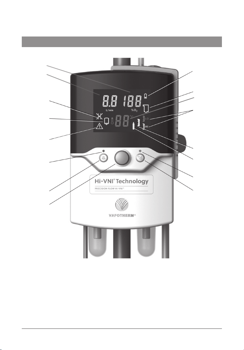
• Firmware running in the main unit uses sensors to monitor gas pressure, water temperature,
and to detect air leaks into the water pathway of the disposable patient circuit (bubble detector).
Alarms are displayed if any parameters are outside the normal range. Other indicators show low
charge in the backup battery, and the type of cartridge installed. See Appendix for a description
of the firmware states and transitions.
• After a two hour charging period, an internal battery backup will maintain the set flow and oxygen
blend for at least 15 minutes without AC power.
Disposable patient circuit
• The disposable patient circuit (DPC) is comprised
of the disposable water path (DWP), vapor transfer
cartridge (VTC) and delivery tube. Conditions in the
circulating water and gas streams are sensed remotely
via the interface between the main unit and the
disposable water path.
• Vapor transfer cartridge. In the cartridge, blended
gas passes through the lumens of hundreds of parallel
hollow fibers made of a specially developed polymer.
Warm water circulates around the fibers and diffuses
as vapor through the fiber material into the gas stream
flowing through each fiber. Unlike most humidifiers,
there is no direct contact between the water and
gas streams. The gas stream leaves the cartridge
saturated with vapor at the set temperature.
Note: Use only approved cartridges from Vapotherm Inc.
WARNING: The back-up battery is designed for temporary use only, when AC power to the
unit has been interrupted. When the Precision Flow®Hi-VNI is running on battery, there is no
heat or humidity provided with the set flow and FiO2and humidity level may drop below safe limits.
After the battery is fully discharged the device will not operate and patient gas flow will cease.
When fully charged, the battery provides at least 15 minutes of power. The battery is not
intended for patient transport.
Air Outlet
Water Outlet
Air Inlet
Water Inlet

Precision Flow Hi-VNI Instructions for Use 3101477-01-EN Rev B Page 9
• Patient delivery tube. The warmed humidified gas
passes through the center of a triple-lumen heated
delivery tube. The center lumen is surrounded by two
outer lumens circulating warmed water to maintain
the temperature of the inner lumen and to minimize
rain- out. A proprietary short nasal cannula is
connected to the end of the delivery tube and passes
the humidified breathing gas to the patient’s nares. It
is normal for non-DEHP PVC tubing to appear slightly
cloudy, or yellow, especially during longer use or
when operated at higher temperatures.
• Disposable water path. The disposable water path
houses a water reservoir, pump, connections for
the vapor transfer cartridge and delivery tube, and
sensor interfaces to the main unit. Water is pumped
past a heater plate through the outer lumens of the
delivery tube. Returning water passes through the
outer jacket of the specially designed vapor transfer
cartridge where some water is lost as vapor to the
gas stream. There is no direct contact between water
and gas flows. The water then returns to the pump
reservoir. Heater power automatically maintains
the set temperature. Water flows into the circuit
from the sterile water supply to replace evaporative
losses in the vapor transfer cartridge. Air is purged
to atmosphere from the circulation via a hydrophobic
filter membrane.
Cross-section of Tubing
Warm Water
Flow Warm Water
Return
Breathing
Gas
Electronic Medical Record (EMR) System Integration
The Precision Flow®Hi-VNI provides outbound interface capabilities that facilitate integration
with Electronic Medical Record (EMR) Systems. The Precision Flow®Hi-VNI does not connect
directly to EMR Systems. Interface of the Precision Flow®Hi-VNI to EMR systems requires the
services and technology of an EMR Integrator. The EMR Integrator provides integration into
the institution’s physical network with interface hardware (wired or wireless device adapters)
and a communication translation engine (Gateway) to translate the Precision Flow®Hi-VNI’s
data output to specific EMR system formats, then validate the functionality of the connection.
Bernoulli Systems (formally Nuvon) and Capsule are the Vapotherm recommended 3rd party
integrators.
See Section 5 for a description of the modes of operation.
Section 3 Principles of operation

Page 10 Precision Flow Hi-VNI Instructions for Use 3101477-01-EN Rev B
Section 4 Controls, displays, & connections
13
1
12
2
11
3
10
4
9
5
8
6
7
Note:The Precision Flow®Hi-VNI has no ON/OFF switch. Plug the unit into a wall outlet to
keep the battery fully charged.
1. Battery low or charging
2. Disposable water path faulty or absent
3. Vapor transfer cartridge type
4. Vapor transfer cartridge fault
5. Gas supply fault
6. Run/Stop Status LED
7. Run/Standby button (see note)
8. Setting control knob
9. Alarm mute button
10. Alarm muted LED
11. General fault
12. Water out
13. Blocked tube
14. Temperature Display
15. Flow Display
16. Oxygen % Display
14
15
16

Precision Flow Hi-VNI Instructions for Use 3101477-01-EN Rev B Page 11
Section 4 Controls, displays, & connections
Front view
1. Folding carrying handle
2. Multi-function display:
• Shows set values for oxygen %, flow
and temperature
• Icons indicate alarm conditions and
device status
3. Alarm mute:
• Press to silence alarms for up to
2 minutes
• LED indicates one or more alarms
are muted
4. Setting control knob:
• Press to select which variable to adjust
• Rotate to adjust to parameter value
• Press again to set value
5. Hinged door:
• Opens to install or remove disposable
water path
6. Status light:
• Amber flashing in Sleep mode
• Amber solid in Standby mode
• Flashing green in Run mode when output
does not match settings
(e.g. during warmup)
• Steady green in Run mode when unit is
operating normally
7. Run/standby button:
• Press to start unit after water, DPC,
and gas are connected
1
2
3
4
5
6
7

Page 12 Precision Flow Hi-VNI Instructions for Use 3101477-01-EN Rev B
Section 4 Controls, displays, & connections
Rear view
1. Hinged door
• Open to install or remove disposable water path
2. Vent
3. Access panel for O2sensor with nurse call/EMR connector (see note)
4. Pole clamp
5. Power cord connection and fuse holder
6. DISS or NIST oxygen connection
7. DISS or NIST air connection
8. Gas inlet filters and traps
Note: Using a permanent marker, write an expiration date on the O2sensor cell
that is one year from the date it is removed from its packaging. Computers or
other equipment should not be plugged into the Nurse Call/EMR Port. Only Nurse
Call / EMR cable (PN# 3100897) shall be used.
1
2
3
4
5
6
7
8

Precision Flow Hi-VNI Instructions for Use 3101477-01-EN Rev B Page 13
Section 4 Controls, displays, & connections
WARNING:
Heater plate may
be hot!
Docking station for disposable water path
Arrows show locations of optical sensor ports.
Do not scratch or scrub the ports.
Do not apply organic solvents or bleach.
Section 5 Modes of operation
Mode Action Indicator light color
Sleep Display in sleep mode, no gas flow Amber
Standby Display flashes 00; parameters can be adjusted, no gas flow Amber
Run Warming to set point temperature, gas flow
Unit operating at set point, gas flow
Flashing green
Solid green
See Appendix for a description of the software operating modes.

Page 14 Precision Flow Hi-VNI Instructions for Use 3101477-01-EN Rev B
Section 6 Initial assembly
Certain accessories must be installed in the Precision Flow®Hi-VNI unit before it can be used.
These will normally be supplied in a separate package from the main unit as some are country-
specific. The power cord plugs into the IEC60320-compliant receptacle on the rear panel.
WARNING: Do not position the Precision Flow®Hi-VNI so that it is difficult to operate the
disconnection of the device.
6a. Oxygen sensor installation
CAUTION:The oxygen sensor is in a sealed
package. Un-sealing the package admits oxygen
to the sensor, which should be replaced after 1
year. Do not open the package until the unit is to
be used. Write the expiration date on the oxygen
sensor cell.
1. Loosen three (3) captive screws from the access
panel. Pull the panel away from the unit.
2. Insert the threaded end of oxygen sensor into port,
and screw into place. Sensor should be hand-tight only.
Do not use tools.
3. Plug sensor cable into connector. Replace cover.
When replacing cover, be certain not to pinch cables.
Do not over-tighten screws.
6b. Inlet gas filter trap assemblies.
Gas inlet filters and traps are supplied in a separate box with the O2sensor and must be
installed before first-time use. The inlet filter and trap assemblies have a quick-disconnect
fitting which connects to the main unit, and a gas fitting for either an oxygen or an air hose.
Note: The quick-disconnect tubes for the oxygen and air filters are different sizes, so that they
can not be connected incorrectly.
WARNING: Never attempt to run the Precision Flow®Hi-VNI unit without the gas inlet filters.
Particles in the inlet gas flow will cause irreparable damage to the mass flow sensors.
Installing the gas inlet filters
1. Push the filter assembly firmly into the correct connector opening until it is fully engaged
and it clicks. The filter can rotate but not pull out. Filter bowls should be vertical (glass
side down) when in use.
Removing gas inlet filter assembly from main unit
Note:It is not normally necessary to remove the inlet filter and trap assemblies (unless
performing preventative maintenance), but shipping and packing are easier if the filters are
detached first.
1. Press the filter assembly into the main unit.
2. Hold the locking ring in place and push it back against the main unit backplate.
3. Pull the filter assembly straight out.
Oxygen Sensor Access Panel

Precision Flow Hi-VNI Instructions for Use 3101477-01-EN Rev B Page 15
Section 7 Setting up
7-1. Hang the sterile water supply from hook on
Vapotherm approved roll stand.
7-2. Attach the unit to Vapotherm approved roll stand
below lowest point of the sterile water supply.
NOTE: The Precision Flow®Hi-VNI oxygen and air supply
inlet fittings are gas-specific to ensure correct connection.
WARNING: Unit weighs 10.6 lb.(4.81kg) To prevent
possible injury or damage from falling, it must be
securely fixed to a Vapotherm approved roll stand,
with the base of the unit not more than 40” (102cm)
above the floor. Fixed rail supports may also be used.
Use with Vapotherm approved roll stands.
7-3. Connect oxygen and air supply hoses to correct
inlets, then connect them to the wall outlets.
7-4. Connect power cord.
7-5. Open the bags containing the disposable water path,
vapor transfer cartridge, and delivery tube, and
assemble them as follows:
7-5-1. Remove the rubber plugs from the vapor transfer cartridge.
Install a high or low-flow vapor transfer cartridge in disposable waterpath as shown.
The vapor transfer cartridge may be inserted either way up. Align the vapor transfer
cartridge ports with the disposable water path openings and press firmly into place.
A High Flow Vapor Transfer Cartridge is shown below. It is indicated with a
REF: PF-VTC-HIGH and blue caps. High Flow Cartridges are for flow rates of 5-40 L/min.
A Low Flow Vapor Transfer Cartridge is shown below. It is indicated with a
REF: PF-VTC-LOW, red caps and the addition of two black stripes. Low Flow
Cartridges are for flow rates of 1-8 L/min.
Oxygen
Power
cord
Pole
clamp

Page 16 Precision Flow Hi-VNI Instructions for Use 3101477-01-EN Rev B
Section 7 Setting up
7-5-2. Connect the delivery tube to the disposable water path as shown.
Press firmly into place.
NOTE:If the door does not close easily, check that the cartridge is installed correctly
and the disposable water path is fully inserted into the docking station.
CAUTION: Do not remove the disposable patient circuit while the unit is operating
7-6. Inserting disposable patient circuit:
7-6-1. Open door to expose the docking station.
7-6-2. Hold disposable patient circuit by its handle,
with the delivery tube downward as shown.
7-6-3. Slide disposable patient circuit downward into
the docking station until it stops.
7-6-4. Press down firmly so there is no gap between the
bottom of the Disposable Water Path and the docking
station floor.
7-6-5. Close door.

Precision Flow Hi-VNI Instructions for Use 3101477-01-EN Rev B Page 17
Section 7 Setting up
7-6-6. General Guidelines
After connecting to the sterile water supply and unclamping the water inlet tube make sure
water is flowing into the disposable patient circuit (DPC). Wait approximately 90 seconds (or
180 seconds if using a hard water bottle) before pressing the Run/Standby button. If screen is
dark, press any button or turn the setting control knob prior to placing in Run mode. Uncoil and
straighten the delivery tube to allow water to more easily flow into the DPC. If air pockets are
observed, gently tap the delivery tube to remove the air. Insufficient water flow may lead to a
temperature out of range alarm. Holding the distal end of the delivery tube below the Precision
Flow®Hi-VNI unit may further assist with water flow into the DPC.
After pressing the Run/Standby button, confirm that water is properly circulating through the
machine by making sure the patient delivery tube is warm across the entire length. If good
circulation cannot be confirmed, check that the water flow is not obstructed by air bubbles in the
water inlet tube connected to the water supply, or in the patient delivery tube. Gently tap and
wiggle the tubing, or lift it up and down in order to remove any air seen in the lines.
Reference Section 12 of the Precision Flow®Hi-VNI Instructions for Use for information regarding
alarms. Additional alarm information:
If a medium priority Water Out Alarm occurs, this may be due to the sterile water supply being
empty, an obstructed inlet tube, or accumulation of air within the DPC. If the sterile water supply
is empty, replace sterile water supply. If the inlet tube is obstructed, straighten the inlet tube. If
necessary, remove and reseat the DPC to ensure that the DPC is fully seated in the Precision
Flow®Hi-VNI unit. Press Run/Standby button to restart the unit. If alarm persists, disconnect
patient from therapy.
The DPC may be used up to 30 days. Circuit life may be less than 30 days, especially when
running at higher flow rates and temperatures which may reduce the useful life of the Vapor
Transfer Cartridge. This typically results in the sterile water bag filling up with air and/or a
cartridge fault alarm occurring due to gas bubbles in the water path.
After addressing any alarm condition, especially those involving an obstruction of the gas or
water flow, check all connections for leaks and make sure the Vapor Transfer Cartridge (VTC) is
fully seated into the DPC.

Page 18 Precision Flow Hi-VNI Instructions for Use 3101477-01-EN Rev B
WARNING: Use high–flow cartridge for flows 5-40 L/min and low-flow cartridge for flows 1-8 L/min.
7-7. Plug in power cord, and check that all the display indicators light up. The Precision Flow®
Hi-VNI performs a self-test:
• all icons and numeric displays light up for a few seconds
• internal sensors and control systems are checked
• if no faults are detected the unit enters STANDBY mode
• “Water Out” icon indicates there is no water in the disposable water path
• status LED is amber (solid)
7-8. The Precision Flow®Hi-VNI unit has three controls.
Run/Standby Button – Places the unit into run or standby mode.
Setting Control Knob - Allows you to adjust the parameters.
Alarm Mute Button – Will intermittently silence alarms
and also dims the display panel.
The Precision Flow®Hi-VNI has three modes. Those are
Sleep, Standby, and Run. In Sleep mode, the unit will
have a blank screen and a flashing amber light showing.
The unit cannot be started from sleep. (Note: If the
unit is in Standby mode and there is no user interaction
with the unit for 5 minutes, the unit automatically enters
Sleep mode).
To put the unit in Standby (from Sleep mode), simply
rotate the blue Control Setting Knob to illuminate the
display. You will see the three parameters of Flow,
percent oxygen, and Temperature. There will also
be a corresponding vapor transfer cartridge indicator
on the lower right hand side which will identify what
type of disposable patient circuit is in place
(Blue/High or Red/Low).
To enter Run Mode (from Standby mode), with the screen illuminated,
simply press and release the Run/Standby Button.
The machine will give a series of 10 beeps, and begin to power up. At this point the
small light above the Run/Standby Button will change from Amber to flashing Green.
During this start up, you will also see two amber alarm indicators illuminated.
This is normal and is part of the Precision Flow®Hi-VNI start up self-test.
7-9. Push or rotate the control setting knob in either direction to light up the display in
STANDBY mode.
7-10. Press the Mute button to change between bright and dim display
(this function is only available if no alarms are active).
7-11. To connect the sterile water supply, remove spike cap and disinfect spike with 70-90%
isopropyl alcohol or equivalent. Firmly insert spike into spike port of the sterile water supply,
avoiding direct hand contact. Unclamp the water inlet tube so that water (>200 ml)
flows into the disposable water path and the “Water Out” alarm icon clears.
(*Wait approximately 90 seconds (or 180 seconds if using a hard water bottle)
before pressing the Run/Standby button).
Section 7 Setting up
Run/Standby
button

Precision Flow Hi-VNI Instructions for Use 3101477-01-EN Rev B Page 19
7-12. Press Run/Standby button to start gas flow, pump and heater.
Press twice if the display is initially blank (once to wake the unit up, and again
to put the unit into run mode). Check that the unit beeps while it tests the disposable
water path and pump (see Notes below).
7-13. If all tests are passed the unit enters RUN mode. Water circulates and fills the delivery
tube. The three numeric displays for flow, temperature and oxygen % display initial
factory settings or the last settings used. The Status LED flashes then shows
continuously green when the unit reaches desired temperature.
NOTES on startup:
• When the Run/Standby button is pressed, the unit enters a detection mode. A prompt
sounds and the disposable water path icon flashes for approximately five seconds.
In this mode the unit inspects the disposable water path to confirm that: a vapor
transfer cartridge is present; the disposable water path is present; and the water level
is correct. Power is then applied to the water pump. After five seconds the unit checks
that the water pump has started and is running at the correct speed.
• If the “water out” icon is displayed and accompanied by an alarm, place unit in standby
and allow DPC to fully prime. Press Run/Standby button.
• Purging of air bubbles from the circulation cannot be seen, because the gas escapes
through a membrane at the top of the DWP, not into the water container.
• Clamp the inlet tube to stop the flow of water into disposable patient circuit
whenever the unit is in standby mode.
To adjust settings: See section 8 (Adjustments)
For alarms and troubleshooting: See section 12 (Alarms)
Section 7 Setting up
Section 8 Adjustments
Flow rate, oxygen %, and temperature are all adjusted
using the setting control knob in the center
of the front panel.
8-1. To enter Adjustment mode, press and release
the setting control knob. One of the three
parameters will flash to show that it is selected
for adjustment. Press the knob repeatedly to
cycle the active selection through flow rate,
oxygen %, and temperature.
8-2. To change the selected variable, rotate the
knob until the desired value is displayed.
Press the knob again to enter this value and
select the next variable.
8-3. If the knob is not rotated for five (5) seconds,
the unit returns to the normal Run mode or
Standby mode. To re-enter Adjustment mode,
press the knob again. Rotating the knob has
no effect unless one of the settings has been
selected and one of the displayed values is flashing. Setting control knob

Page 20 Precision Flow Hi-VNI Instructions for Use 3101477-01-EN Rev B
Section 8 Adjustments
NOTES on settings:
• When gas inlet pressures are less than 40 psi (276 kPa) the full specified range of flows
and oxygen mixtures is not available. The Precision Flow®Hi-VNI detects the actual inlet
pressures and calculates the range of values that can be achieved. An alarm sounds if
the operator attempts to make settings outside this range.
• If oxygen is not connected, the blender setting will be fixed at 21%. If air is not connected
the setting is fixed at 100%. An audio signal sounds if the operator attempts to set any
other value.
• If a HIGH-FLOW cartridge is installed the flow cannot be set below 5 L/min.
• If a LOW-FLOW cartridge is installed the flow cannot be set above 8 L/min.
NOTES on adjustment:
• Transient temperature changes may occur after rapid changes in flow settings.
• During warmup the temperature display shows the actual temperature of the gases being
delivered, not the set value.
• In Run mode the display shows the current set values for flow rate, oxygen %, and
temperature.
• The setting control knob is sensitive to speed. Rotate quickly for large increments and
slowly for small increments.
• If the unit is completely powered down (disconnection of AC power), then the unit will
return to default settings.
Section 9 Connecting to patient
9-1. Wait for the unit to reach 33°C before placing the cannula (applied part) on the end of
the patient delivery tube. The flashing green Status LED becomes steady when the set
temperature is reached.
9-2. Check water level, temperature display, gas flow rate, and oxygen percentage.
9-3. Size cannula (applied part) to patient by ensuring that nasal prongs do not fit tightly into
nares (1/2 the diameter of the nares).
9-4. Attach correct sized cannula (applied part) for the patient and vapor transfer cartridge
onto the delivery tube. Adjust the flow to the desired rate and fit the cannula to the
patient. See appendix table for cannula flow rates. DPC flow ranges are shown in the
table below:
Cartridge Cannula type Operational flow rates
High Flow Adult, pediatric & small adult,
pediatric small* 5-40 L/min
Low Flow
Patients weighing less than 3 Kg
must always be put on Low Flow
Premature, solo, neonatal,
infant, intermediate infant,
pediatric small*
1-8 L/min
*Pediatric small cannula is intended to deliver flows from 1-20 L/min
Table of contents
Other Vapotherm Medical Equipment manuals

Vapotherm
Vapotherm FELIX-1 User manual

Vapotherm
Vapotherm precision flow User manual

Vapotherm
Vapotherm 2000i Instruction Manual

Vapotherm
Vapotherm precision flow Instruction Manual

Vapotherm
Vapotherm Heliox Precision Flow User manual

Vapotherm
Vapotherm Oxygen Assist Module User manual

Vapotherm
Vapotherm precision flow User manual