Operating Instruction Manual Page 15
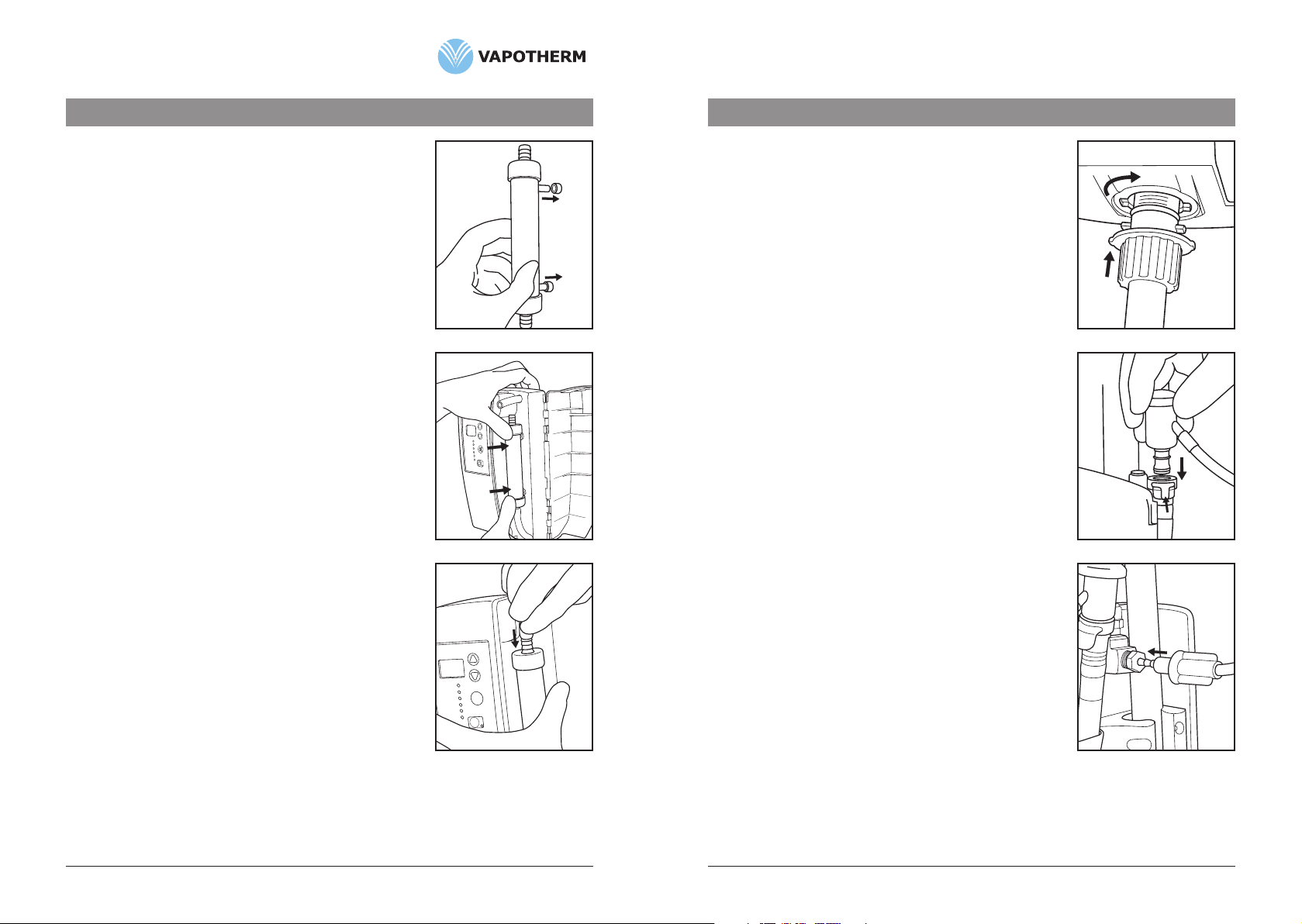
Fig. 1
Fig. 3
Section 6Alarms,TroubleShootingandComponentChange-Outs
6.3 Component Change Outs
WARNINGS:
The vapor transfer cartridge, patient delivery tube, and VSS-1
spike set are all single use only and should be discarded after
removal from the Vapotherm 2000i.
The Patient Delivery Tube, VSS-1 and Vapor Transfer Cartridge
should not be changed or replaced in the patient care area.
The system must be disinfected any time the Vapor Transfer
Cartridge, VSS-1 or Patient Delivery Tube are removed.
NOTE: The cannula and sterile water source can be replaced without
disinfecting the system. As with all respiratory equipment, proper
hand washing techniques should be followed before contacting
or replacing any patient interfaces.
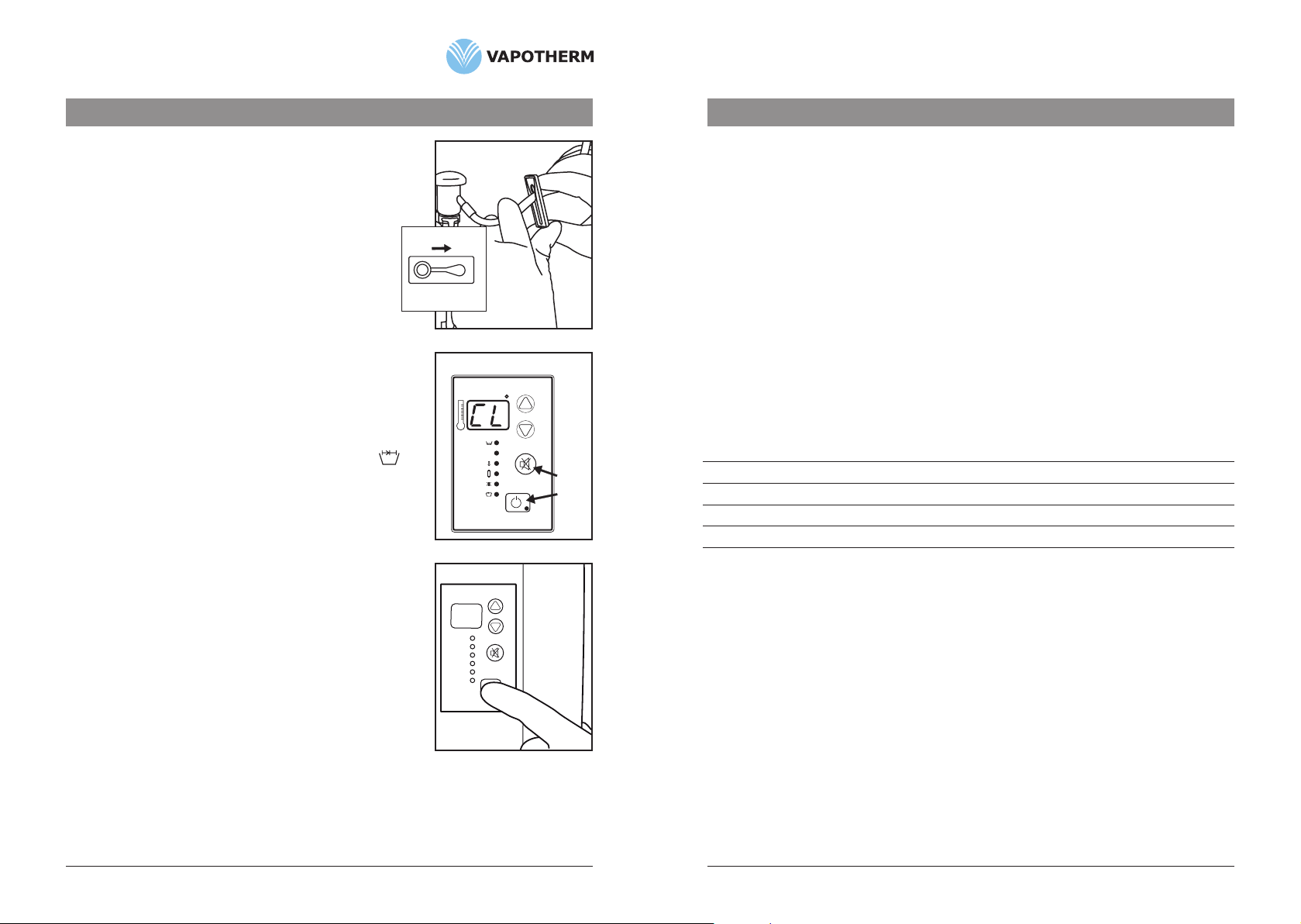
6.3.1 Replacing Vapor Transfer Cartridge
1. Poweroffunit.Disconnectgasflow.
2. ClosecliponVSS-1.(Fig. 1)
3. Openhingedcover.
4. Disconnectairtubesfromcartridgeendsbypressingtubingaway
fromcartridge.
5. Removecartridgebypullingstraightoutwards.(Fig. 2)
6. ProceedtoSection8.0anddisinfecttheVapotherm®2000idevice
beforereturningthedevicetoservice.
7. Forset-uppleaserefertoSection4.3ofthemanual.
CAUTION: Do not grip cartridge tubing with sharp instruments.
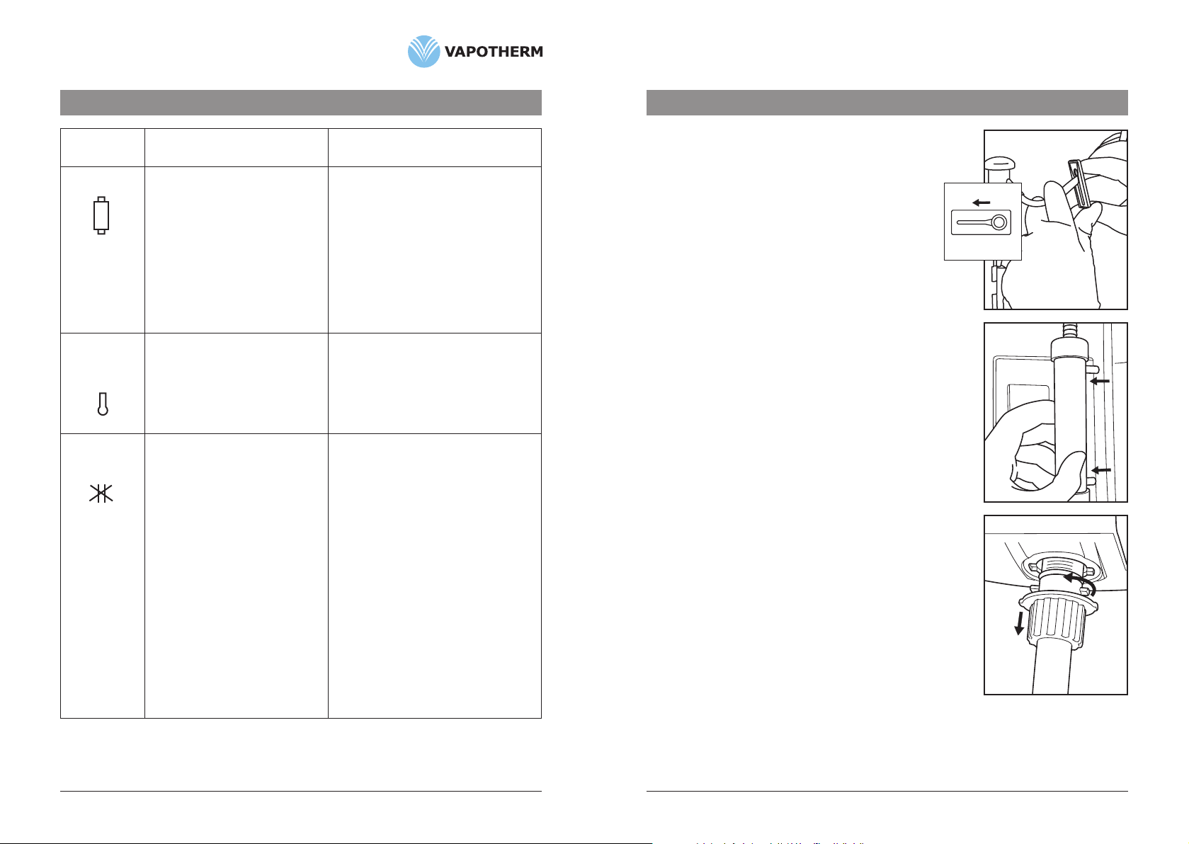
6.3.2 Replacing the Patient Delivery Tube
1. Powerunitoff.Disconnectgasflow.
2. Toremovetube,pushbaseoftubeupwards,rotate1/4turn
counterclockwiseandpulldownward.(Fig. 3)
3. ProceedtoSection8.0anddisinfecttheVapotherm®2000idevice
beforereturningthedevicetoservice.
4. Forset-uppleaserefertoSection4.4ofthemanual.
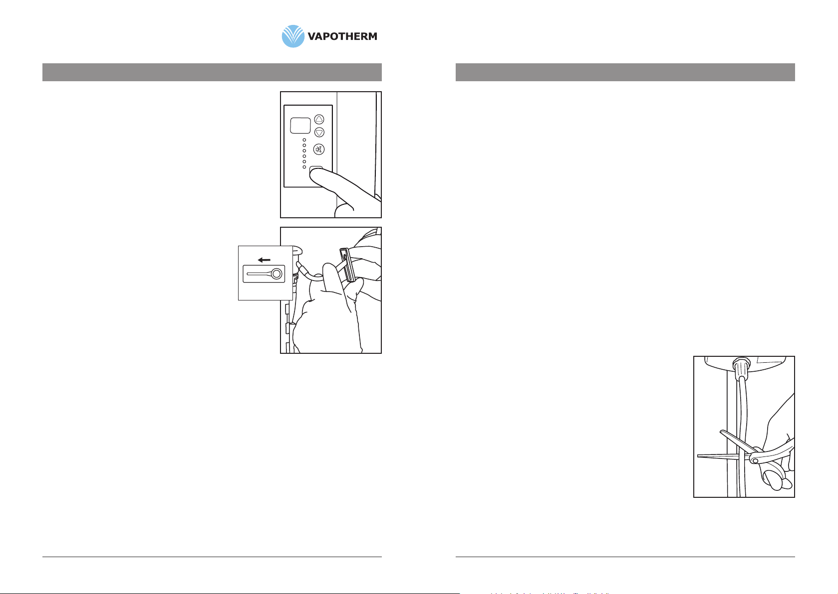
6.3.3 Replacing the VSS-1 Spike Set
1. Poweroffunit.Disconnectgasflow.
2. ClampVSS-1andremoveVSS-1SpikeSetfromthewaterinlet
portonthebackoftheVapotherm2000ibyreleasingthe
quickconnectonthewaterinletport.
3. ProceedtoSection8.0anddisinfecttheVapotherm®2000idevice
beforereturningthedevicetoservice.
4. Forset-uppleaserefertoSection4.5ofthemanual.
Fig. 2
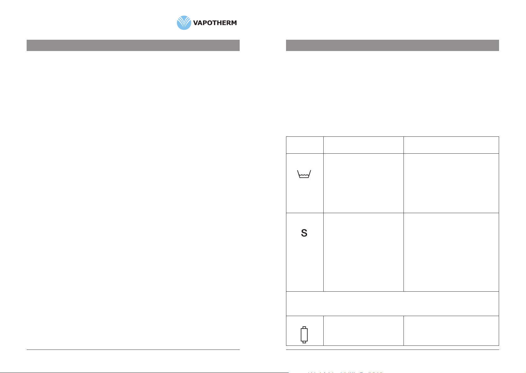
Alarm Cause Action
indication
Operating Instruction Manual Page 14
If further assistance is needed please call your clinical product specialist or local distributor representative.
IftheCartridgeAlarmiscontinuous
and air bubbles are rising into the
VSS-1bubbletraporifaflowor
waterisvisibleinthetubebelow
the cartridge, then the cartridge
hasfailed.
If cartridge alarm is intermittent
and there are no bubbles in the
VSS-1bubbletrapornoobvious
water flow below the cartridge there
maybecondensationinthesystem.
Firstdisconnectthepatientfromtheunit,
shut down unit, drain unit, disinfect unit,
replacecartridge,VSS-1anddeliverytube,
andfollowsetupinstructions.
Occasional brief alarms due to
condensationarenotacauseforconcern.
Trybrieflypinchingandreleasingtube
undercartridgetodislodgethedropsand/
ordecreasesettemperature.
Cartridge
MalfunctionofTemperature
ControlSystem.
Shutdownsystemandreturnforservice.
NOTE: A momentary High Temperature
alarm may occur when the unit has
been switched off and on again. If the
temperature then stabilizes, no action
is needed.
High
Temperature
Alarm
Highwaterorairpressuredueto
high resistance in water circulation
or air outlet: or malfunctioning
pressuresensor.
Blockedtubealarmduetohigh
WATERpressurewillcausea
continuous or intermittent tone
andalarmlight.Theflowof
breathing gas continues, but is
nolongerheated.
Blockedtubealarmduetohigh
GASpressurewillcausea5second
alarmtone.Iftheobstruction
persists the system will continue
toalarmin5secepisodes.Water
circulation continues but the heater
shutsoff.
Checkthatdeliverytubeiscorrectly
positioned, rotated clockwise, and pulled
intolockedposition.Checkthatwateris
circulatingwithindeliverytube.Ifalarm
persistsreplacedeliverytubeand/or
cartridge.Disinfectunitpriortoreplacing
components.
Findandcorrectthecauseofobstruction.
Themostcommoncauseisakinkinthe
nasalcannualorintheprong.Attempting
toruntheVapotherm2000iatveryhigh
flow through a patient interface not
approvedbyVapothermmayalsoraisethe
internal pressure sufficiently to trigger a
BlockedTubeAlarm.
Blocked Tube
Alarm
Section 6Alarms,TroubleShootingandComponentChange-Outs