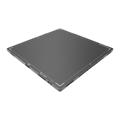
Varex Imaging 4343W User manual

ii
www.vareximaging.com
REFERENCE MANUAL
Before You Begin 4343W/4336W-G5/2530W-G5 X-ray Detectors
Before You Begin
•To avoid personal injury or product damage, read the manual and all accompanying papers
carefully before operating the X-ray detectors.
•The X-ray detectors are intended for use by qualified professional personnel who are trained
and knowledgeable in the use of X-ray detectors, X-ray systems, and electrical equipment.
•Install the X-ray detector horizontally on a flat, stable surface. It is required to use a bucky or
a wall-mount for vertical or tilted positions. The X-ray detector may cause an injury if it falls
or is dropped.
•The User is responsible for using and maintaining the X-ray detector according to prescribed
installation, usage, maintenance, handling, and storage specifications. To keep the X-ray
detector and its accessories in safe and proper condition, only trained and qualified person(s)
shall be in charge of maintenance.
•X-ray imaging, processing, image acquisition, and data storage must be performed in
accordance with all applicable laws. The user is also responsible for compliance to laws
pertaining to the privacy of image data.
•In no event is the X-ray detector manufacturer liable for direct, indirect, or consequential
injury, damage, or loss of equipment operation time or image data arising from the use of the
X-ray detector, its components, and/or accessories.
Protection Against Ionizing Radiation
•Exposure of any part of the human body to X-ray radiation may be harmful to health.
Whenever X-ray equipment, ionizing, or radioactive sources are in use, appropriate safety
precautions and measures shall be instituted, and all regulatory requirements must be met. It
is the responsibility of the X-ray system installer, operator, and user to comply with
applicable requirements.
•The X-ray detectors do not contain a primary barrier for X-rays or Gamma rays. The X-ray
system installer or X-ray system manufacturer must provide the necessary protection based
on the X-ray system’s intended use.
•For portable applications, the X-ray system installer or X-ray system manufacturer must
provide the necessary training for operators to protect themselves, patients, and surrounding
persons.

www.vareximaging.com
iii
4343W/4336W-G5/2530W-G5 X-ray Detectors
For Your Safety
To avoid personal injury or product damage, read this manual and all accompanying
information carefully before handling, installing, or using the X-ray detector. Follow all
instructions, warnings, and cautions in this manual and all warnings and cautions printed on the
warning label. Ignoring instructions, warnings, or cautions in the handling, installing, or use of
the X-ray detector may result in personal injury, death, or product damage. Keep this manual for
future reference.
Meaning of Alerts and Notes
DANGER This indicates a potentially hazardous situation which, if ignored, will
result in severe personal injury, death, or substantial product damage.
WARNING This indicates a potentially hazardous situation which, if ignored, may
result in severe personal injury, death, or substantial product damage.
Caution This indicates a potential hazardous situation which, if ignored, may
result in minor or moderate personal injury or damage to the product.
Note This emphasizes or supplements important information about the
main text.
REFERENCE MANUAL

iv
www.vareximaging.com
REFERENCE MANUAL
Before You Begin 4343W/4336W-G5/2530W-G5 X-ray Detectors
Installation and Environment of Use
WARNING The X-ray detectors are intended to be installed, maintained, and used
by qualified professional personnel who are trained and qualified in
the installation, maintenance, and use of X-ray equipment. All parts of
the X-ray detectors are suitable for use within the patient environment.
The proximity of the X-ray detectors to the patient is dependent upon
the application by the system integrator.
WARNING Do not operate the X-ray detector in or around flammable gases, gas
mixtures, liquids, chemicals, or other substances. Ignoring this
warning may result in explosion, fire, or electric shock, which may
result in severe personal injury, death, or substantial product damage.
WARNING Do not connect the X-ray detector to any component or accessory other
than the manufacturer’s specified components and accessories.
Ignoring this warning may result in explosion, fire, or electric shock,
which may result in severe personal injury, death, or substantial
product damage.
WARNING Do not modify or alter the X-ray detector, its components, or
accessories. Ignoring this warning may result in explosion, fire, or
electric shock, which may result in severe personal injury, death, or
substantial product damage.
WARNING The X-ray detector is not designed to control X-ray dose. The system
integrator is responsible for controlling the X-ray radiation.
WARNING The X-ray detector is not intended to be used as a primary barrier to
X-rays. The user is responsible for ensuring the safety of the operator,
bystanders, and the subjects being radiographed.
WARNING The X-ray detector is not suitable for use in the presence of or in
combination with active implanted devices such as defibrillators and
pacemakers. Doing so may prevent normal operation of these
peripherals.
WARNING For portable applications, the operator and end-user must take
precautions to protect themselves against dangerous X-ray exposure
when using the X-ray detector in the X-ray beam path.
WARNING Portable RF communications equipment should be used no closer than
30cm from the X-ray detector or degradation of performance could
result.
Caution The X-ray detectors have an IP68 ingress protection rating. They are
completely protected against ingress of dust and has protection against
full water immersion for up to 60 minutes, at depths up 1m.

4343W/4336W-G5/2530W-G5 X-ray Detectors
www.vareximaging.com
v
Caution It is important that the X-ray detector is not directly connected to the
installed network. Connection of the X-ray detector with the installed
computer network may disturb the IT environment.
Caution Do not operate the X-ray detector in a location with the following
conditions:
•
Close to fluid or places where fluid is used
•
Close to heat sources, such as a heater
•
High temperature environment
•
High humidity environment
•
High condensation environment
•
Extreme cold environment
•
Dusty environment
•
Salty or sulfurous environment
•
Near a vibrating environment
•
Environment where there is insufficient air circulation to enable the X-ray
detector and power supply to dissipate heat
Ignoring this caution may result in personal injury or damage to
the product.
Caution The X-ray detector is an applied part (patient contact device) and the
surface shall not exceed 42°C. Internal temperature sensor data is
provided in the diagnostic data attached to each image. These
temperature measurements are well correlated with the X-ray detector
external surface temperature. It is advisable to monitor this diagnostic
data as an additional safety precaution, see document
03236 FP2032 - VSP Software Interface. Also, see Table 5.
Note The X-ray detector is intended to be installed, maintained, and used in a
professional healthcare facility.
Caution Monitor the temperature of the X-ray detector and allow the X-ray
detector to cool down when the temperature of the X-ray detector gets
hot. The device is not designed to supply heat to a patient. Ignoring
this caution may result in personal injury or damage to the product.
Caution An Image Quality Test or Customer Acceptance test should be
performed before the X-ray detector is used for the first time with
patients.
No
Caution No part of the X-ray detector is intended to be attached to the patient
and/or contact the patient.
REFERENCE MANUAL

vi
www.vareximaging.com
REFERENCE MANUAL
Before You Begin 4343W/4336W-G5/2530W-G5 X-ray Detectors
Service Cable (4343W) and Tether Cable (4336W-G5 and
2530W-G5)
WARNING Disconnect the Cable by pulling on the connector and not the cable
itself. Ignoring this warning may cause substantial product damage.
WARNING Do not modify the Cable or subject the cable to external stress or
damage. Avoid placing anything heavy, including the X-ray detector,
on the cable, stepping on the cable, pulling the cable, or subjecting the
cable to excessive bending or bundling. Ignoring this warning may
cause cable failure resulting in substantial product damage.
WARNING The Service Cable (4343W) does not support image acquisition. It
should only be used for the following:
•
to retrieve an orphaned image from the X-ray detector, when a wireless
connection is not available
•
for service
Note Varex Imaging tests every X-ray detector, using the tether cable, for com-
munication and link speed defects. Varex’s supplier of the tether cable
individually tests each cable before shipping.

4343W/4336W-G5/2530W-G5 X-ray Detectors
www.vareximaging.com
vii
Handling
WARNING Never disassemble, modify, or alter the X-ray detector, its components,
battery pack, battery charger, or accessories. Ignoring this warning
may cause electrical shock and/or unknown hazards, which may result
in severe personal injury, death, or substantial product damage.
WARNING Do not use the Battery Latch as a handle. Ignoring this warning may
cause damage to the Battery Latch or increase the likelihood that the
X-ray detector may be dropped causing substantial product damage.
Caution Place the X-ray detector horizontally on a flat, stable surface. If the
X-ray detector is placed vertically or in any tilted position, the X-ray
detector must be securely placed in the bucky tray or securely fastened
to the X-ray detector enclosure or support structure. Ignoring this
caution may result in personal injury or damage to the product.
Caution Do not exceed the maximum uniform load weight of 300 kg
distributed across the surface of the X-ray detector.
Caution Do not exceed the maximum load weight of 150 kg distributed on an
area of 40 mm in a diameter of the X-ray detector surface.
Caution Do not drop the X-ray detector. If the X-ray detector is dropped,
remove the X-ray detector from service, and immediately ask your
establishment’s safety representative to verify or re-validate the
proper function of the X-ray detector prior to resuming use of the
X-ray detector. Further use under abnormal conditions may result in
severe personal injury, death, or substantial product damage.
Caution In the event that the X-ray detector is dropped, a new Gain Calibration
must be performed.
Caution Do not expose the backside of the X-ray detector with X-rays. Always
use the top side of the X-ray detector for examinations.
REFERENCE MANUAL

Before You Begin
4343W/4336W-G5/2530W-G5 X-ray Detectors
viii
www.vareximaging.com
REFERENCE MANUAL
Battery, Inductive Charger, and X-ray Detector Power
Supply
WARNING Do not use the battery pack if the casing is broken or if it emits an
unusual odor, smoke, or excessive heat, or if it leaks any substance.
Avoid contact with any substance seeping from the battery pack. If
any fluid touches your skin or eyes, wash the affected area with clean,
running water and immediately seek medical attention.
WARNING The cells within the battery pack contain toxic substances. Do not
attempt to open the battery packs. Do not insert any object into the
battery pack or use any device to pry at the battery pack casing.
Attempting to open the battery pack casing will damage the casing,
which could cause the battery pack to release toxic and harmful
substances causing injuries such as electric shock or burns, or cause a
fire, and will render the pack unusable.
WARNING Be sure to remove the battery before servicing and maintaining.
Do not touch the battery pack, X-ray detector, cable, connector, or any
other electrical component or equipment with wet hands. Ignoring
this warning may cause electrical shock, which may result in severe
personal injury, death, or substantial product damage.
WARNING Do not insert the battery into the X-ray detector when condensation is
on the X-ray detector or any of its components or accessories. Ignoring
this warning may cause electrical shock, which may result in severe
personal injury, death, or substantial product damage.
WARNING Observe and follow all safety information in this manual and on the
warning label found on the battery pack. Ignoring a warning may
result in personal injury or damage to the product.
WARNING Use only charging devices approved by device manufacturer, and
never attempt to bypass or override their charging protection circuits.
WARNING Keep out of reach of children.
WARNING Remove the battery pack from the X-ray detector if the X-ray detector
is not likely to be used for some time.
WARNING Do not submerge the battery pack in water or other liquid.
WARNING Do not charge the battery pack near flammable materials.

4343W/4336W-G5/2530W-G5 X-ray Detectors
www.vareximaging.com
ix
WARNING Do not connect the battery pack to an electrical outlet directly, or to
any other electrical source not described in the manual.
WARNING Do not drop or hit the battery against hard objects since this may cause
damage to the battery pack and risk release of the battery toxic and
harmful substances, causing injuries such as electric shock or burns or
causing a fire, and will render the battery pack unusable.
Caution There is a risk of explosion, personal injury, or damage to product if
the battery pack is replaced by non-OEM approved components.
Caution The Varex provided accessory power supply for tether mode (4336W-
G5 and 2530W-G5) will not introduce noise. An aftermarket power
supply may not be used with the X-ray detector.
WLAN
WARNING Do not obstruct the X-ray detector antenna. If it is obstructed by metal,
wood, or a human body, the wireless communication can be slowed
down or disconnected.
WARNING Do not route Ethernet cables near or with power cables, degradation of
performance could result.
WARNING Follow the laws and regulations for each country and select the
regional code accordingly.
WARNING Do not use the X-ray detector in aircraft because there is a potential
affect to aviation systems.
WARNING Do not modify or alter the X-ray detector as this can violate the
certification of the Radio Law.
Caution Use WLAN access point devices to get the best communication
performance. Please contact your Varex representative for a list of
approved wireless access points.
REFERENCE MANUAL

Before You Begin
4343W/4336W-G5/2530W-G5 X-ray Detectors
x
www.vareximaging.com
REFERENCE MANUAL
Caution The electromagnetic emission of the X-ray detector may influence
implantable medical devices like pacemakers. Check the information
for these devices.
Caution Use a Wi-Fi friendly environment and avoid Bluetooth devices,
mobile phones, and other Wi-Fi devices close to the X-ray detector or
router.
Caution Do not use the 2.4GHz option with the router or access point being
used with the detector. The 2.4GHz band is not available for use with
these detectors.
Network
WARNING Do not connect the X-ray detector to the common IT network, but use a
point-to-point connection or tethered connection with the host
computer or dedicated WLAN access point. Ignoring this warning may
cause unauthorized access to this device.
WARNING Ensure that only authorized users have access to the X-ray detector and
the WLAN access point. Unauthorized access may cause disruption to
the normal operation of the X-ray detector and access point.
vTrigger Mode (Automatic Exposure Detection)
WARNING The vTrigger mode requires a sufficient X-ray dose rate to the X-ray
detector surface to trigger image acquisition. The required dose rate
can vary at different use conditions. The system integrator must
evaluate the vTrigger operation with the complete X-ray setup in order
to secure the proper image acquisition in vTrigger mode.
WARNING vTrigger starts exposure upon detecting X-rays. Before exposure,
software must be switched to a configuration mode that has vTrigger
enabled. Do not expose before the software indicates the X-ray
detector is prepared for acquisition.
WARNING When the X-ray detector is armed, it will time-out if no exposure is
initiated within ten minutes, resulting in the X-ray detector entering
Standby Mode.
WARNING Do not apply any, handling, loading, mechanical shock, or electronic
noise to the X-ray detector while it is in vTrigger mode.

4343W/4336W-G5/2530W-G5 X-ray Detectors
www.vareximaging.com
xi
If a Problem Occurs
WARNING If any abnormal condition, such as smoke, fumes, or strange sounds, is
evident, remove the battery from the X-ray detector, and immediately
ask your establishment’s safety representative to contact your dealer,
distributor, or device manufacturer.
Further use under abnormal conditions may result in severe personal
injury, death, or substantial product damage.
WARNING When liquid has been spilled into or on any part of the X-ray detector
or battery, or when the X-ray detector, its component, or accessory is
dropped, immediately clean the liquid, see Section 14.1.2, and
operation may resume.
Further use under abnormal conditions may result in severe personal
injury, death, or substantial product damage.
Maintenance and Inspection
WARNING Turn off the power of the X-ray detector, see Section 11.7, when the
inspections indicated in this manual are going to be performed.
Ignoring this warning may result in electric shock, which may result in
severe personal injury, death, or substantial product damage.
WARNING When the X-ray detector system is going to be cleaned; remove the
battery pack, cables, and wait until the X-ray detector powers off.
Never use thinner, benzine, acetone, or other flammable cleaning
agents. Ignoring this warning may result in explosion, fire, or electric
shock, which may result in severe personal injury, death, or
substantial product damage.
WARNING The X-ray detector must be repaired by X-ray detector
manufacturer-authorized personnel only. Ignoring this warning may
result in explosion, fire, electric shock, or unknown hazards, which
may result in severe personal injury, death, or substantial product
damage.
Caution Follow the manufacturer’s recommendations for inspecting the X-ray
detector before use.
REFERENCE MANUAL

Before You Begin
4343W/4336W-G5/2530W-G5 X-ray Detectors
xii
www.vareximaging.com
This page intentionally left blank.

www.vareximaging.com
xiii
Table of Contents
1.0 Scope .............................................................................................................................1
2.0 Contraindication............................................................................................................1
3.0 Intended Use..................................................................................................................1
4.0 Audience........................................................................................................................1
5.0 Abbreviations ................................................................................................................2
6.0 References.....................................................................................................................2
7.0 Definition of Symbols ...................................................................................................3
8.0 Standards and Regulations ..........................................................................................5
9.0
Storage and Use Conditions ........................................................................................6
9.1
Temperature Sensors........................................................................................................7
10.0
Description of the X-ray Detectors...............................................................................8
10.1
X-ray Detector Specifications..........................................................................................9
10.2
X-ray Detector Surfaces and Features..........................................................................13
11.0
Getting Started ............................................................................................................16
11.1
Shipment Contents.........................................................................................................16
11.2
Data Interface and Cables..............................................................................................16
11.2.1
Connecting the Service Cable for 4343W....................................................17
11.2.2
Connecting the Tether Cable for 4336W-G5 and 2530W-G5....................19
11.3
Software Installation ......................................................................................................21
11.3.1
SDK Files.........................................................................................................21
11.3.2
Bonjour Installation Files ..............................................................................21
11.3.3
Sample Code...................................................................................................22
11.3.4
Utility Software ..............................................................................................22
11.3.5
ViVA installation............................................................................................22
11.4
X-ray Detector Battery ...................................................................................................23
11.4.1
Battery Installation.........................................................................................23
11.4.2
Battery Removal.............................................................................................24
11.4.3
Battery Charge Level .....................................................................................25
11.4.4
Battery Hot-Swap...........................................................................................25
11.5
Optional Varex Provided Inductive Battery Charger ...............................................26
REFERENCE MANUAL

xiv
www.vareximaging.com
Table of Contents
4343W/4336W-G5/2530W-G5 X-ray Detectors
REFERENCE MANUAL
11.5.1
Installing the Varex Provided Inductive Battery Charger....................... 26
11.6 Using a Third-Party Inductive Battery Charger . . . . . . . . . . . . . . . . . . . . . . . . . . . .
29
11.7 Power-on and Power-off Sequence. . . . . . . . . . . . . . . . . . . . . . . . . . . . . . . . . . . . . . .
30
11.8 Reboot Sequence . . . . . . . . . . . . . . . . . . . . . . . . . . . . . . . . . . . . . . . . . . . . . . . . . . . . . .
31
11.9 LED Status Indicator Behavior . . . . . . . . . . . . . . . . . . . . . . . . . . . . . . . . . . . . . . . . . .
32
11.10 Connecting to the X-ray Detector . . . . . . . . . . . . . . . . . . . . . . . . . . . . . . . . . . . . . . . .
33
11.11 VSP Control Panel. . . . . . . . . . . . . . . . . . . . . . . . . . . . . . . . . . . . . . . . . . . . . . . . . . . . .
34
11.11.1 Access the VSP Control Panel. . . . . . . . . . . . . . . . . . . . . . . . . . . . . . . . . . .
34
11.11.2 Modify Settings. . . . . . . . . . . . . . . . . . . . . . . . . . . . . . . . . . . . . . . . . . . . . . .
36
11.11.3
Change Password . . . . . . . . . . . . . . . . . . . . . . . . . . . . . . . . . . . . . . . . . . . . .
37
11.11.4 Firmware Update . . . . . . . . . . . . . . . . . . . . . . . . . . . . . . . . . . . . . . . . . . . . .
38
11.12 X-ray Detector Calibration. . . . . . . . . . . . . . . . . . . . . . . . . . . . . . . . . . . . . . . . . . . . . .
40
11.12.1 Offset Calibration . . . . . . . . . . . . . . . . . . . . . . . . . . . . . . . . . . . . . . . . . . . . .
40
11.12.2 Offset Calibration Steps . . . . . . . . . . . . . . . . . . . . . . . . . . . . . . . . . . . . . . . .
40
11.12.3 Gain Calibration . . . . . . . . . . . . . . . . . . . . . . . . . . . . . . . . . . . . . . . . . . . . . .
42
11.12.4
Gain Calibration Steps . . . . . . . . . . . . . . . . . . . . . . . . . . . . . . . . . . . . . . . . .
44
11.13 Image Acquisition . . . . . . . . . . . . . . . . . . . . . . . . . . . . . . . . . . . . . . . . . . . . . . . . . . . . .
47
11.13.1 Acquiring Radiography Images . . . . . . . . . . . . . . . . . . . . . . . . . . . . . . . . .
48
11.13.2 Radiographic Acquisition Settings. . . . . . . . . . . . . . . . . . . . . . . . . . . . . . .
51
11.14 ViVA Configuration Settings. . . . . . . . . . . . . . . . . . . . . . . . . . . . . . . . . . . . . . . . . . . .
51
11.15 Dynamic Integration Settings . . . . . . . . . . . . . . . . . . . . . . . . . . . . . . . . . . . . . . . . . . .
54
12.0 The Detector Configuration File . . . . . . . . . . . . . . . . . . . . . . . . . . . . . . . . . . . . . . . . .
56
13.0
System Software. . . . . . . . . . . . . . . . . . . . . . . . . . . . . . . . . . . . . . . . . . . . . . . . . . . . . .
57
13.1
Radiography Acquisition . . . . . . . . . . . . . . . . . . . . . . . . . . . . . . . . . . . . . . . . . . . . . . .
57
13.2 vTrigger Acquisition (AED). . . . . . . . . . . . . . . . . . . . . . . . . . . . . . . . . . . . . . . . . . . . .
58
13.3 X-ray Generator Interface Signals. . . . . . . . . . . . . . . . . . . . . . . . . . . . . . . . . . . . . . . .
59
13.4 Position Sensing. . . . . . . . . . . . . . . . . . . . . . . . . . . . . . . . . . . . . . . . . . . . . . . . . . . . . . .
59
13.5
Autonomous Mode . . . . . . . . . . . . . . . . . . . . . . . . . . . . . . . . . . . . . . . . . . . . . . . . . . . .
60
13.6 Detector Sharing . . . . . . . . . . . . . . . . . . . . . . . . . . . . . . . . . . . . . . . . . . . . . . . . . . . . . .
60
14.0
Maintenance . . . . . . . . . . . . . . . . . . . . . . . . . . . . . . . . . . . . . . . . . . . . . . . . . . . . . . . . .
61
14.1 Cleaning and Disinfecting . . . . . . . . . . . . . . . . . . . . . . . . . . . . . . . . . . . . . . . . . . . . . .
61
14.1.1 Material Compatible Chemicals for Cleaning and Disinfecting . . . . . .
61
14.1.2 Cleaning the X-ray Detector . . . . . . . . . . . . . . . . . . . . . . . . . . . . . . . . . . . .
62
14.1.3 Disinfecting the X-ray Detector . . . . . . . . . . . . . . . . . . . . . . . . . . . . . . . . .
62
14.2 Field Replaceable Parts. . . . . . . . . . . . . . . . . . . . . . . . . . . . . . . . . . . . . . . . . . . . . . . . .
63
15.0
Troubleshooting . . . . . . . . . . . . . . . . . . . . . . . . . . . . . . . . . . . . . . . . . . . . . . . . . . . . . .
64
15.1 After-sales Service for Varex Imaging Products. . . . . . . . . . . . . . . . . . . . . . . . . . . .
68
15.2 Disposing of the X-ray Detector and Battery . . . . . . . . . . . . . . . . . . . . . . . . . . . . . .
68

www.vareximaging.com
xv
4343W/4336W-G5/2530W-G5 X-ray Detectors Table of Contents
16.0
Safety - Electromagnetic Interference .......................................................................69
16.1
Electromagnetic Emissions............................................................................................69
16.2
Electromagnetic Immunity............................................................................................70
16.3
Radio Frequency (RF) Compliance Information........................................................76
16.3.1
United States FCC/IC Compliance .............................................................76
17.0
Regulatory ...................................................................................................................79
17.1
Industry Canada Notice ................................................................................................79
17.2
Declaration of Conformity for European Union........................................................81
17.3
Korea Certification .........................................................................................................82
18.0 Appendix A: Accessories ...........................................................................................83
19.0 Appendix B: Mechanical Drawings ............................................................................ 84
R
EFERENCE MANUAL

Table of Contents
4343W/4336W-G5/2530W-G5 X-ray Detectors
xvi
www.vareximaging.com
This page intentionally left blank.

www.vareximaging.com
xvii
List of Tables
Table 1 Abbreviations....................................................................................................................2
Table 2 References..........................................................................................................................2
Table 3 Definition of Symbols.......................................................................................................3
Table 4 Standards and Regulations..............................................................................................5
Table 5 Environmental Conditions ..............................................................................................6
Table 6 Temperature Sensor Min and Max.................................................................................7
Table 7 Specifications.....................................................................................................................9
Table 8 Description of Detector Surfaces and Features...........................................................13
Table 9 Description of Detector Surfaces and Features...........................................................14
Table 10 Description of Detector Surfaces and Features...........................................................15
Table 11 Battery Hot-Swap Operation Time...............................................................................25
Table 12 LED Status Details..........................................................................................................32
Table 13 Gain Calibration Sequence in ViVA- All Modes ........................................................44
Table 14 Types of Corrections that can be applied during Acquisition..................................47
Table 15 Operational Mode Example ..........................................................................................56
Table 16 Problems and Solutions .................................................................................................64
Table 17 4343W Radiated/Conducted Emissions, Harmonics, Voltage, Fluctuations &
Flicker ...............................................................................................................................69
Table 18 4336W-G5 and 2530W-G5 Radiated/Conducted Emissions, Harmonics, Voltage,
Fluctuations & Flicker.....................................................................................................70
Table 19 4343W ESD, Transient/Burst, Surge, Voltage Variation, Magnetic Fields.............70
Table 20 4343W Test Specs for Enclosure Port Immunity to RF Wireless Communications
Equipment........................................................................................................................72
Table 21 4336W-G5 and 2530W-G5 ESD, Transient/Burst, Surge, Voltage Variation, Mag-
netic Fields........................................................................................................................73
Table 22 4336W-G5 and 2530W-G5 Test Specs for Enclosure Port Immunity to RF Wireless
Communications Equipment.........................................................................................74
Table 23 Europe - Declaration of Conformity in Languages of European Community.......81
Table 24 Korea Certification..........................................................................................................82
Table 25 Accessories.......................................................................................................................83
REFERENCE MANUAL

List of Tables
4343W/4336W-G5/2530W-G5 X-ray Detectors
xviii
www.vareximaging.com
This page intentionally left blank.

www.vareximaging.com
xix
List of Figures
Figure 1 Typical Detector Configuration......................................................................................8
Figure 2 4343W X-ray Detector Surfaces and Features.............................................................13
Figure 3 4336W-G5 X-ray Detector Surfaces and Features.......................................................14
Figure 4 2530W-G5 X-ray Detector Surfaces and Features.......................................................15
Figure 5 X-ray Detector as Access Point .....................................................................................17
Figure 6 X-ray Detector with Router ...........................................................................................17
Figure 7 Service Cable Connection (4343W only)......................................................................18
Figure 8 Remove the Overlay.......................................................................................................19
Figure 9 Remove the Screw and the USB Door..........................................................................19
Figure 10 Tether Cable Connection 4336W-G5 and 2530W-G5 .................................................20
Figure 11 Setup.................................................................................................................................22
Figure 12 Representation of Battery Installation .........................................................................23
Figure 13 Unlatch Battery ...............................................................................................................24
Figure 14 Battery Removal..............................................................................................................24
Figure 15 Battery Charge Level......................................................................................................25
Figure 16 Varex Inductive Battery Charger Dimensions (in mm) and Mounting Hole
Locations (4343W and 4336W-G5 and 2530W-G5).....................................................27
Figure 17 VHB Tape Placement Locations on Varex Inductive Battery Charger....................28
Figure 18 VHB Tape Placement Dimension on Varex Inductive Battery Charger .................28
Figure 19 Third-party Inductive Battery Charger 4343W/4336W-G5/2530W-G5 X-ray
Detector Alignment........................................................................................................29
Figure 20 Reboot Sequence.............................................................................................................31
Figure 21 LED Status Indicator ......................................................................................................32
Figure 22 The ViVA Icon.................................................................................................................33
Figure 23 Detector Linked in ViVA ...............................................................................................33
Figure 24 VSP Control Panel Access Authentication ..................................................................34
Figure 25 VSP Control Panel ..........................................................................................................35
Figure 26 Modify VSP Control Panel Settings .............................................................................36
Figure 27 Change Password ...........................................................................................................37
Figure 28 Updating the Firmware .................................................................................................38
REFERENCE MANUAL

List of Figures
4343W/4336W-G5/2530W-G5 X-ray Detectors
REFERENCE MANUAL
Figure 29 Firmware Updated . . . . . . . . . . . . . . . . . . . . . . . . . . . . . . . . . . . . . . . . . . . . . . . . . . . .
39
Figure 30 Mode Drop Down Menu . . . . . . . . . . . . . . . . . . . . . . . . . . . . . . . . . . . . . . . . . . . . . . .
40
Figure 31 Initiate Offset Calibration. . . . . . . . . . . . . . . . . . . . . . . . . . . . . . . . . . . . . . . . . . . . . . .
41
Figure 32
Calibration Setting window. . . . . . . . . . . . . . . . . . . . . . . . . . . . . . . . . . . . . . . . . . . . .
41
Figure 33 Offset Calibration Progress . . . . . . . . . . . . . . . . . . . . . . . . . . . . . . . . . . . . . . . . . . . . .
41
Figure 34 Finish Offset Calibration . . . . . . . . . . . . . . . . . . . . . . . . . . . . . . . . . . . . . . . . . . . . . . .
42
Figure 35 Mode Drop Down Menu . . . . . . . . . . . . . . . . . . . . . . . . . . . . . . . . . . . . . . . . . . . . . . .
44
Figure 36 Initiate Gain Calibration. . . . . . . . . . . . . . . . . . . . . . . . . . . . . . . . . . . . . . . . . . . . . . . .
44
Figure 37 Gain Calibration Progress window . . . . . . . . . . . . . . . . . . . . . . . . . . . . . . . . . . . . . .
45
Figure 38 Gain Calibration Updating. . . . . . . . . . . . . . . . . . . . . . . . . . . . . . . . . . . . . . . . . . . . . .
45
Figure 39 Gain Calibration Complete . . . . . . . . . . . . . . . . . . . . . . . . . . . . . . . . . . . . . . . . . . . . .
46
Figure 40 Radiographic Acquisition Settings . . . . . . . . . . . . . . . . . . . . . . . . . . . . . . . . . . . . . . .
47
Figure 41 Radiographic Acquisition Settings window . . . . . . . . . . . . . . . . . . . . . . . . . . . . . . .
48
Figure 42 Mode Drop Down Menu . . . . . . . . . . . . . . . . . . . . . . . . . . . . . . . . . . . . . . . . . . . . . . .
48
Figure 43 Acquire Image Button. . . . . . . . . . . . . . . . . . . . . . . . . . . . . . . . . . . . . . . . . . . . . . . . . .
49
Figure 44 Acquire Image . . . . . . . . . . . . . . . . . . . . . . . . . . . . . . . . . . . . . . . . . . . . . . . . . . . . . . . .
49
Figure 45 Start Acquisition . . . . . . . . . . . . . . . . . . . . . . . . . . . . . . . . . . . . . . . . . . . . . . . . . . . . . .
50
Figure 46
Image Acquisition Progress . . . . . . . . . . . . . . . . . . . . . . . . . . . . . . . . . . . . . . . . . . . . .
50
Figure 47 Acquisition Type Drop Down Menu . . . . . . . . . . . . . . . . . . . . . . . . . . . . . . . . . . . . .
51
Figure 48 Mode Drop Down Menu . . . . . . . . . . . . . . . . . . . . . . . . . . . . . . . . . . . . . . . . . . . . . . .
51
Figure 49 Hardware Handshaking Not Selected . . . . . . . . . . . . . . . . . . . . . . . . . . . . . . . . . . . .
52
Figure 50 Hardware Handshaking Selected . . . . . . . . . . . . . . . . . . . . . . . . . . . . . . . . . . . . . . . .
52
Figure 51 Open System Settings . . . . . . . . . . . . . . . . . . . . . . . . . . . . . . . . . . . . . . . . . . . . . . . . . .
53
Figure 52 System Settings window . . . . . . . . . . . . . . . . . . . . . . . . . . . . . . . . . . . . . . . . . . . . . . .
53
Figure 53 Select Mode. . . . . . . . . . . . . . . . . . . . . . . . . . . . . . . . . . . . . . . . . . . . . . . . . . . . . . . . . . .
54
Figure 54 Acquire Image Setup. . . . . . . . . . . . . . . . . . . . . . . . . . . . . . . . . . . . . . . . . . . . . . . . . . .
54
Figure 55
Message Box . . . . . . . . . . . . . . . . . . . . . . . . . . . . . . . . . . . . . . . . . . . . . . . . . . . . . . . . . .
55
Figure 56 Enter Integration Time . . . . . . . . . . . . . . . . . . . . . . . . . . . . . . . . . . . . . . . . . . . . . . . . .
55
Figure 57 Exposure: Corrected Frames . . . . . . . . . . . . . . . . . . . . . . . . . . . . . . . . . . . . . . . . . . . .
57
Figure 58 Exposure: Raw Frames . . . . . . . . . . . . . . . . . . . . . . . . . . . . . . . . . . . . . . . . . . . . . . . . .
58
Figure 59
Position Sensors . . . . . . . . . . . . . . . . . . . . . . . . . . . . . . . . . . . . . . . . . . . . . . . . . . . . . . .
59
Figure 60 4343W Detector and Wireless Label Locations . . . . . . . . . . . . . . . . . . . . . . . . . . . . .
77
Figure 61 4336W-G5 Detector and Wireless Label Locations. . . . . . . . . . . . . . . . . . . . . . . . . .
78
Figure 62 2530W-G5 Detector and Wireless Label Locations. . . . . . . . . . . . . . . . . . . . . . . . . .
78
www.vareximaging.com xx
Other manuals for 4343W
1
This manual suits for next models
2
Table of contents
Other Varex Imaging Security Sensor manuals

Varex Imaging
Varex Imaging Azure 3131Z User manual

Varex Imaging
Varex Imaging XRpad2 HWC-M Series User manual

Varex Imaging
Varex Imaging XRpad2 4343 User manual

Varex Imaging
Varex Imaging 2315NDT User manual

Varex Imaging
Varex Imaging 4343W User manual

Varex Imaging
Varex Imaging PaxScan 1313DXT-I User manual

Varex Imaging
Varex Imaging 2530C-G5 User manual