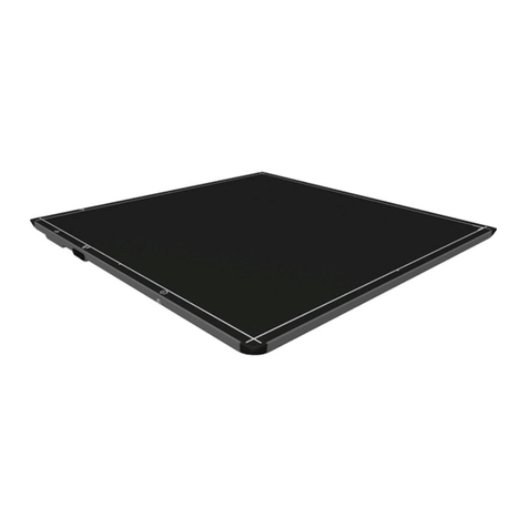
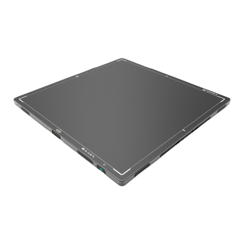
Varex Imaging PaxScan 1313DXT-I User manual

Making the Invisible Visible
PaxScan 1313DXT-I/1515DXT-I/
2520DX-I/3030DX-I
X-ray Detectors
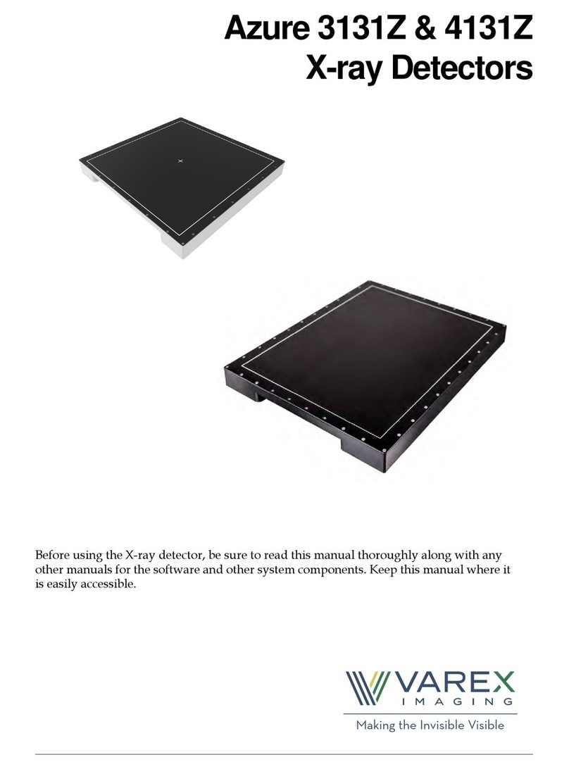
Before using the X-ray detector, be sure to read this manual thoroughly along with any
other manuals for the software and other system components. Keep this manual where it
is easily accessible.

USER MANUAL
ii www.vareximaging.com
Before You Begin1313DXT-I/1515DXT-I/2520DX-I/3030DX-I X-ray Detectors
Before You Begin
•To avoid personal injury or product damage, read the manual and all accompanying papers
carefully before operating the detector.
•The X-ray Detector is intended for use by qualified professional personnel who are trained
and knowledgeable in the use of X-ray Detectors, X-ray systems, and electrical equipment as
well as the safety precautions to avoid possible injuries.
•The user is responsible for using and maintaining the detector according to prescribed
installation, usage, maintenance, handling, and storage specifications. To keep the detector
and its accessories in safe and proper condition, only trained and qualified professional
person(s) shall be in charge of maintenance.
•X-ray imaging, image processing, image acquisition, and data storage must be performed in
accordance with all applicable laws. The user is responsible for compliance to laws
pertaining to the privacy of image data.
•In no event is Varex Imaging liable for direct, indirect, or consequential injury, damage, or
loss of equipment operation time or image data arising from the use of the X-ray Detector, its
components, and/or accessories.
Protection Against Ionizing Radiation
•Exposure of any part of the human body to X-radiation may be harmful to health. Whenever
X-ray equipment, ionizing, or radioactive sources are in use, appropriate safety precautions
and measures shall be instituted, and all regulatory requirements must be met. It is the
responsibility of the X-ray system installer, operator, and user to comply with applicable
requirements.
•The X-ray Detector does not contain a primary barrier for X-rays or Gamma rays. The X-ray
system installer or X-ray system manufacturer must provide the necessary protection based
on the X-ray system’s intended use.
•For portable applications, the X-ray system installer or X-ray system manufacturer must
provide the necessary training for operators to protect themselves, and surrounding persons.
For Your Safety
To avoid personal injury or product damage, read this manual and all accompanying
information carefully before handling, installing, or using the X-ray Detector. Follow all
instructions, warnings, and cautions in this manual and all warnings and cautions printed on the
warning label. Ignoring instructions, warnings, or cautions in the handling, installing, or use of
the detector may result in personal injury, death, or product damage. Keep this manual for
future reference.

USER MANUAL
www.vareximaging.com iii
1313DXT-I/1515DXT-I/2520DX-I/3030DX-I X-ray Detectors
Meaning of Alerts and Notes
Installation and Environment of Use
DANGER This indicates a potentially hazardous situation which, if ignored, will
result in severe personal injury, death, or substantial product damage.
WARNING This indicates a potentially hazardous situation which, if ignored, may
result in severe personal injury, death, or substantial product damage.
Caution This indicates a potential hazardous situation which, if ignored, may
result in minor or moderate personal injury or damage to the product.
Note This emphasizes or supplements important information about the
main text.
WARNING The X-ray Detector is intended to be installed, maintained, and used by
qualified professional personnel who are trained and qualified in the
installation, maintenance, and use of X-ray equipment.
WARNING The detector should be mounted onto user-supplied equipment using
the holes provided in the integral flange.
WARNING
Place the X-ray Detector horizontally on a flat, stable surface. If the
X-ray Detector is placed vertically or in any tilted position, the X-ray
Detector must be securely fastened to the X-ray Detector enclosure or
support structure. Ignoring this caution may result in personal injury
or damage to the product.
WARNING
Do not operate the X-ray Detector in or around flammable gases, gas mixtures,
liquids, chemicals, or other substances. Ignoring this warning may result in
explosion, fire, or electric shock, which may result in severe personal injury,
death, or substantial product damage.
WARNING The metal enclosure of the detector must be connected to earth ground.
WARNING
Do not connect the X-ray Detector to any component or accessory other
than the manufacturer’s specified components and accessories.
Ignoring this warning may result in explosion, fire, or electric shock,
which may result in severe personal injury, death, or substantial
product damage.

USER MANUAL
iv www.vareximaging.com
Before You Begin1313DXT-I/1515DXT-I/2520DX-I/3030DX-I X-ray Detectors
WARNING
Do not modify or alter the X-ray Detector, its components, or
accessories. Ignoring this warning may result in explosion, fire, or
electric shock, which may result in severe personal injury, death, or
substantial product damage.
WARNING The detector is not intended to be used as a primary barrier to X-rays.
The user is responsible for ensuring the safety of the operators,
bystanders, and the subjects being X-rayed.
WARNING The detector is not designed to control X-ray dose. The system
integrator is responsible for controlling the X-ray radiation.
WARNING Operating the detector using X-ray energies above 225kV without
additional external shielding will damage the internal electronics.
WARNING The detector’s active imaging area has a lifetime X-ray radiation
exposure limit of approximately 1MRad.
Caution
Do not operate the X-ray Detector in a location with the following
conditions:
•Close to fluid or places where fluid is used
•Close to heat sources, such as a heater
•High temperature environment
•High humidity environment
•High condensation environment
•Extreme cold environment
•Dusty environment
•Salty or sulfurous environment
•Near a vibrating environment
•Environment where there is insufficient air circulation to enable the X-ray
Detector and power supply to dissipate heat
Ignoring this caution may result in personal injury or damage to
the product.
Caution Monitor the temperature of the X-ray Detector, and allow the detector
to cool down when the temperature of the detector gets hot. Ignoring
this caution may result in personal injury or damage to the product.

USER MANUAL
www.vareximaging.com v
1313DXT-I/1515DXT-I/2520DX-I/3030DX-I X-ray Detectors
Interface and Power Supply and Cables
Caution See “Section 8.7, Environmental Considerations” on page 17 for
temperature and humidity levels. This may necessitate air flow over
the back surface of the detector.
Caution An Image Quality Test or Customer Acceptance test should be
performed before the detector is used for the first time.
Note The detector is designed to be integrated into a complete X-ray system
by a qualified system integrator.
WARNING
Be sure to turn OFF the power of the X-ray Detector, including turning
off the power supply before servicing, maintaining, connecting, or
disconnecting the cables or accessories.
Do not touch the power supply, X-ray Detector, cable, connector, or
any other electrical component or equipment with wet hands. Ignoring
this warning may cause electrical shock, which may result in severe
personal injury, death, or substantial product damage.
WARNING Disconnect the cables by pulling on the connector and not the cable
itself. Ignoring this warning may cause electrical shock, which may
result in severe personal injury, death, or substantial product damage.
WARNING
Do not modify the cables or subject the cable to external stress or
damage. Avoid placing anything heavy, including the detector, on the
cable, stepping on the cable, pulling the cable, or subjecting the cable
to excessive bending or bundling. Ignoring this warning may cause
cable failure resulting in electrical shock, which may result in severe
personal injury, death, or substantial product damage.

USER MANUAL
vi www.vareximaging.com
Before You Begin1313DXT-I/1515DXT-I/2520DX-I/3030DX-I X-ray Detectors
Handling
WARNING
Accessory or optional equipment connected to the analog and digital
interfaces must be certified to the respective IEC standards (i.e. IEC
60950-1 for data processing equipment and IEC 61010 for electrical
equipment for measurement, control, and laboratory use). All
configurations shall comply with the system standard IEC 61010.
Anyone connecting additional or optional equipment to the signal
inputs or signal outputs as part of a configuration is responsible for
compliance with the equipment standard IEC 61010. Consult Varex
technical support personnel with any questions.
WARNING
Do not turn ON the power supply or X-ray Detector when
condensation is on the X-ray Detector or any of its components or
accessories. Ignoring this warning may cause electrical shock, which
may result in severe personal injury, death, or substantial product
damage.
WARNING To avoid risk of electric shock, this equipment must only be connected
to a supply mains with protective earth.
WARNING
Never disassemble, modify, or alter the X-ray Detector, its
components, or accessories. Ignoring this warning may cause electrical
shock and/or unknown hazards, which may result in severe personal
injury, death, or substantial product damage.
WARNING Changes or modifications not expressly approved by the manufacturer
could void the user’s authority to operate the equipment.
WARNING
Do not touch the interface and power supply or cable and the object at
the same time. Ignoring this warning may cause electrical shock and/
or unknown hazards, which may result in severe personal injury,
death, or substantial product damage.
WARNING The detector is not sealed against dripping moisture. All care must be
taken to ensure that moisture does not enter the detector. Failure to do
so will cause the detector to fail and/or cause damage.
Caution Do not exceed the maximum uniform load weight of 150 kg
distributed across the surface of the X-ray Detector.
Caution Do not exceed the maximum load weight of 100 kg distributed on an
area of 40 mm in a diameter of the X-ray Detector surface.

USER MANUAL
www.vareximaging.com vii
1313DXT-I/1515DXT-I/2520DX-I/3030DX-I X-ray Detectors
If a Problem Occurs
Caution
Do not drop the X-ray Detector. If the X-ray Detector is dropped,
remove the X-ray Detector from service, and immediately ask your
establishment’s safety representative to verify or re-validate the
proper function of the X-ray Detector prior to resuming use of the
detector. Further use under abnormal conditions may result in severe
personal injury, death, or substantial product damage.
Caution Do not expose the backside of the detector with X-rays. Always use the
top side of the detector for examinations.
Note The proximity of the detector to the object is dependent upon the
application by the system integrator.
WARNING
If any abnormal condition, such as smoke, fumes, or strange sounds, is
evident, turn off the X-ray Detector, turn off and unplug the power
supply from the AC outlet, and immediately ask your establishment’s
safety representative to contact your dealer, distributor, or device
manufacturer.
Further use under abnormal conditions may result in severe personal
injury, death, or substantial product damage.
WARNING
When liquid has been spilled into or on any part of the X-ray Detector
or power supply (if applicable), or when the X-ray Detector, its
component, or accessory is dropped, unplug the power supply from
the AC outlet, and immediately ask your establishment’s safety
representative to contact your dealer, distributor, or device
manufacturer.
Further use under abnormal conditions may result in severe personal
injury, death, or substantial product damage.

USER MANUAL
viii www.vareximaging.com
Before You Begin1313DXT-I/1515DXT-I/2520DX-I/3030DX-I X-ray Detectors
Maintenance and Inspection
WARNING
Turn off the power of the X-ray Detector when the inspections
indicated in this manual are going to be performed. Ignoring this
warning may result in electric shock, which may result in severe
personal injury, death, or substantial product damage.
WARNING
When the X-ray Detector system is going to be cleaned, turn off the
X-ray Detector and remove the cables. If the X-ray Detector is
connected to a power supply, turn off the power switch and/or unplug
the power supply cable from the AC outlet. Never use thinner,
benzine, acetone, or other flammable cleaning agents. Ignoring this
warning may result in explosion, fire, or electric shock, which may
result in severe personal injury, death, or substantial product damage.
WARNING
The X-ray Detector must be repaired by X-ray Detector
manufacturer-authorized personnel only. Ignoring this warning may
result in explosion, fire, electric shock, or unknown hazards, which
may result in severe personal injury, death, or substantial product
damage.
Caution Follow the manufacturer’s recommendations for inspecting the X-ray
Detector before use.

USER MANUAL
www.vareximaging.com ix
Table of Contents
1.0 Scope . . . . . . . . . . . . . . . . . . . . . . . . . . . . . . . . . . . . . . . . . . . . . . . . . . . . . . . . . . . . . . . 1
2.0 Contraindication . . . . . . . . . . . . . . . . . . . . . . . . . . . . . . . . . . . . . . . . . . . . . . . . . . . . . . 1
3.0 Intended Use . . . . . . . . . . . . . . . . . . . . . . . . . . . . . . . . . . . . . . . . . . . . . . . . . . . . . . . . . 1
4.0 Audience. . . . . . . . . . . . . . . . . . . . . . . . . . . . . . . . . . . . . . . . . . . . . . . . . . . . . . . . . . . . . 1
5.0 Abbreviations. . . . . . . . . . . . . . . . . . . . . . . . . . . . . . . . . . . . . . . . . . . . . . . . . . . . . . . . . 1
6.0 Definition of Symbols . . . . . . . . . . . . . . . . . . . . . . . . . . . . . . . . . . . . . . . . . . . . . . . . . . 2
7.0 Standards and Regulations . . . . . . . . . . . . . . . . . . . . . . . . . . . . . . . . . . . . . . . . . . . . . 3
8.0 Description of the Detectors. . . . . . . . . . . . . . . . . . . . . . . . . . . . . . . . . . . . . . . . . . . . . 4
8.1 Shipment Contents. . . . . . . . . . . . . . . . . . . . . . . . . . . . . . . . . . . . . . . . . . . . . . . . . . . . . . 5
8.1.1 Supporting Files. . . . . . . . . . . . . . . . . . . . . . . . . . . . . . . . . . . . . . . . . . . . . . . . 6
8.2 Accessories . . . . . . . . . . . . . . . . . . . . . . . . . . . . . . . . . . . . . . . . . . . . . . . . . . . . . . . . . . . . 6
8.3 Detector Surfaces and Features . . . . . . . . . . . . . . . . . . . . . . . . . . . . . . . . . . . . . . . . . . . 7
8.3.1 Cables . . . . . . . . . . . . . . . . . . . . . . . . . . . . . . . . . . . . . . . . . . . . . . . . . . . . . . . . 9
8.3.2 Connecting the Cables . . . . . . . . . . . . . . . . . . . . . . . . . . . . . . . . . . . . . . . . . 10
8.3.3 Power On the Detector . . . . . . . . . . . . . . . . . . . . . . . . . . . . . . . . . . . . . . . . . 11
8.4 Detector Dimensions . . . . . . . . . . . . . . . . . . . . . . . . . . . . . . . . . . . . . . . . . . . . . . . . . . . 11
8.5 Electrical Rating . . . . . . . . . . . . . . . . . . . . . . . . . . . . . . . . . . . . . . . . . . . . . . . . . . . . . . . 15
8.5.1 External Power. . . . . . . . . . . . . . . . . . . . . . . . . . . . . . . . . . . . . . . . . . . . . . . . 15
8.6 Detector Specifications . . . . . . . . . . . . . . . . . . . . . . . . . . . . . . . . . . . . . . . . . . . . . . . . . 16
8.7 Environmental Considerations . . . . . . . . . . . . . . . . . . . . . . . . . . . . . . . . . . . . . . . . . . 17
8.8 Interface Signals . . . . . . . . . . . . . . . . . . . . . . . . . . . . . . . . . . . . . . . . . . . . . . . . . . . . . . . 17
8.8.1 User_Sync Input Signal . . . . . . . . . . . . . . . . . . . . . . . . . . . . . . . . . . . . . . . . 17
8.8.2 Expose_OK Output Signal . . . . . . . . . . . . . . . . . . . . . . . . . . . . . . . . . . . . . . 20
9.0 Modes Of Operation. . . . . . . . . . . . . . . . . . . . . . . . . . . . . . . . . . . . . . . . . . . . . . . . . . . 23
9.1 Operational States . . . . . . . . . . . . . . . . . . . . . . . . . . . . . . . . . . . . . . . . . . . . . . . . . . . . . 25
10.0 System Software . . . . . . . . . . . . . . . . . . . . . . . . . . . . . . . . . . . . . . . . . . . . . . . . . . . . . 25
10.1 Software Installation . . . . . . . . . . . . . . . . . . . . . . . . . . . . . . . . . . . . . . . . . . . . . . . . . . . 25
10.2 Detector Files Installation . . . . . . . . . . . . . . . . . . . . . . . . . . . . . . . . . . . . . . . . . . . . . . . 30
10.3 Link to the Detector . . . . . . . . . . . . . . . . . . . . . . . . . . . . . . . . . . . . . . . . . . . . . . . . . . . . 32
10.4 ViVA Mode and System Settings. . . . . . . . . . . . . . . . . . . . . . . . . . . . . . . . . . . . . . . . . 34
10.5 Calibration Procedures . . . . . . . . . . . . . . . . . . . . . . . . . . . . . . . . . . . . . . . . . . . . . . . . . 36

USER MANUAL
x www.vareximaging.com
Table of Contents 1313DXT-I/1515DXT-I/2520DX-I/3030DX-I X-ray Detectors
10.5.1 Offset Calibration . . . . . . . . . . . . . . . . . . . . . . . . . . . . . . . . . . . . . . . . . . . . . 36
10.5.2 Offset Calibration Steps . . . . . . . . . . . . . . . . . . . . . . . . . . . . . . . . . . . . . . . . 37
10.5.3 Gain Calibration . . . . . . . . . . . . . . . . . . . . . . . . . . . . . . . . . . . . . . . . . . . . . . 38
10.5.4 Fluoroscopic Mode Gain Calibration Steps . . . . . . . . . . . . . . . . . . . . . . . 40
10.6 Image Acquisition . . . . . . . . . . . . . . . . . . . . . . . . . . . . . . . . . . . . . . . . . . . . . . . . . . . . . 44
10.6.1 Fluoroscopy 2 × 2 / Full-Res Fluoro 1 × 1 Mode . . . . . . . . . . . . . . . . . . . 44
11.0 Maintenance . . . . . . . . . . . . . . . . . . . . . . . . . . . . . . . . . . . . . . . . . . . . . . . . . . . . . . . . . 46
11.1 Cleaning . . . . . . . . . . . . . . . . . . . . . . . . . . . . . . . . . . . . . . . . . . . . . . . . . . . . . . . . . . . . . 46
11.1.1 Chemicals for Cleaning . . . . . . . . . . . . . . . . . . . . . . . . . . . . . . . . . . . . . . . . 46
11.1.2 Cleaning the X-ray Detector . . . . . . . . . . . . . . . . . . . . . . . . . . . . . . . . . . . . 46
12.0 Troubleshooting. . . . . . . . . . . . . . . . . . . . . . . . . . . . . . . . . . . . . . . . . . . . . . . . . . . . . . 48
12.1 Diagnostic Data . . . . . . . . . . . . . . . . . . . . . . . . . . . . . . . . . . . . . . . . . . . . . . . . . . . . . . . 50
12.2 After-sales Service for Varex Imaging Products. . . . . . . . . . . . . . . . . . . . . . . . . . . . 52
12.3 Disposing of the X-ray Detector . . . . . . . . . . . . . . . . . . . . . . . . . . . . . . . . . . . . . . . . . 53
13.0 Safety. . . . . . . . . . . . . . . . . . . . . . . . . . . . . . . . . . . . . . . . . . . . . . . . . . . . . . . . . . . . . . . 54
13.1 Electromagnetic Compatibility . . . . . . . . . . . . . . . . . . . . . . . . . . . . . . . . . . . . . . . . . . 54
13.2 Electromagnetic Emissions . . . . . . . . . . . . . . . . . . . . . . . . . . . . . . . . . . . . . . . . . . . . . 55
13.3 Electromagnetic Immunity . . . . . . . . . . . . . . . . . . . . . . . . . . . . . . . . . . . . . . . . . . . . . 56
13.4 RF Immunity . . . . . . . . . . . . . . . . . . . . . . . . . . . . . . . . . . . . . . . . . . . . . . . . . . . . . . . . . 57

USER MANUAL
www.vareximaging.com xi
List of Tables
Table 1 Abbreviations . . . . . . . . . . . . . . . . . . . . . . . . . . . . . . . . . . . . . . . . . . . . . . . . . . . . . . . . . . 1
Table 2 Definition of Symbols . . . . . . . . . . . . . . . . . . . . . . . . . . . . . . . . . . . . . . . . . . . . . . . . . . . 2
Table 3 Standards and Regulations . . . . . . . . . . . . . . . . . . . . . . . . . . . . . . . . . . . . . . . . . . . . . . . 4
Table 4 Accessories . . . . . . . . . . . . . . . . . . . . . . . . . . . . . . . . . . . . . . . . . . . . . . . . . . . . . . . . . . . . 6
Table 5 Detector Surfaces and Features . . . . . . . . . . . . . . . . . . . . . . . . . . . . . . . . . . . . . . . . . . . 8
Table 6 Cable Names & Descriptions . . . . . . . . . . . . . . . . . . . . . . . . . . . . . . . . . . . . . . . . . . . . . 9
Table 7 External Power Supply Specification (if supplied with the unit) . . . . . . . . . . . . . . 15
Table 8 Electrical Rating (if power supply not provided with the unit) . . . . . . . . . . . . . . . 15
Table 9 External Power . . . . . . . . . . . . . . . . . . . . . . . . . . . . . . . . . . . . . . . . . . . . . . . . . . . . . . . . 15
Table 10 X-ray Detector Specifications . . . . . . . . . . . . . . . . . . . . . . . . . . . . . . . . . . . . . . . . . . . . 16
Table 11 Environmental Considerations. . . . . . . . . . . . . . . . . . . . . . . . . . . . . . . . . . . . . . . . . . . 17
Table 12 User_Sync Input Activation . . . . . . . . . . . . . . . . . . . . . . . . . . . . . . . . . . . . . . . . . . . . . 17
Table 13 User Sync Pulse Duration and Response . . . . . . . . . . . . . . . . . . . . . . . . . . . . . . . . . . 18
Table 14 Detector Cable 9-Pin D-Sub Pinout for 1313DXT-I/1515DXT-I and 2520DX-I. . . 21
Table 15 Detector Cable 9-Pin D-Sub Pinout for 3030DX-I . . . . . . . . . . . . . . . . . . . . . . . . . . . 21
Table 16 Lemo EXG.1B.308.HLN Pinout 1313DXT-I/1515DXT-I and 2520DX-I . . . . . . . . . 21
Table 17 Lemo EXA.1B.308.HLN Pinout 3030DX-I. . . . . . . . . . . . . . . . . . . . . . . . . . . . . . . . . . 22
Table 18 Operational Mode Examples 1313DXT-I . . . . . . . . . . . . . . . . . . . . . . . . . . . . . . . . . . 23
Table 19 Operational Mode Examples 1515DXT-I . . . . . . . . . . . . . . . . . . . . . . . . . . . . . . . . . . 24
Table 20 Operational Mode Examples 2520DX-I. . . . . . . . . . . . . . . . . . . . . . . . . . . . . . . . . . . . 24
Table 21 Operational Mode Examples 3030DX-I. . . . . . . . . . . . . . . . . . . . . . . . . . . . . . . . . . . . 24
Table 22 Gain Calibration Sequence . . . . . . . . . . . . . . . . . . . . . . . . . . . . . . . . . . . . . . . . . . . . . . 39
Table 23 Problems and Solutions. . . . . . . . . . . . . . . . . . . . . . . . . . . . . . . . . . . . . . . . . . . . . . . . . 48
Table 24 Diagnostic Data. . . . . . . . . . . . . . . . . . . . . . . . . . . . . . . . . . . . . . . . . . . . . . . . . . . . . . . . 50
Table 25 Radiated/Conducted Emissions, Harmonics, Voltage, Fluctuations, & Flicker. . 55
Table 26 ESD, Transient/Burst, Surge, Voltage Variation, Magnetic Fields. . . . . . . . . . . . . 56
Table 27 Conducted/Radiated RF. . . . . . . . . . . . . . . . . . . . . . . . . . . . . . . . . . . . . . . . . . . . . . . . 57

This page intentionally left blank.
xii www.vareximaging.com
List of Tables 1313DXT-I/1515DXT-I/2520DX-I/3030DX-I X-ray Detectors

USER MANUAL
www.vareximaging.com xiii
List of Figures
Figure 1 Customer System . . . . . . . . . . . . . . . . . . . . . . . . . . . . . . . . . . . . . . . . . . . . . . . . . . . . . . . 5
Figure 2 Detector Surfaces and Features . . . . . . . . . . . . . . . . . . . . . . . . . . . . . . . . . . . . . . . . . . . 7
Figure 3 Detector Surfaces and Features . . . . . . . . . . . . . . . . . . . . . . . . . . . . . . . . . . . . . . . . . . . 8
Figure 4 Cable Connections . . . . . . . . . . . . . . . . . . . . . . . . . . . . . . . . . . . . . . . . . . . . . . . . . . . . . . 9
Figure 5 1313DXT-I & 1515DXT-I Detector Dimensions (measured in inches and mm) . . 11
Figure 6 1313DXT-I & 1515DXT-I Detector Dimensions (measured in inches and mm) . . 12
Figure 7 2520DX-I Detector Dimensions (measured in inches and mm). . . . . . . . . . . . . . . . 12
Figure 8 2520DX-I Detector Dimensions (measured in inches and mm). . . . . . . . . . . . . . . . 13
Figure 9 3030DX-I Detector Dimensions (measured in inches and mm). . . . . . . . . . . . . . . . 14
Figure 10 3030DX-I Detector Dimensions (measured in inches and mm). . . . . . . . . . . . . . . . 14
Figure 11 User_Sync Blanking Activated. . . . . . . . . . . . . . . . . . . . . . . . . . . . . . . . . . . . . . . . . . . 18
Figure 12 User_Sync Blanking De-Activated. . . . . . . . . . . . . . . . . . . . . . . . . . . . . . . . . . . . . . . . 19
Figure 13 User_Sync & Expose_OK Signals. . . . . . . . . . . . . . . . . . . . . . . . . . . . . . . . . . . . . . . . . 20
Figure 14 Setup. . . . . . . . . . . . . . . . . . . . . . . . . . . . . . . . . . . . . . . . . . . . . . . . . . . . . . . . . . . . . . . . . 25
Figure 15 License Agreement. . . . . . . . . . . . . . . . . . . . . . . . . . . . . . . . . . . . . . . . . . . . . . . . . . . . . 26
Figure 16 64-bit or 32-bit Installation . . . . . . . . . . . . . . . . . . . . . . . . . . . . . . . . . . . . . . . . . . . . . . 26
Figure 17 Pleora Driver Installation . . . . . . . . . . . . . . . . . . . . . . . . . . . . . . . . . . . . . . . . . . . . . . . 27
Figure 18 Installation Progress window. . . . . . . . . . . . . . . . . . . . . . . . . . . . . . . . . . . . . . . . . . . . 27
Figure 19 eBUS Installation . . . . . . . . . . . . . . . . . . . . . . . . . . . . . . . . . . . . . . . . . . . . . . . . . . . . . . 28
Figure 20 eBUS Installing . . . . . . . . . . . . . . . . . . . . . . . . . . . . . . . . . . . . . . . . . . . . . . . . . . . . . . . . 28
Figure 21 Reboot . . . . . . . . . . . . . . . . . . . . . . . . . . . . . . . . . . . . . . . . . . . . . . . . . . . . . . . . . . . . . . . 29
Figure 22 Installation Complete. . . . . . . . . . . . . . . . . . . . . . . . . . . . . . . . . . . . . . . . . . . . . . . . . . . 29
Figure 23 Detector Files Setup . . . . . . . . . . . . . . . . . . . . . . . . . . . . . . . . . . . . . . . . . . . . . . . . . . . . 30
Figure 24 Welcome Screen for detector setup . . . . . . . . . . . . . . . . . . . . . . . . . . . . . . . . . . . . . . . 30
Figure 25 Choose Install Location Window. . . . . . . . . . . . . . . . . . . . . . . . . . . . . . . . . . . . . . . . . 31
Figure 26 Installation Window Complete . . . . . . . . . . . . . . . . . . . . . . . . . . . . . . . . . . . . . . . . . . 31
Figure 27 The ViVA icon. . . . . . . . . . . . . . . . . . . . . . . . . . . . . . . . . . . . . . . . . . . . . . . . . . . . . . . . . 32
Figure 28 Receptor Setup . . . . . . . . . . . . . . . . . . . . . . . . . . . . . . . . . . . . . . . . . . . . . . . . . . . . . . . . 32
Figure 29 Receptor Selections Window . . . . . . . . . . . . . . . . . . . . . . . . . . . . . . . . . . . . . . . . . . . . 32
Figure 30 Open VCP Link. . . . . . . . . . . . . . . . . . . . . . . . . . . . . . . . . . . . . . . . . . . . . . . . . . . . . . . . 33

USER MANUAL
www.vareximaging.com xiv
List of Figures 1313DXT-I/1515DXT-I/2520DX-I/3030DX-I X-ray Detectors
Figure 31 Detector Linked . . . . . . . . . . . . . . . . . . . . . . . . . . . . . . . . . . . . . . . . . . . . . . . . . . . . . . . 33
Figure 32 Mode Drop Down Menu . . . . . . . . . . . . . . . . . . . . . . . . . . . . . . . . . . . . . . . . . . . . . . . 34
Figure 33 Mode Settings selection in Acquisition menu. . . . . . . . . . . . . . . . . . . . . . . . . . . . . . 34
Figure 34 Mode Settings Window . . . . . . . . . . . . . . . . . . . . . . . . . . . . . . . . . . . . . . . . . . . . . . . . 35
Figure 35 System Settings . . . . . . . . . . . . . . . . . . . . . . . . . . . . . . . . . . . . . . . . . . . . . . . . . . . . . . . 35
Figure 36 System Settings Window . . . . . . . . . . . . . . . . . . . . . . . . . . . . . . . . . . . . . . . . . . . . . . . 36
Figure 37 Select the Desired Mode . . . . . . . . . . . . . . . . . . . . . . . . . . . . . . . . . . . . . . . . . . . . . . . . 37
Figure 38 Offset Calibration Initiation . . . . . . . . . . . . . . . . . . . . . . . . . . . . . . . . . . . . . . . . . . . . . 37
Figure 39 Offset Calibration Progress Window . . . . . . . . . . . . . . . . . . . . . . . . . . . . . . . . . . . . . 38
Figure 40 Mode Drop Down Menu . . . . . . . . . . . . . . . . . . . . . . . . . . . . . . . . . . . . . . . . . . . . . . . 40
Figure 41 Gain Calibration. . . . . . . . . . . . . . . . . . . . . . . . . . . . . . . . . . . . . . . . . . . . . . . . . . . . . . . 41
Figure 42 Gain Calibration Window . . . . . . . . . . . . . . . . . . . . . . . . . . . . . . . . . . . . . . . . . . . . . . 41
Figure 43 Gain Calibration Flat Field Accumulation. . . . . . . . . . . . . . . . . . . . . . . . . . . . . . . . . 42
Figure 44 Dark Field Accumulation Begin . . . . . . . . . . . . . . . . . . . . . . . . . . . . . . . . . . . . . . . . . 42
Figure 45 Gain Calibration Complete . . . . . . . . . . . . . . . . . . . . . . . . . . . . . . . . . . . . . . . . . . . . . 43
Figure 46 Mode Drop Down Menu . . . . . . . . . . . . . . . . . . . . . . . . . . . . . . . . . . . . . . . . . . . . . . . 44
Figure 47 Acquire Image and Radio Button . . . . . . . . . . . . . . . . . . . . . . . . . . . . . . . . . . . . . . . . 44
Figure 48 Buffer Allocation and User Comment Windows . . . . . . . . . . . . . . . . . . . . . . . . . . . 45
Figure 49 Capture Data . . . . . . . . . . . . . . . . . . . . . . . . . . . . . . . . . . . . . . . . . . . . . . . . . . . . . . . . . 45

www.vareximaging.com 1
1313DXT-I/1515DXT-I/2520DX-I/3030DX-I X-ray Detectors
USER MANUAL
1.0 Scope
This document describes the following associated digital X-ray detectors:
•1313DXT-I
•1515DXT-I
•2520DX-I
•3030DX-I
All applicable mechanical, electronic, and software interfaces are described.
2.0 Contraindication
There are no contraindication situations.
3.0 Intended Use
Varex Imaging fluoroscopic digital X-ray detectors and their accessories are designed to be
integrated into systems by X-ray system manufacturers. Manufacturers are responsible for
qualifying, validating, and certifying their products for their intended uses and meeting all
applicable regulatory requirements.
Final application and intended use is determined by the X-ray system manufacturer and is based
on the completed X-ray system design. It is the responsibility of the X-ray system manufacturer
to confirm safety, efficacy and compliance of the X-ray system intended for use, inclusive of the
detector. The Digital Radiography Software referred to in this manual is intended to be used for
development, testing, and maintenance purposes only.
4.0 Audience
This document is for users of the X-ray detector, X-ray System Manufacturers, and X-ray System
Installers who are responsible for installing the X-ray Detector into an X-ray System.
5.0 Abbreviations
Note The detectors are designed to be integrated into a complete X-ray system by
a qualified system integrator.
Table 1 Abbreviations
Abbreviations Descriptions
API Application Program Interface
a-Si Amorphous Silicon
CSI Cesium Iodide

1313DXT-I/1515DXT-I/2520DX-I/3030DX-I X-ray Detectors
2 www.vareximaging.com
USER MANUAL
6.0 Definition of Symbols
CT Computerized Tomography
EMC Electromagnetic Compatibility
L07 Specific version of ViVA software
OEM Original Equipment Manufacturer
RoHS Restriction of Hazardous Substances
RF Radio Frequency
SDK Software Developer Kit
VCP Virtual Command Processor
ViVA Varex Imaging Viewing Application
Table 2 Definition of Symbols
Symbol Description
Serial Number
Temperature Limits
Pressure Limits
Humidity Limits
Protective Earth Ground
Handle with Care
Table 1 Abbreviations (Continued)
Abbreviations Descriptions

www.vareximaging.com 3
1313DXT-I/1515DXT-I/2520DX-I/3030DX-I X-ray Detectors
USER MANUAL
7.0 Standards and Regulations
The X-ray Detectors are designed to be compliant with the requirements detailed in the table
below. All regulatory certificates are valid only if the original accessories as listed in Table 3 are
used. All regulatory certificates are rendered invalid if any modifications to the Product are
made, or any portion thereof, without obtaining the prior written authorization of Varex
Imaging.
Direct Current
Authorized Representative in the European Community/European Union
Manufacturer
Date of Manufacture
Consult Instruction for Use
Do Not Discard with Domestic Waste
European Union Mark of Conformity to Applicable European Directives
Underwriters Laboratory Safety Mark
China RoHS environmentally friendly for 10 years
Interference
Table 2 Definition of Symbols (Continued)

1313DXT-I/1515DXT-I/2520DX-I/3030DX-I X-ray Detectors
4 www.vareximaging.com
USER MANUAL
.
8.0 Description of the Detectors
The detectors described in this user manual incorporate Gigabit Ethernet data communication,
operate at lower power levels, and with improved cycle time. These detectors are specifically
designed to meet the needs of industrial applications utilizing multiple sensitivity ranges. They
acquire images at usual video frame rates over a wide range of dose.
Raw data is normalized for offset and gain variations pixel-by-pixel by the Virtual Command
Processor (VCP) software that comes with the detector. The VCP performs all the interface
functions with the detector such as control, image acquisition and calibration. The VCP also
interpolates the value of any pixels identified as defective. A single-output power supply
provides all the power required for the detector.
VCP software controls the detector operation through Ethernet. System integrators receive a
library of functions for image acquisition and calibration.
Figure 1 displays a customer system showing the configuration of a detector in the context of the
overall imaging system.
Table 3 Standards and Regulations
Standard Description
IEC 61010-1:2010 Part 1 General Requirements (3rd Ed.)
UL 61010-1 Part 1 General Requirements (3rd Ed.)
CAN/CSA 22.2 61010-1-12 (3rd Ed.)
CE Mark Varex Imaging products are designed and manufactured to meet the Low
Voltage Directive 2014/35/EU
Note: The detectors do not contain any applied parts.
Note: A Declaration of Conformity has been filed for this product and available upon request by
contacting Varex Imaging Corporation.

www.vareximaging.com 5
1313DXT-I/1515DXT-I/2520DX-I/3030DX-I X-ray Detectors
USER MANUAL
Figure 1 Customer System
8.1 Shipment Contents
Upon receipt, inspect the shipment and its contents against the Delivery Note enclosed with the
shipment for evidence of damage or missing components. Save all shipping containers in case a
return is warranted. If there is any discrepancy, see “Section 12.2, After-sales Service for Varex
Imaging Products” on page 52.
•One of the described detectors
•Optional external power supply and associated cables, see Table 4 for a list of accessories.

1313DXT-I/1515DXT-I/2520DX-I/3030DX-I X-ray Detectors
6 www.vareximaging.com
USER MANUAL
8.1.1 Supporting Files
This section describes the supporting files shipped with every detector.
•User Manual
•X-ray Detector Files (files specific to the detector in each shipment)
•Software Package
8.2 Accessories
The detectors shall only be used with its approved Varex Imaging accessories and replacement
parts. Product certification and warranty are rendered void if any modifications to the product is
made, or any instruction, warning, or caution is not followed. It is important that the detector is
not directly connected to the installed network. Connection of the detector with the installed
computer network may disturb the IT environment.
Note Supporting files may be physically or electronically delivered. If no physical
files are present in the shipment, please contact your Varex representative
for instructions to download these files.
Table 4 Accessories
Description
Gigabit Ethernet Cable (1.5m/4.9 ft)
Gigabit Ethernet Cable (2m/6.5 ft)
Gigabit Ethernet Cable (6m/19.6 ft)
Gigabit Ethernet Cable (10m/32.8 ft)
Gigabit Ethernet Cable (12m/39.3 ft)
Gigabit Ethernet Cable (15m/49.2 ft)
Gigabit Ethernet Cable (18m/59 ft)
Gigabit Ethernet Cable (25m/82 ft)
110v Hospital Grade Mains Cable (2m/6.5 ft)
European Mains Cable (2.5m/8.2 ft)
Chinese Mains Cable (2.5m/8.2 ft)
Intel Gigabit CT Desktop Adapter
Intel Ethernet Server Adapter, I210
Detector Cable (1m/3.3 ft))
Detector Cable (1.5m/4.9 ft)
Detector Cable (5m/16.4 ft)
This manual suits for next models
3
Table of contents
Other Varex Imaging Security Sensor manuals

Varex Imaging
Varex Imaging 2315NDT User manual

Varex Imaging
Varex Imaging Azure 3131Z User manual

Varex Imaging
Varex Imaging XRpad2 4343 User manual

Varex Imaging
Varex Imaging 2530C-G5 User manual

Varex Imaging
Varex Imaging 4343W User manual

Varex Imaging
Varex Imaging 4343W User manual

Varex Imaging
Varex Imaging XRpad2 HWC-M Series User manual
Popular Security Sensor manuals by other brands

BEMKO
BEMKO SES24WH instructions

STEINEL PROFESSIONAL
STEINEL PROFESSIONAL IS 3360 DALI instructions

Perfect Prime
Perfect Prime AQ9600 instruction manual

Teletek electronics
Teletek electronics SensoMAG F10 Installation instruction

Kolibri
Kolibri Bishop user manual

DELTA DORE
DELTA DORE DOS TYXAL + installation guide