Vari Adela 190 User manual

Brush cutter
BDR-595 GMI
Adela 190
Instructions for use
Contents

BDR-595 GMI Adela 190
2
1 Basic information..............................................................................................................3
2 Introduction.......................................................................................................................4
2.1 Warning. .....................................................................................................................4
3 Operation safety. ...............................................................................................................5
3.1 Safety regulations. ......................................................................................................5
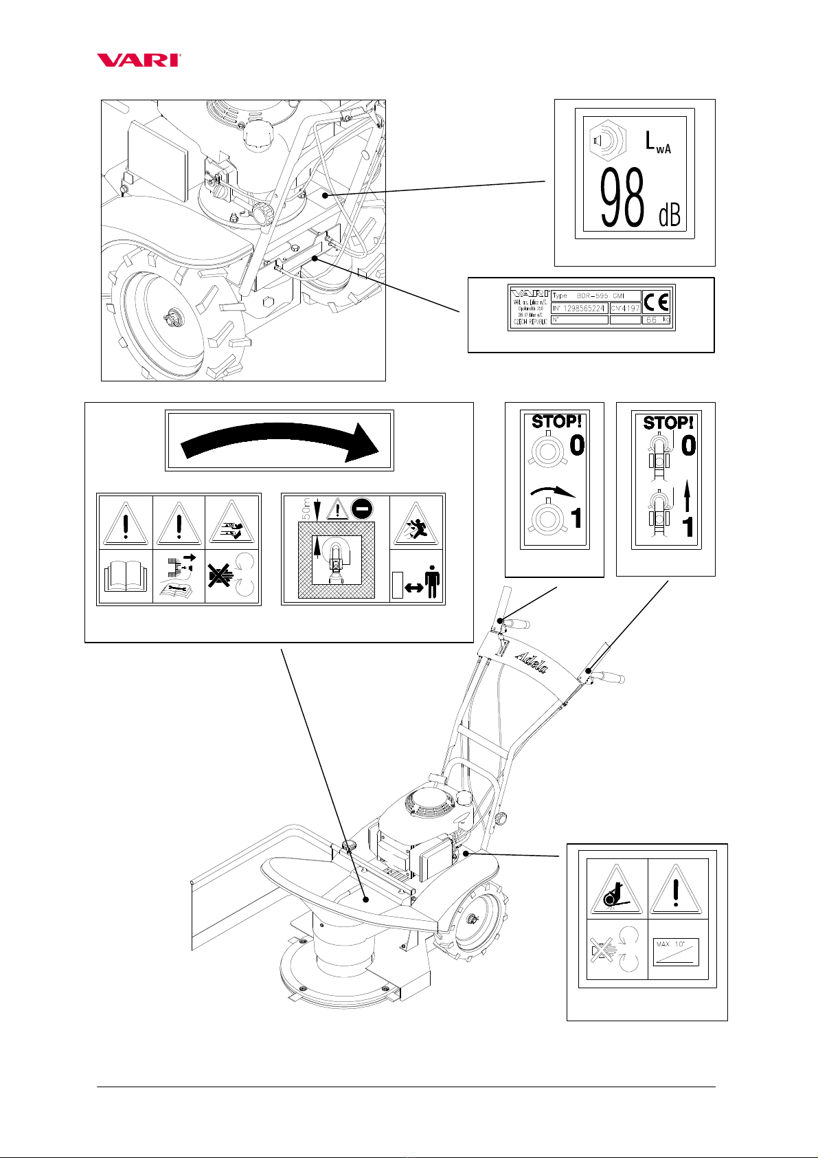
3.2 Declared and guaranteed noise and vi ration values..................................................6
3.3 Safety pictographs. .....................................................................................................6
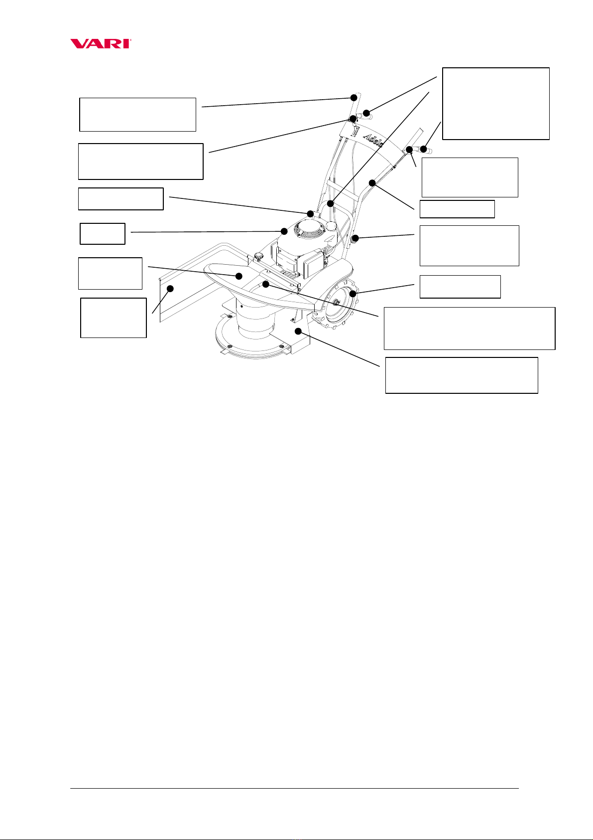
4 Use, technical specification and technical description of the machine.............................8
4.1 Using the machine. .....................................................................................................8
4.2 Technical specification. ..............................................................................................8
5 Instructions for use............................................................................................................9
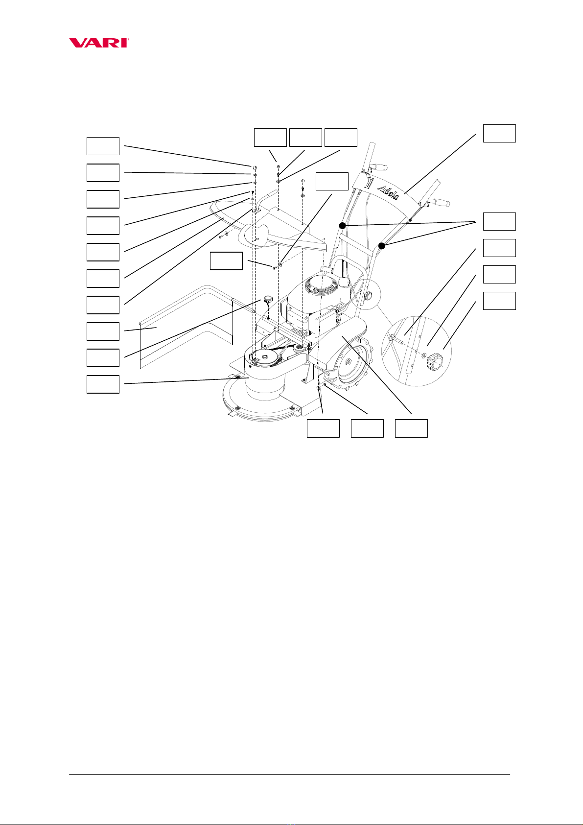
5.1 Assem ling the machine.............................................................................................9
5.2 Putting the machine into operation...........................................................................10
5.3 Starting the cutting disk............................................................................................10
5.4 Machine travel. .........................................................................................................11
5.5 Stopping the machine. ..............................................................................................12
5.6 Working with the machine........................................................................................13
5.6.1 Working width of the machine. ........................................................................13
5.6.2 Cutting the stands. ............................................................................................13
5.6.3 Pro lems at cutting. ..........................................................................................13
6 Maintenance, care and storage. .......................................................................................14
6.1 Machine lu rication..................................................................................................14
6.1.1 Gear ox oil replacement and refilling..............................................................14
6.1.2 Engine oil replacement. ....................................................................................15
6.1.3 Ta le of machine lu rication............................................................................16
6.2 Tightening the olted connections............................................................................17
6.3 Replacement and sharpening the working lades.....................................................17
6.4 V- elt replacement and adjustment of tightening pulley..........................................18
6.5 Adjusting the litz wires of pulley, rake and wheel drive clutch. ............................20
6.6 Diagnostics of driving pro lems...............................................................................21
6.7 Ta le of service operations.......................................................................................22
6.8 Washing and cleaning the machine. .........................................................................22
6.9 Machine storage........................................................................................................23
6.10 Disposal of packaging and machine after the end of service life. ............................23
7 Instructions for ordering spare parts. ..............................................................................24
8 Contact to manufacturer:.................................................................................................24
9 List of components..........................................................................................................24
9.1 Machine casing .........................................................................................................25
9.2 Handle ars ................................................................................................................27
9.3 Cutting disk drive .....................................................................................................29
9.4 Wheel drive...............................................................................................................31
9.5 Gear ox.....................................................................................................................33
10 Letter of Guarantee .........................................................................................................35
Text and illustrations c 2006 VARI,a.s.
Pu lication No. VL-105-2006

BDR-595 GMI Adela 190
3
1 Basic information.
Ask your dealer to provide unpackaging of the machine and briefing
Fill in the following data concerning your machine. The data are important for ordering
spare parts.
It is advised to make a copy of this page with all data on the machine purchase for the
case of a loss or theft of the original record.
Type BDR-595 GMI
Name of the product Adela 190
Engine type HONDA GCV190
Machine Serial no./Year of manufacture
/
Engine Serial no.
Date of delivery (sale)
Supplier
Address
Tel./Fax/E-Mail/Internet
Your notes:
The manufacturer reserves the right of technical changes and innovations not affecting the
machine’s function and safety. The changes may not e reflected in these Instructions for use.

BDR-595 GMI Adela 190
4
2 Introduction.
Dear customer and user,
Thank you for the trust you have shown y purchasing our product. You have ecome
owner of machine from a wide range of machines and attachments made y ,a.s.
as a system of gardening, farming, small agricultural and communal machinery.
Brush cutter BDR-595 GMI Adela 190 is a design follow-up to the drum mower
BDR-595 Adela, very popular on the market thanks to its very easy operation, silent, high-
performing and fuel-saving engine HONDA and also thanks to its capacity of high-quality
cutting of high-grown stands. This new model of the rush cutter retains all these favoura le
properties and com ines them with improved quality and longer service life.
Please read the Instructions for use carefully If you follow the instructions
properly, you will have our product doing a relia le work for you for years.
2.1 Warning.
The user is obliged to get acquainted with the Instructions for use and to follow all
instructions for the machine operation so that the user’s and other persons’ health and
property cannot suffer any harm.
Safety instructions contained in this manual do not descri e all situations or
conditions possi ly occurring in practical use. Safety factors such as common sense,
diligence and scrupulousness are not included; it is assumed, however, that all persons
authorized for the machine operation or maintenance do possess the intelligence.
The machine can e operated only y persons in good mental and physical condition.
For the professional use of the machine the machine owner is o liged to ensure a work safety
training and provide instructions on machine control for operators and to keep records on
these trainings and riefings. Also, the user is obliged to carry out a so-called
categorization of works according to the relevant national legislation
Should some instructions in the manual e unintelligi le, you are encouraged to
contact your dealer or directly the manufacturer of the machine. The contact address and
telephone/fax connection are to e found at the end of the manual.
The manual of Instructions for use supplied with the machine is an integral part of the
machine. It has to e availa le at any time, placed at a well accessi le place with no risk of
its damage. In the case that the machine is sold to another person, the Instructions for use
must e given to the new machine owner. If the a ove conditions are not met, the
manufacturer ears no responsi ility for possi le risks, accidents and injuries resulting from
the machine operation.
The manufacturer ears no responsi ility for damages caused y unauthorized and
incorrect use of the machine and for damages caused y any machine modifications not
authorized y the manufacturer.
To prevent injuries to operators and other people occurring in the vicinity of the
machine, it is a solutely necessary to follow safety regulations marked in the Instructions for
use with the following warning safety sym ol:
If you see the symbol in the manual, read the
attached instructions carefully!

BDR-595 GMI Adela 190
5
3 peration safety.
3.1 Safety regulations.
This international sym ol indicates important messages concerning safety. When you see
the sym ol, e aware of a possi le injury threatening to yourself or to other persons and
read the attached instructions carefully.
The machine operator must e over 18 years of age. He (she) is obliged to get
acquainted with the instructions for use of the machine and is supposed to e informed of
the general principles of work safety.
Prior to carrying out any activities in the near vicinity of the machine, switch the engine
off and wait until the mowing disk stops moving! Before leaving the machine alone,
switch off the engine!
Never let the engine running at maximum speed or idling for a long time with the
mowing disk drive clutch and travel wheels drive clutch switched off! Components of the
machine drive (V- elt, elt pulley, clutch pulley, etc.) might get damaged!
Prior to each employment of the machine, check its parts (working mechanism or its
casing in particular) for a possi le damage or loosening. Defects must be rectified
without any delay. Repairs are to e made only with the original spare parts.
Before using the machine, the stand to e cut must e cleared of solid odies such as
stones, wires, loose construction de ris, etc., which could e flinging up or which might
damage the machine. If these cannot e removed, don’t work the places.
The machine is equipped with a rotating working implement. Maximum circumferential
speed is 60,3 m sec-1. Therefore, make sure that other persons move at a safe distance
from the machine when it is in operation with regard to a possi le flying away of the cut
rushes or solid o jects!
With respect to the exceeded recommended values of noise and vi rations, you are
warned to o serve the following instructions when working with the machine:
a) Protect your hearing y using suita le protective aids specified in CSN EN 352-1
(shell ear protectors) or CSN EN 352-2 (plug ear protectors). Require the aids
from your dealer.
) Working with the machine should e interrupted after max. 20 minutes for a
minimum reak of 10 minutes. During these reaks, the machine operator must
not e exposed to the impact of another source of noise or vi rations.
Machine operators should use working aids authorized to CSN EN 166 or CSN EN 1731
(tight-fitting garments, sturdy shoes, working gloves and protection glasses). Keep a safe
distance given y the handle.
Don’t start the engine in enclosed spaces! Pay increased attention when handling the
machine since the exhaust silencer remains hot after the engine has een switched off;

BDR-595 GMI Adela 190
6
make sure there are no leakages and spills on engine parts when refuelling. If they happen
to occur, dry out the stained parts or wait until the petrol evaporates.
When the machine is in operation, all other persons (children in particular) and animals
have to e outside the machine’s working space. The machine operator can continue
working only after they have een shown out to a safe distance (see Pictograph 6).
NOTE: The outer safety zone A around the inner working zone B is specified in standards
EN 12733 and CSN EN 12733. Entry into the working zone is to e prevented y using
appropriate prohi itory signs. The distance etween the individual sides of zones A and B
must not e less than 50 m. Should the dangerous zone of machine operation e entered y a
person or animal, the machine operator must release the cutting implement drive lever
without any delay and wait with the further work until the zone is clear again.
Removal of any protective equipment and casings from the machine is for idden.
The safe slope accessi ility of the machine is 10°. Maximum inclination of the engine at
work is 20° for a long-time operation and 30° for a shorter time (up to 1 minute).
NOTE: The machine should e prefera ly not used on wet grass. The terrain you are moving
on must e always safe. Do the work while walking not running. Be particularly careful
when changing direction on the slope. Cutting on steeply inclined slopes should e
prevented. If you fall, do not hold the machine ut rather release your grip on it.
All kinds of the machine repair, adjustment, lu rication and cleaning are to e made with
the machine switched off and spark plug ca le disconnected.
3.2 Declared and guaranteed noise and vibration values.
Declared emission level of acoustic pressure A at operator’s site LpAeq,T = 85 dB (according to
CSN EN 836+A1/A2, Attachment H and CSN EN ISO 11 201).
Guaranteed level of acoustic performance of the machine LWA = 98 dB (according to NV No.
9/2002 Gaz.)
Declared sum of accelerated vi rations transmitted onto operator’s hands-arms
ahv = 7,9 + 3,1 [m s-2] (according to CSN EN 836+A1/A2, Attachment G and CSN EN 1033).
3.3 Safety pictographs.
The user is o liged to maintain the pictographs on the machine legi le and to provide for their
replacement in the case of damage.
Pictograph No Safety information-Description
1 La el with data of manufacture
2 Guaranteed level of machine’s acoustic performance
3 Instructions for use to e studied prior to machine operation
4 During the machine maintenance, the conductor is to e disconnected from the spark
plug
5 Putting one’s hands or feet into the cutting disk working space is prohi ited – Danger
of injury
6 Entry for idden for other persons and animals. Minimum safe distance from the
machine
7 Danger of injury y flying off material fragments and flung o jects. Other persons and
animals to e kept at a safe distance from the machine
8 Arrow for the direction of tool rotation – to the right
9 Putting one’s hands into the V- elt space should e avoided – Danger of squeezed
lim s
10 Adhere to a maximum allowed-safe slope accessi ility of the machine
11 Cutting disk drive switch. 0= cutting disk does not turn, 1= cutting disk turns
12 Machine travel switch. 0 = machine stands still , 1 = machine travels

BDR-595 GMI Adela 190
7
2.
1.
8.
3. 4. 5. 6. 7.
11.
12.
9. 10.

BDR-595 GMI Adela 190
8
4 Use, technical specification and technical description of
the machine.
4.1 sing the machine.
Brush cutter BDR-595 GMI Adela 190 is designed and manufactured according to the
latest knowledge in the field of the small gardening and farming machinery. It excels in easy
manoeuvra ility, silent, high-performing and fuel saving engine HONDA, and pro lem-free
maintenance.
The rush cutter is designed to mow grass and cut small-diameter ranches up to max.
100 cm height in the fields, forests and greenlands on well-kept (i.e. annually cut) surfaces
which must not contain solid o jects in the sward or larger terrain uneveness. The rush
cutter is not meant for park treatment of lawns.
Using the machine for purposes other than specified must be therefore considered
to be the use of the machine for purposes unspecified!
The machine can work in all inclined positions defined y the engine manufacturer
provided that the operator is capa le of steering the machine safely oth with respect to the
operator him/her-self and with respect to the surroundings.
Protective equipment and means meet the requirements of standards EN 12733 a CSN
EN 12733. The norms put a crucial emphasis on the safety of the operator who must not e hit
y stones or other o jects flung y the machine’s rotating implement during the normal travel.
This is why the operator is at all times o liged to e in the normal position of steering, i.e.
ehind the machine, holding firm the handle ar grips with oth hands.
Working width has to be always accommodated to the density of the cut brushes
4.2 Technical specification.
BDR-595 GMI Adela 190 Unit Value
Length mm 1550
Width (including side swath-making screen) mm 800
Height mm 1120
Weight kg 66
Maximum working width cm 56
Cutting disk speed (at max. engine revolutions) min-1 2068
Circumferential speed of lades (at max. engine rev.)
m.s-1 60,3
Travel speed (at max. engine revolutions) km.hr-1 2,7
Machine area performance (according to th
e type of
cut stand) m2/hr 800 -1400
Gear ox filling litres 0,15
Oil grade API GL - 4, GL – 5
SAE 90, 80W - 90
Engine Unit Value
HONDA GCV 160 -- --
Cylinder volume cm3 187
Bore x stroke mm 69x50
Max. output at rpm kW/rpm 4,8/3600 (6,5 HP)
Max. torque at rpm N.m/rpm 13,2/2500
Max. adjusted engine speed rpm 3200 (+/-100)
Tank volume litres 1,1
Petrol (leadless) oct.no. 91-95
Oil filling litres 0,55
Oil grade SAE 15W-40
Spark plug -- NKG BPR6ES
-- BRISK LR15YC

BDR-595 GMI Adela 190
9
5 Instructions for use.
5.1 Assembling the machine.
Ask your dealer to provide unpackaging of the machine and riefing.
Grip points for unpackaging the machine from the container: In front on the cutting disk,
Rear on the U tu e of the machine frame.
If you do the machine assem ly yourself, follow the elow instructions:
Note: Washer size (e.g. ∅8.4 mm) is at all times presented as a diameter of washer hole.
1. Take the machine out from the ox and all parts from the packages.
2. Turn the handle ars so that the handrails point to the rear of the machine.
3. Attach the handle ars (1) onto the frame y means of olts with squares (2), washers Ø
8.4 mm (3) and plastic rosettes with internal tread (4) at a required height. Fix Bowdens
to the handrail y using plastic tightening tapes (5).
4. Put the upper casing (6) on the machine and screw it to the machine y using olts
M6x20 (7) with large flat washers Ø 6.6 mm (8). Provide the olt heads with plastic caps
(9).
5. Slide the handgrip (10) on the treaded part of the column (projecting from the upper
casing). Screw the handrail y using a self-locking nut M8 (11) with flat washer Ø8.4
mm (12). The nut M8 should e properly tightened! Provide the nut with a plastic cap
(13).
6. Bolt the upper casing (6) to the metal holder on the lower casing (14) y means of olt
M5x10 (15) and a large flat washer Ø5.5 mm (16). Mudguards (17) are to e screwed to
the upper casing (6) y using olts M6x16 (18), nuts M6 (19) and large flat washers Ø
6.6mm (20).
Travel wheels
Engine
Handle ars
Lever of cutting disk
drive clutch with rake
Accelerator lever (engine
speed setting) Lever of wheel
drive clutch
Plastic
rosette to set
handle ars height
Upper
casing
Figure 1: Brush cutter BDR-595 GMI Adela 190
Starter grip
Side swath
screen Front grip point (for lifting the
machine, etc )
Rear grip points
(for steering, lifting
or loading the
machine)
Safety casing of the working
mechanism

BDR-595 GMI Adela 190
10
7. Slide the apron with the holder (21) into a holder in the frame a ove the right mudguard
and secure it y tightening the plastic rosette with the olt (22).
5.2 Putting the machine into operation.
The machine may be delivered without engine fillings (in dependence on different
national regulations)!
First thoroughly read the instruction for engine use! You can prevent a possible
damage to the engine
1 Check oil volume in the engine and/or fill the engine with the prescri ed oil grade and
volume. Fill the tank with the prescri ed amount and type of petrol.
2 Move the accelerator lever into the front position („CHOKE“). Start the engine y
pulling on the manual starter (instructions for starting see guidelines for engine use).
3 Let the new or cold engine running on choke for a out 30 seconds (accelerator lever in
the „CHOKE“ position), then move the accelerator lever into the position „MAX“. In
this position let the engine running for a out 30 seconds.
Do not leave the machine alone when doing this
5.3 Starting the cutting disk.
When starting the engine, the two levers on the handlebars must be in the off
position
Figure 2: Machine assembly
1
2
3
4
5
6
7
8
9
10
11
12
13
16
15
20
19
17
21
22
18
20
14

BDR-595 GMI Adela 190
11
1 Start the engine while adhering to instructions presented in the operating manual for
engine use.
2 Set-up maximum engine revolutions y using the accelerator lever on the right handrail.
(Should the engine e cold, let it warm up at maximum revolutions for a out 1 minute).
3 Grasp the left handle ar grip with your left hand. Then slowly press the lever of the
cutting disk drive clutch on the right handle ar grip with your right hand.
Press the lever slowly up to about two thirds of the stroke so that the cutting disk can
start rotating and the engine does not stall
Starting of the cutting disk is accompanied with a partial V- elt slippage and with the
accompanying phenomena such as whistling, rattling, etc. The phenomenon usually
disappears after the elt has started properly moving.
4 After the cutting disk starts turning, press the lever fully to the handrail and hold it firm.
Note: In a new or cold engine, a few of the cutting disk starts may result in engine
stalling. The phenomenon will disappear after the engine warms up. If the disk drive cannot
e started even after the engine has got warm, follow the ta le presented in Chapter 6.6 for
diagnostics.
5.4 Machine travel.
The machine travel is switched on y the lever on the left handrail. Press the lever down
to the rail and the machine will immediately start moving forward. While pressing the lever
and o serving the machine to move forward, you have to start walking slowly.
Be prepared to a possible slight jerk when the machine starts moving
Lever of the cutting disk
drive clutch and rake
Lever of wheel
drive clutch
Accelerator lever
(engine speed
adjustment)
Bowden ca le of the wheel
drive
clutch
Bowden ca le of the
cutting disk rake
Bowden ca le of the
cutting disk drive V-
elt tightening
pulley
Right handle ar grip
Left handle ar grip
Figure 3: Handlebars and accelerator lever

BDR-595 GMI Adela 190
12
Note: All four main positions of the accelerator lever are arrested y means of a simple
system of stamp/projection in the lever ody.
5.5 Stopping the machine.
Prior to carrying out any work in the near vicinity of the machine, switch off the
engine and wait until the cutting disk stops! Always switch the engine off before
leaving the machine!
Never let the engine running at maximum speed or idling with the cutting disk drive
clutch released and with the released clutch of wheel drive for a long time! Machine
drive components (V-belt, belt pulley, clutch pulley, etc ) might get damaged!
If you wish to stop the machine travel, release the lever on the left handle ar grip. The
machine travel will stop ut the mowing disk is still rotating. The cutting disk drive will
switch off immediately after you will have released the lever on the right handle ar grip. The
cutting disk will e stopped y the safety rake.
Engine is to e switched off y pushing the lever into the STOP position.
In the case of any critical situation, release your hold on the handlebars
immediately The levers will return to their zero position, the machine and the
cutting disk will come to a stop (while the engine is still running at the adjusted
revolutions; this is why it is advised to switch it off by pushing the lever into the
STOP position as soon as possible!)
STOP position of accelerator lever
- engine stands still
MIN (turtle) position of accelerator lever
–
engine runs idle
MAX (hare) position of accelerator lever
–
engine runs at maximum speed
CHOKE position of accelerator lever
(for cold
engine start only) – engine runs on choke

BDR-595 GMI Adela 190
13
5.6 Working with the machine.
5 6 1 Working width of the machine
Prior to the machine use, the stand must be cleared of solid bodies such as stones,
wires, loose construction debris, etc , which could be flung or might otherwise
damage the machine Should these be impossible to remove, working of the places
should be avoided
Cutting width has to be at all times accommodated to the density of the stand!
Warning:
Particularly when cutting in uneven terrains,
make sure that the lower disk permanently
slides on the ground and does not re ound.
Disk re ounding results in poor stu le
quality and uneven stand cutting.
5 6 2 Cutting the stands
Set the engine on the maximum speed, let the cutting disk rotate at the maximum speed
(starting the cutting disk see Chapter 5.3) and then get the machine into motion (see Chapter
5.4), facing the stand to e cut. Cut grass or rushes are thrown away y the cutting disk to
the right side onto the side screen which forms a swath.
At cutting, you should proceed only in such a way that the to-be-cut stand is at all
times on the left side of the machine (see the picture).
At cutting on slopes it is advised to steer the machine along the slope contours Pay
attention to a maximum permissible long-term machine inclination of 20° (30° over a
short-term)!
If the cut stand is very dense, grown through, rotten from elow or lodged, the machine
working width must e reduced accordingly so that the cutting disk rotations are not
excessively reduced and the cutting quality impaired.
5 6 3 Problems at cutting
Choking of the cutting disk cover space with the cut material manifests as follows:
a) Engine markedly losing speed but not stalling: machine travel to e switched off
immediately (lever on the left handrail grip); move ackwards just a it with a simultaneous
slight lifting of the machine front ( y pushing down on the handle ar handrails). The space
Uncut stand
Side swath screen
Max. working width of
the machine: Edge of the
uncut
stand is a out 5
cm from the right side of
the upper plastic cover

BDR-595 GMI Adela 190
14
under the cutting disk cover will do itself a partial clearance of the excessive grass and
de ris. Then drive the machine against the sward again (see Chapter 5.4).
Be very careful while lifting the machine and moving the machine backwards!
) Engine losing speed and stalling: release oth levers on the handle ars, lift the machine
front y pushing down on the handle ars and move the machine a it ackwards. Clear the
space under the cutting disk casing and spread the cut grass across the ground. Start the
engine, switch on the cutting disk drive (see Chapter 5.3) and once again drive the machine
against the sward (see Chapter 5.4).
The engine must be always switched off when clearing the space under the upper
casing!
Tilt the machine always only backwards onto the handlebars Be very careful while
moving under the lifted machine! Secure the machine against its spontaneous
motion!
Be very careful while cleaning the space under the cutting disk casing Cutting edges
of the blades are sharp You should wear protective gloves or use a suitable piece of
branch etc
6 Maintenance, care and storage.
To ensure a long-term satisfaction with our product, it must e given proper care and
maintenance. Regular maintenance of the machine will prevent its early wear ensuring at the
same time a correct functioning of all its parts.
Follow all instructions for intervals of machine maintenance and adjustments. It is
advised that you keep records on the num er of machine working hours and on the
conditions in which the machine was working (for service purposes). Similarly as the current
maintenance, the after-season maintenance of the machine should e entrusted to one of our
authorized service workshops in the case that you do not trust your own technical skills.
Regarding the machine weight, all maintenance and adjustment procedures are to
be done by two cooperating persons
6.1 Machine lubrication.
6 1 1 Gearbox oil replacement and refilling
When replacing oils, follow the basic hygienic principles, regulations and laws on
environment protection
The gearing works in an oil ath. Oil volume should e checked once a month (oil
plugs see Fig. 4).
Minimum grade of gear oil should e GL-4, GL-5 according to API, 90 or 80W – 90
according to SAE.
Oil replacement in a new machine is to e made after the first 5 hours of operation and
then after 100 working hours or after the end of the season. This will ensure that the gears

BDR-595 GMI Adela 190
15
will not suffer excessive wear. The exchange interval can e extended up to 130 hours with
oils of higher grades (API GL – 5, SAE 80W – 90). The running-up period of 5 hours must
e o served.
Czech oils fully meeting the requirements are MOGUL TRANS 90 or MOGUL TRANS
80W-90.
Oil replacement should e made when the ox is warm and oil is easy to drain.
1. Clean around the oil plugs. Underlay the machine and secure it so that a space is created
under the machine for a vessel to collect oil.
2. Loosen the pour-in plug on the rear wall of the ox and the drain plug in the ottom of
the gear ox (spanner No. 19).
3. After the oil has een drained, screw ack the drain plug in the ottom of the ox. Fill the
gear ox with the new oil (it is advised to use a funnel with flexi le tu ing). Oil level
should reach to the lower edge of the hole. Then screw the pour-in plug ack. If the seals
under the plugs are damaged, replace them with new ones.
6 1 2 Engine oil replacement
See the operating manual for engine. To drain oil, the machine should e either tilted
to the side with the pour-in neck with oil gauge, or the engine should e dismounted from
the machine (see Chapter 6.4, items a), ),d) ).
Plug to pour oil into the
gear ox
Plug to drain oil from the gear ox
Figure 4: Oil plugs

BDR-595 GMI Adela 190
16
6 1 3 Table of machine lubrication
Both swivel seatings of rotary lever in
the gear ox
min 1x
monthly * yes silicone oil in
atomizer 5.1
Tightening pulley arm pin
(after disassem ly of upper casing) min 2x yes grease,
engine oil 5.2
Brake lever seating near the front elt
pulley (accessi le after disassem ly of
upper casing)
min 2x yes grease,
engine oil 5.3
* besides these intervals for lubrication during season, grease these places after each machine washing,
especially when using pressure water!
Machine lubrication During
season
After
season Lubricant Figure no
All ca les
- on the input to Bowdens
- on the output from adjustment olts
min 2x *
min 2x *
yes
yes
silicone oil in
atomizer -
Figure 5 2: Tightening pulley arm pin
Figure 5 1: Rotary clutch lever
Figure 5 3: Brake lever seating
Figure 5: Lubrication points

BDR-595 GMI Adela 190
17
6.2 Tightening the bolted connections.
Check the olted connections for their proper tightening. Prior to each machine use,
check the tightening of olts fastening the lades in the upper disk as well as the tightening of
olts fastening the lower disk onto the flange.
6.3 Replacement and sharpening the working blades.
If the cutting edges of working lades show wear or a damage to the lades results in
machine vi rations, the cutting edges must e renewed or the lades replaced.
The machine must be standing on a firm support plate and must be secured so that
the blade can be easily accessible and an unexpected spontaneous machine motion
cannot occur
Be very careful when dismounting the blades Their cutting edges are sharp Protect
your hands with working gloves
The engine must be switched off and the cable end connector to the spark plug
disconnected!
1. Hold the upper disk so that it does not turn and dismount the lade olted connection y
using arrel spanner No. 16 and flat wrench No. 17.
2. Take the lade and parts of the lade seating out of the cutting disk. Level and sharpen
the lade cutting edges. Inclination of the sharpened cutting edge should e 30° with
respect to the lower plane of the lade.
Should some of the blades be bent or showing a considerable wear, you must always
replace all blades in the cutting disk!
3. Screw ack the olt with the slid-on filler, lade and flat washer. Than screw on the nut.
4. Hold the olt head with arrel spanner No. 16 and firmly tighten the nut. All lades must
freely rotate on the olts. The lades are provided with cutting edges on oth sides; when
one side is worn out, the lade can e reversed and the cutting edge of the other side can
e used. When replacing the lade, all damaged parts of the lade clamping are to e
replaced, too (see Fig. 6).
NOTE: Manufacturer does not answer for damages caused during the machine operation
if the lades were repaired y unskilled persons without the use of the original spare parts.
There is a “VARI“ stamp on the lade, which identifies the manufacturer and is at the same
time a control mark indicating that the lade is an original spare part.

BDR-595 GMI Adela 190
18
6.4 V-belt replacement and adjustment of tightening pulley.
V- elt should e replaced according to its wear (cracked sides, torn elt, sides worn out
down to elt carrier fi res, elt “pulled“ out of shape) or after a out 100 hours of operation at
the maximum. In this machine, the elt pulled out to maximum is considered a elt in which
distance etween inner elt surfaces (at the pressed lever of mowing disk drive clutch) is less
than 7 mm (see Fig. 7).
The replacement procedure is as follows:
a) Drain petrol from the engine tank. Dismount the accelerator lever (2x spanner No. 8)
from the handle ars. Bowden ca le should in no case e dismounted from the steering on
the engine!
) Unscrew three safety nuts (spanner No. 13) on the engine flange and pull the engine out
from the machine frame upwards. Never use force to pull the engine out from the frame!
Note: It is not advisable to dismount the engine together with the board which is
beneath it unless absolutely necessary If the engine board or gearbox disassembly
from the machine frame occurs, the reverse assembly must be made with a proper
axial alignment of the gearbox and engine shafts This is why the operation should
be made by an authorized service workshop which has to have available an original
and by manufacturer approved centring fixture
Figure 6: Blade clamping on the cutting disk
Nut M10
CSN 02 1403.25
Washer 14
Blade
Washer 10,5
CSN 02 1702.15
Bolt M10x20
CSN 02 1103.55

BDR-595 GMI Adela 190
19
Never put the engine on the side Oil might get into the exhaust or into the air
cleaner Best engine placing is with the lower flange dwelling on two lintels which
are at least 7 cm high
c) Dismount the upper casing and handrail (flat wrenches No. 8, 10, 13). Dismount the
column in front of the driven elt pulley (see Fig. 5.3) (spanner No. 10). Take the old V-
elt off and replace it with a new one. Original V- elt marking is OPTIBELT
X13x1300Ld 6T6K (Ld=calculated length). It is also possi le to use an equivalent V- elt
made y other manufacturers at a size of A13x1270 Li (Li=internal length) or ½“ x
52“La (La=external length). However, the elt must e made without ru er on sides!
Only such a elt model will guarantee that the lade drive start is smooth at engaging the
clutch.
Should another than the above-mentioned original spare belt be used, the machine
manufacturer does not answer for correct and full functioning of the drive!
d) Put the engine ack in place. Pins in the driving elt pulley, installed on the engine, must
fall into holes in the ru er element on the driven part of the clutch. Bolt the engine with
three safety nuts with flat washers. Screw the accelerator lever ack onto the handle ars.
e) Put the V- elt into the groove in the elt pulley on the engine.
f) Check the operation of the tightening pulley and adjustment of guide lamination. With
the lever on the right handle ar grip fully pressed down, the pulley must ensure a
sufficient elt tension (spring on the ca le eing extended y a out 10 mm as compared
with loose condition). Possi le corrections are to e made y means of adjustment olt
No. 2 (see Fig. 8). With the lever switched off, the pulley must e tilted away from the
longitudinal machine axis at an angle of max. 0 - 5° = with the elt convex side eing
approx. 1.5 – 2.0 cm from the ottom of the tightening pulley (see Fig. 7). The ca le in
the Bowden of the tension pulley must exhi it no slackness. In the case that the
adjustment olt is completely screwed out and it is necessary to tighten the V- elt, the
spring on the ca le can e hooked into the front hole on the arm of the tightening pulley
(see Fig. 7 ottom, note: this connection can e used already from the manufacturer) and
elt tension can e adjusted once again. Guide lamination on the right side of the machine
must e parallel to the elt and at a maximum distance of 1 – 2 mm from the elt convex
side.
g) Mount the column ack to its original position in front of the driven elt pulley, mount
ack the upper plastic casing and the handrail.

BDR-595 GMI Adela 190
20
6.5 Adjusting the wires of pulley, brake and wheel drive clutch.
In order to guarantee low operating forces on levers which control the drive switching, it
is advisa le to lu ricate the ca les in Bowdens at least 2x during the season with some of oils
availa le in atomiser (e.g. SILKAL, MD Spray, WD40). Correct functioning of the machine
also requires correct adjustment of drive controls.
Wire in the rake Bowden must always exhi it a slight slackness (with the lever of the
cutting disk drive clutch and rake released) so that the rake performance is sufficient. In
order to achieve clearance of the rake wire in the Bowden, adjustment olts have to e
screwed into the chassis or handle ars cross eam at the adjustment.
Wires in the pulley Bowden and in the Bowden of wheel drive clutch must e without
slackness, slightly tense. In order to make the wires tense, adjustment olts have to e
screwed out of the chassis or handle ars cross eam.
Safety nuts in all adjustment olts should e tightened y using two flat wrenches No. 10
or 9. If there is no more step to e used in the adjustment olt, it is possi le to displace the
hook on the wire into another hole in the sheet-metal lever on handle ars (or on the wheel
drive clutch lever on the gear ox and on the arm of the tightening pulley – see Figs. 7 and 8)
so that the initial tension of the wires can e again regulated y the adjustment olt.
Driven elt pulley
(cutting disk)
Driving elt
pulley (engine)
Tightening pulley
V
-
elt
Figure 7: Adjustment of the tightening pulley and maximum extension of the V-belt
Jig pin
Left guide
lamination
Jig pin
Right guide
lamination
This manual suits for next models
1
Table of contents
Other Vari Brush Cutter manuals

Vari
Vari RBS-700D User manual

Vari
Vari Hurricane MaX F-580BiS User manual

Vari
Vari BDR-595 D Adela User manual

Vari
Vari Hurricane F-550G User manual

Vari
Vari Hurricane F-550 User manual

Vari
Vari Adela PRO BDR-720D User manual

Vari
Vari BDR-620D User manual

Vari
Vari 432HB User manual

Vari
Vari DS-521D User manual

Vari
Vari BDR-620D User manual