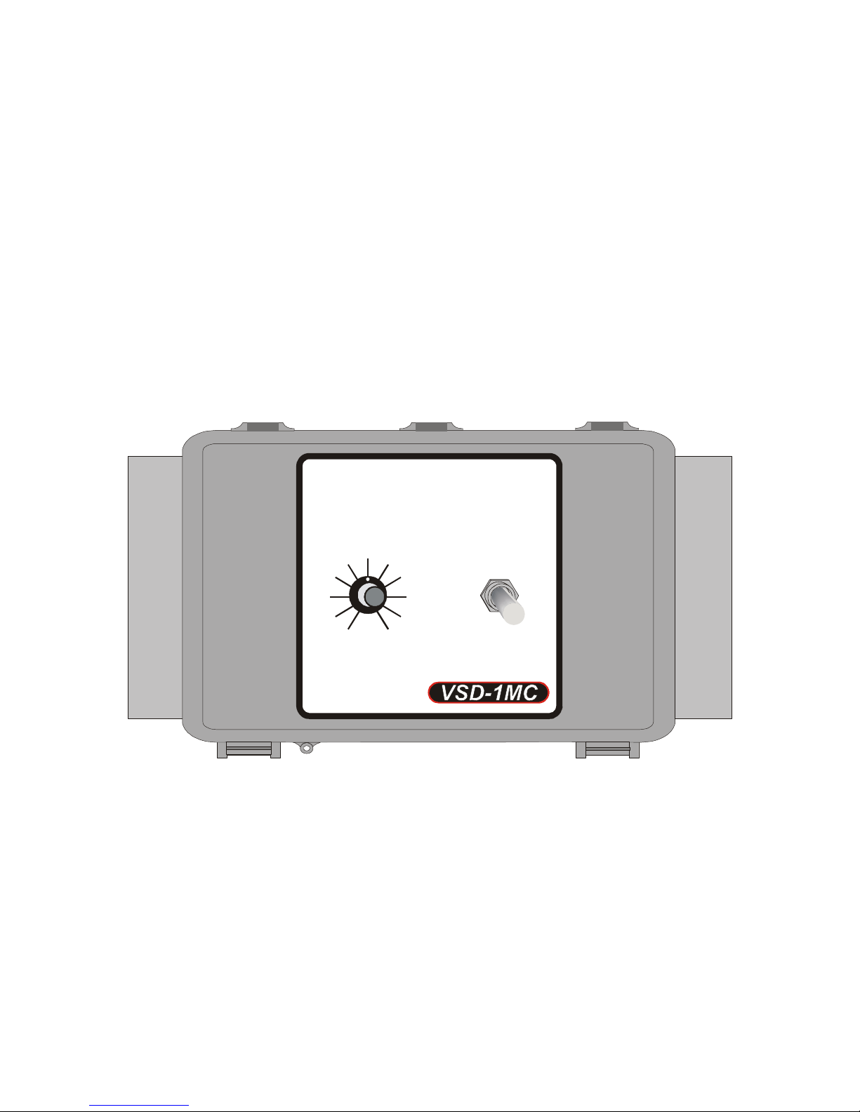
VSD-1MC-20(40)
Page 3
General installation guidelines
-It is recommended to install the unit in a hallway to limit the VSD-1MC-20(40)
exposure to noxious gases.
-In order to avoid condensation problems inside the VSD-1MC-20(40), it is
recommended to install the module on an inside wall. If it is not possible, use
spacers to have an air gap between the wall and the module.
-The VSD-1MC-20(40) should be installed in easy-access location but away from
damaging elements (heat, cold, water, direct sunlight…).
-Do not drill the face, the side, the top or the underside of the module.
-Do not install the VSD-1MC-20(40) near high-voltage equipment, power supply or
transformer.
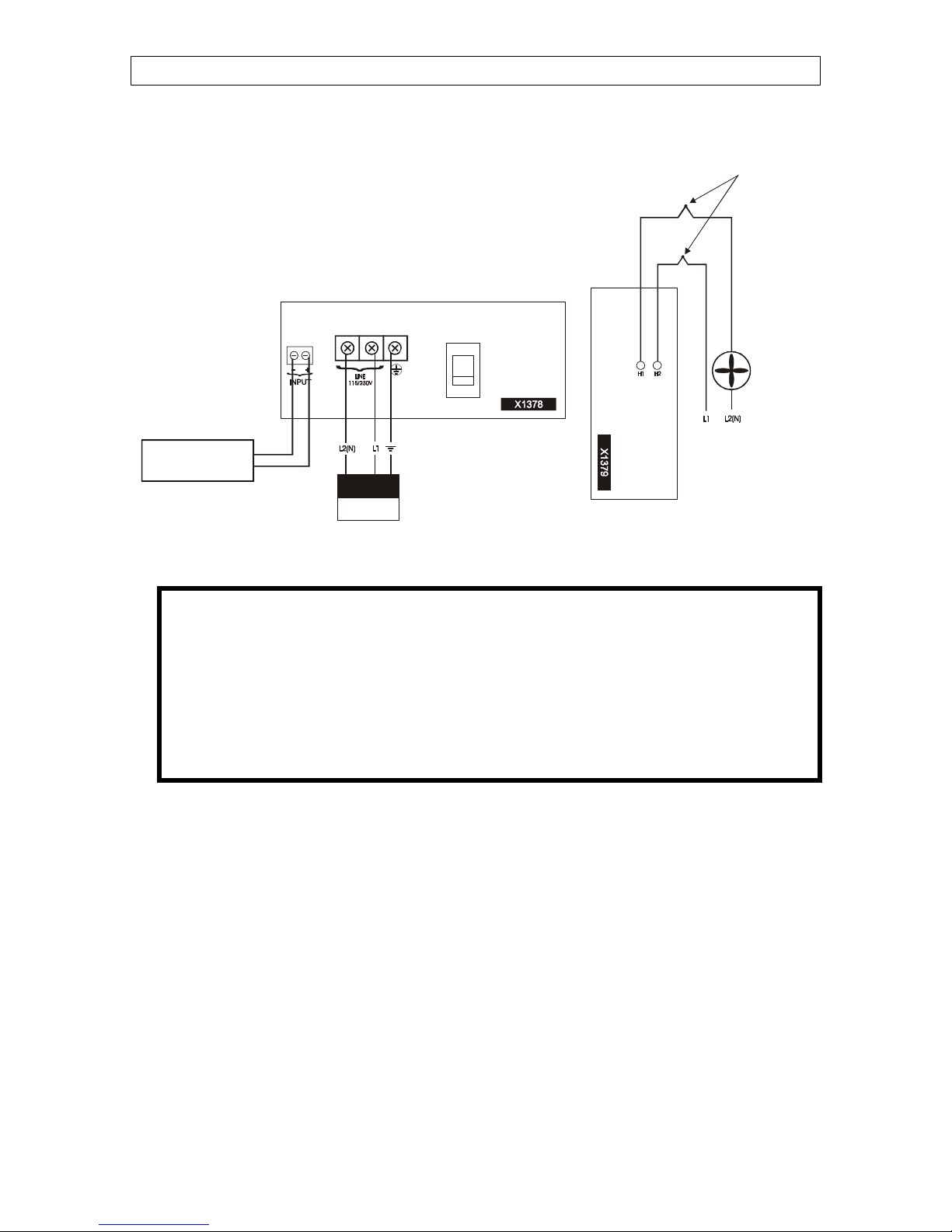
Wiring Procedure
1. Open the VSD-1MC-20(40) module enclosure.
2. Verify the technical specifications to know which wire to use.
3. Connect the equipment to the 2 wires identified as H1 and H2 as shown in figure
1.
IMPORTANT: The variable output requires the same phase and same voltage as the
controller to operate.
4. Connect the power source to the 2 black terminal block identified as LINE as
shown in figure 1.
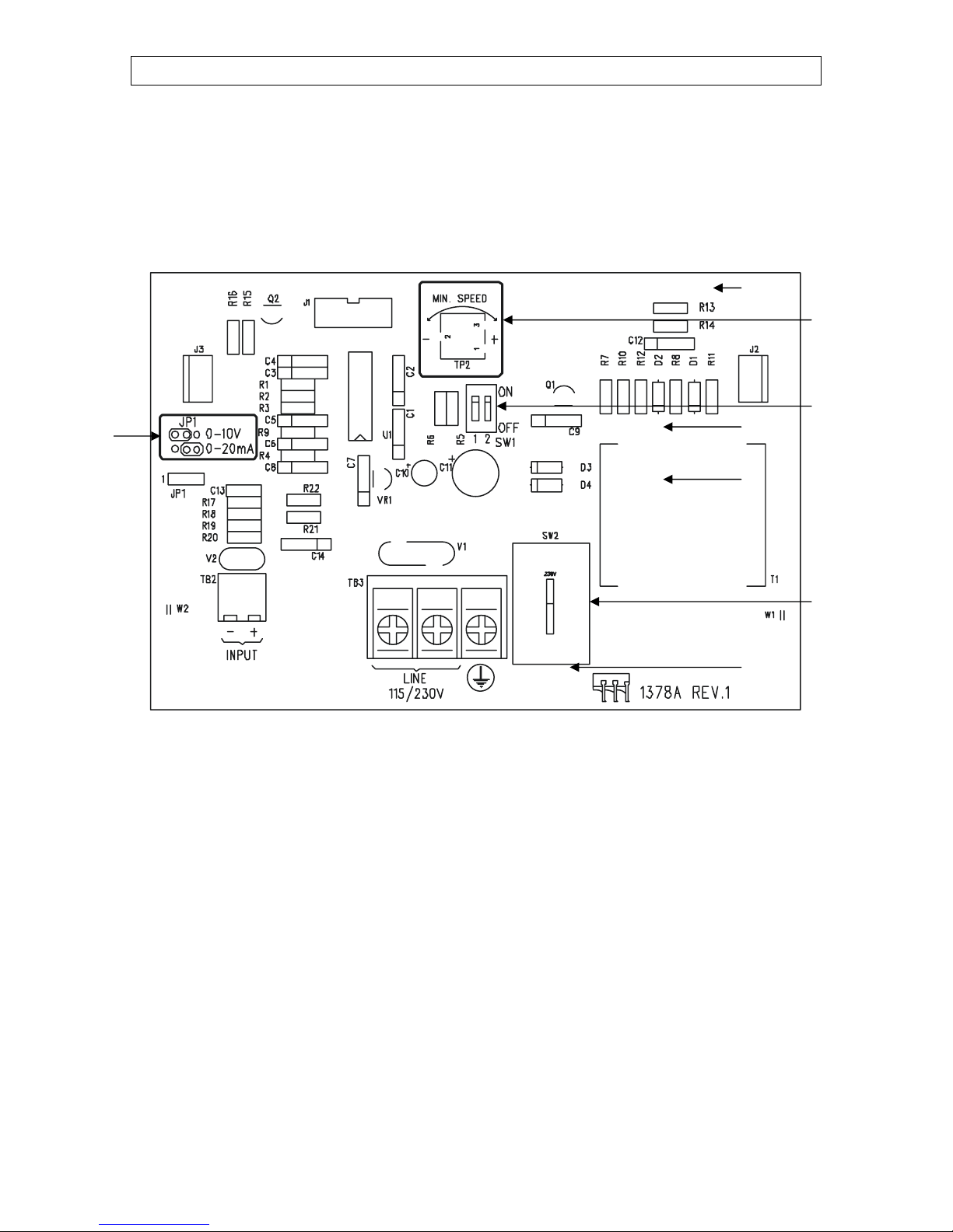
5. Set the JP1 jumper (refer to figure 2 for the location of the jumper) to determine
the correct input type. The two types of input are: 0-20 mA (jumper on the 2 left
pins) and 0-10 Volts (jumper on the 2 right pins).
6. Connect the 0-10 V or the 4-20 mA signal to the 2 green terminal block identified
as INPUT as shown in figure 1.
IMPORTANT: Low-voltage and high-voltage wire must be passed through different
conducts at least 1 foot (30 cm) apart. If low-voltage and high-voltage conduits must
be crossed, the crossing must be at a 90-degree angle.
7. Make sure that the Voltage Selector Switch is set to the correct voltage before
powering up the VSD-1MC-20(40) (refer to figure 2 for the location of the
Voltage Selector Switch).
8. Power up the VSD-1MC-20(40) module. Verify that the module operates
correctly.
9. Close the VSD-1MC-20(40) enclosure. Don’t forget to put a security screw or a
padlock.