8Värmebaronen EK 13
Operation and maintenance
After installation, check with the installer that the system is in
perfect condition.
Ask the installer to demonstrate the control and functions so
that you know how the system should work and be maintained.
Check that:
- No tools have been left in the cartridge's connection space.
- The electric cartridge and the heating system have been filled
with water and vented.
Air may remain for a while, for which reason a few more checks
should be made.
- Pipe connections are leakproof.
- Safety valves work. Water must enter the blow-off pipe when
the valve is operated.
- Start the electric cartridge by switching the main switch to
position 1.
Set the thermostats to the required temperature.
As the cartridge has been without power, the connection delay will
limit the power connection for the first two hours.
- The circulation pump works and has the right speed.
- Heat is distributed to the radiator system.
- The temperature matches the temperature selected. It may take
a while before the temperature in the system has been stabilised.
Control panel
5
8
6
10
17
11
16
7
15
5. Main switch.
6. Operation indicator.
7. Miniature circuit breaker.
8. Reset overheating protection.
10. Thermostat for power stage one.
11. Indicator for power stage one.
15. Indicator for power stage two.
16. Indicator for power stage three.
17. Thermostat, power stages two and three.
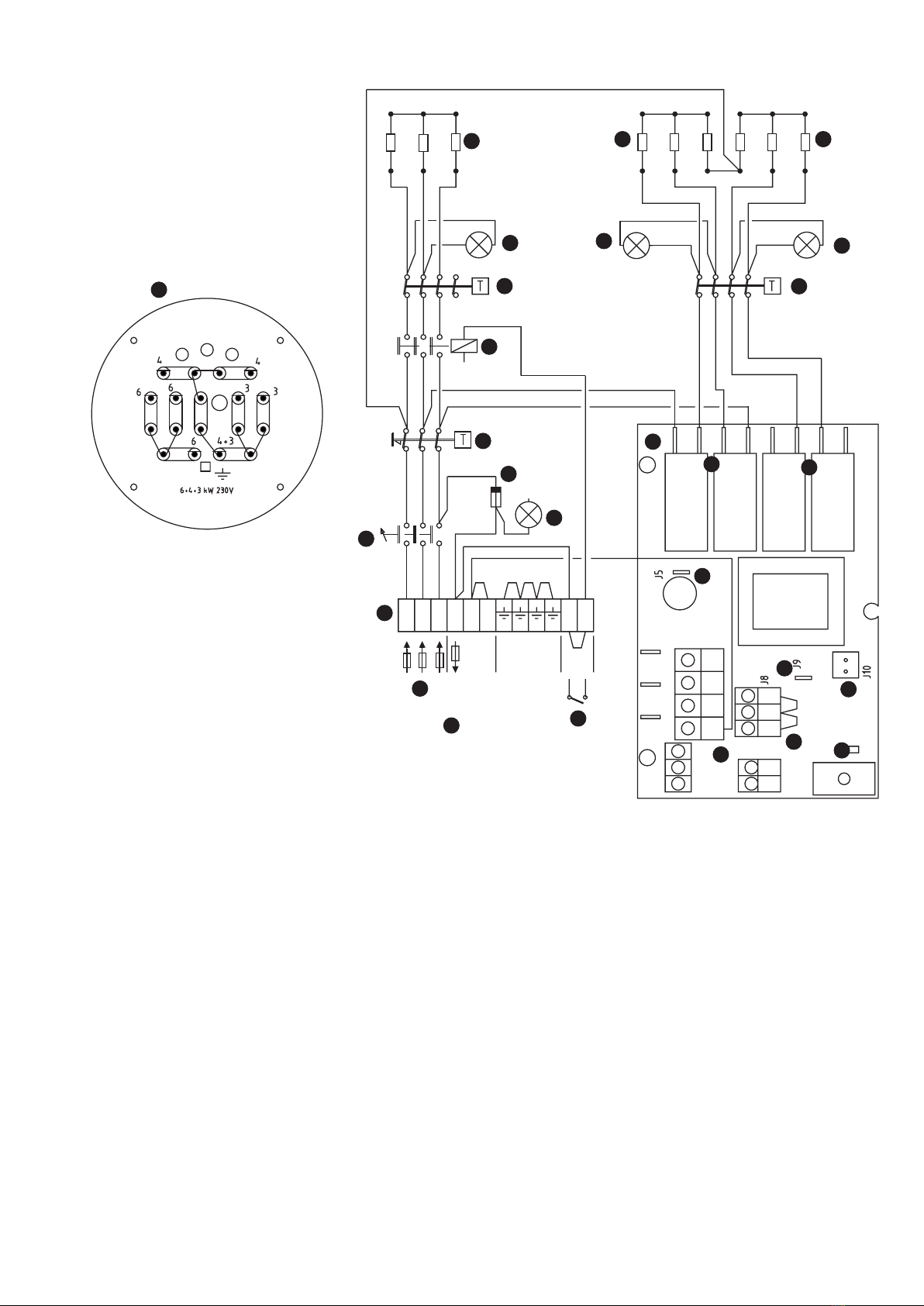
Operation
The electric power is controlled by two thermostats. The thermo-
stats have a difference of approximately 5 °C between breaking
and closing. This means that if the thermostat is set to 65 °C, it
breaks when the temperature reaches this level. The thermostat
closes again when the temperature has fallen to approximately 60
°C.
The thermostat for power stages two and three works in two
stages. Stage two is connected at 5 °C lower than stage three.
Otherwise it works in the same way as the thermostat for power
stage one.
Overheating protection
The electric cartridge has overheating protection that is triggered
when the temperature exceeds approximately 95 °C.
The overheating protection is reset on the side of the electric
cartridge. It may only be reset when the temperature has fallen
below 80 °C. You need to press quite hard to reset the protection.
Venting
Check regularly that there is water in the system. After venting,
the pressure must be checked and water may need to be added.
Action in the event of electrical operation
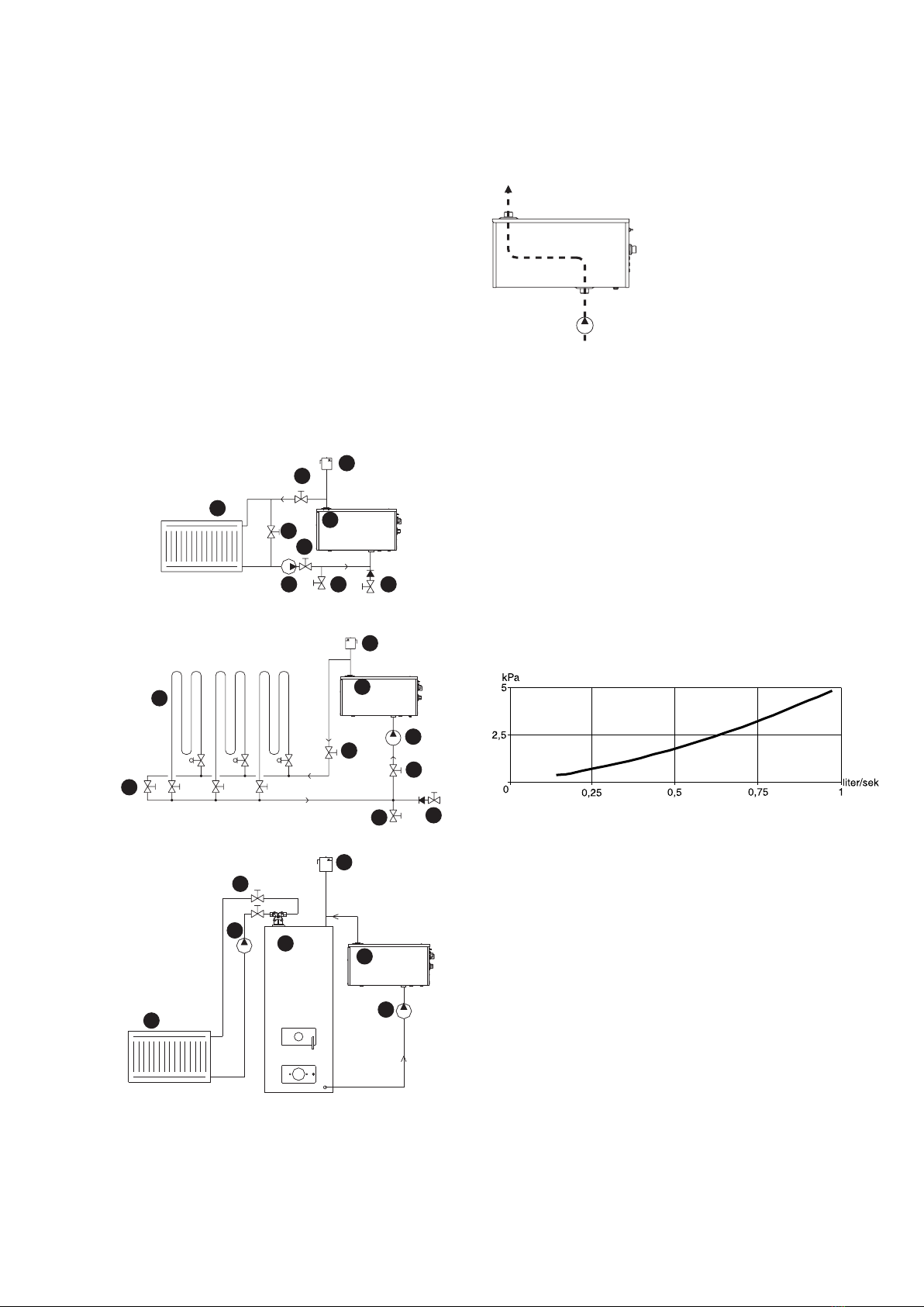
When EK 13 is installed as a supplement to a boiler and the electric
cartridge takes over the heating, any unnecessary air throughput
and thus cooling of the boiler should be avoided.
Safety valve
To maintain safety protection, any safety valve should be operated
regularly, approximately four times a year.
Draining
If the heating system needs to be drained of water, the electric
cartridge must first be switched off so that the immersion heater
is not damaged.
Action in the event of a risk of freezing
When it is extremely cold, no part of the heating system must be
switched off as there is a risk of bursting. If you suspect that any
part of the system is frozen, contact an installation engineer.
If the system is to be switched off for an extended period of time,
the system should be drained or filled with water mixed with glycol.
Frost protection
If the system water is mixed with glycol, it is important for the
glycol to contain a suitable quantity of corrosion-protection agent.
When glycol breaks down, carbonic acid is produced, which
increases the risk of corrosion.
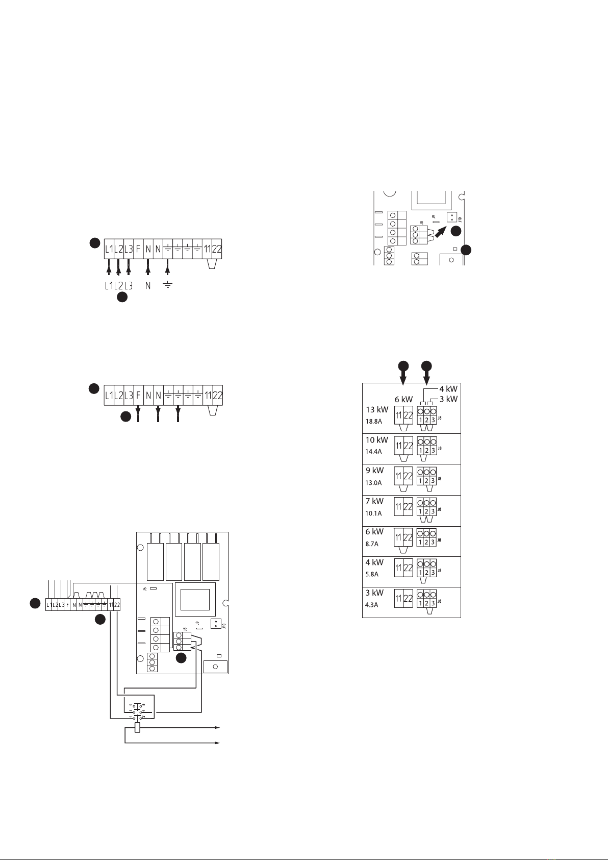
Connection delay
According to the standard, a maximum of 6 kW may be con-
nected directly. The remainder must be delayed for two hours.
This means that, after a power cut that has lasted for longer than
three minutes, only two of the electric cartridge's power stages are
connected directly. The remainder are connected (if required) two
hours after the power has returned.