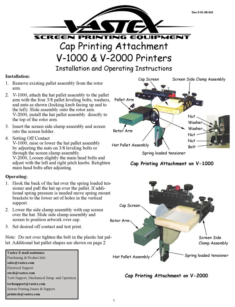
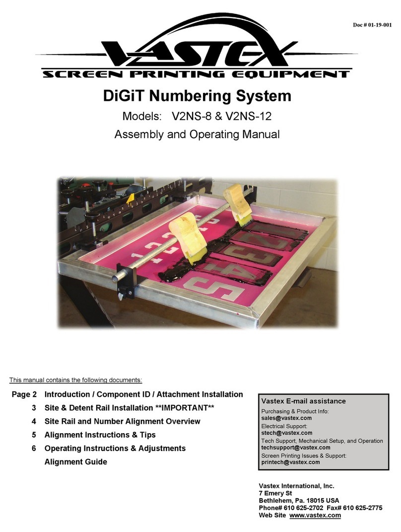
VASTEX DJR-8-U User instructions

DIGIT-JR Numbering System
Assembly and Operating Manual
Vastex International, Inc.
7 Emery Street
Bethlehem, Pa. 18015 USA
Phone# 610 625-2702 Fax# 610 625-2775
Web Site www.vastex.com
Vastex E-mail assistance
Purchasing & Product Info:
Electrical Support:
Tech Support, Mechanical Setup, and Operation
techsupport@vastex.com
Screen Printing Issues & Support:
Models: DJR-8-U / DJR-8
Doc # 01-19-001
Contents Page#
Introduction 2
Component ID 2
Attachment Assembly/Installation 3-6
Site & Detent Rail Installation 7
Site Rail and Number Alignment Overview 8-9
Operating Instructions 10
Adjustments 11
Alignment Guide (AG) 12

The DIGIT-JR was designed and built as light as possible, while still maintaining great strength and durability.
This attachment will clamp into any rear clamp manual press when universal mounting is purchased. The print head
must be able to support a minimum of 11 lbs each. It must also be strong enough to hold the screen level when slid to
the end printing positions. Additional springs or shocks may be required for your press to hold this attachment. Vastex is
not responsible for damages incurred while trying to retrofit our DIGIT-JR to your press. A Vastex V-2000 press
needs no modifications to mount the DIGIT-JR. A V-1000 will need either an HD head upgrade, or a Microless Head
Option. The V-100 will hold the DIGIT-JR in stock form.
There are different Site and Detent Rails for all sizes of numbers. The same Site and Detent rails are used for
all screens of the same height numbers. Detent and Site rails are marked to indicate each size.
Introduction
Component Identification
4” Site Rail
6” Site Rail
8” Site Rail
8” Detent Rail
6” Detent Rail
4” Detent Rail
Clamping
Assembly Roller Assembly
Universal Clamp
Detent RailClamping
Assembly
Site Rail
Clamp
Roller Assembly
Flag
ID Holes
Pg. 2

Attachment Installation (V-100)
1) Loosen and remove (2) Carriage bolts and
5/16-18 nuts to remove screen clamp
-Using 1/2” or 13mm wrench
2) Remove Screen Clamp and set aside.
3) Install Digit-JR Roller Assembly using (2)
Carriage bolts and 5/16-18 nuts removed in
step 1. Use Upper Square cutouts. Flag is
pointing up for reference.
-Tighten Well using 1/2” or 12mm wrench
5/16-18 Nut
Carriage Bolt
Roller Assembly
Screen Clamp
-For Vastex V-100 Press Manufactured Before 10/1/2018
Optional Pitch adjustment (standard after
10/1/2018) should be used on V-100 presses.
If not installed, please install on each head.
1) Loosen and remove (4) 5/16-18, (2) double
nuts, and (2) washers.
-Using 1/2” or 12mm wrench
2) Remove old front/rear pitch bracket and in-
stall new bracket using same hardware.
-Tighten well with 1/2” or 13mm wrench
3) Install slide brackets with thumb screws as
shown. Double Nut
Thumb Screw
Front/Rear pitch
bracket
Slide Bracket
Use Upper
Square Cutouts
Pg. 3

Attachment Installation (V-1000)
1) Remove Stop bar and allow printhead to raise vertical.
2) Remove springs and slide printhead pin out of slot.
3) Set Printhead to the side, springs and stop bar will be
used for Digit-JR installation.
Remove Spring
Remove Spring
Remove Stop Bar
4) Install V1-EX-100 arm with the springs and stop bar removed in
step 1. Springs can be installed in either top or bottom hole posi-
tions. Top position will give additional lift if necessary.
5) Lower arm down onto rotor arm.
6) Install Digit-JR Roller Assembly using suppled (2) carriage bolts
and (2) 5/16-18 nuts as shown below. Use the lower set of
square cutouts for installation. Flag is facing up for reference
-Tighten well with 1/2” or 13mm wrench.
5/16-18 Nut
Carriage Bolt
Roller Assembly
V1-EX-100(arm)
Use Lower
Square Cutouts
Pg. 4

Attachment Installation (Clamp In)
1) Universal Clamp Assembly must be attached to each Roller Assembly
2) Attach Bottom Channel to roller assembly using (3)10-32 button head
bolts and (3)10-32 square nuts. Tighten well with 1/8” Allen wrench.
Note orientation below.
3) Attach Top Channel to Roller Assembly using (3)10-32 button head
bolts and (3) 10-32 Serrated Nuts. Tighten well with 1/8” Allen wrench
and 3/8” open end wrench or socket. Note orientation below.
10-32 Button Head
10-32 Button Head
10-32 Button Head
10-32 Square Nut
10-32
Button Head
10-32
Serrated Nut
10-32
Square Nut
10-32 Button Head
4) Center the Clamp Assembly in your press’ rear clamps
and tighten the clamps. Leave a minimum of
2.5” (6.3CM) between the Clamp Assembly and the
back of your pallet.
Pg. 5

Clamping Assembly Installation
10-32 Button Head
Clamping Rail
Screen Clamp
(Pre-Assembled)
Clamp Carrier
10-32 Serrated Nut
1) Attach Screen Clamps and Clamp Carriers to Clamping Rail using (5) 10-32 x
1/2” button head bolts and (5) 10-32 Serrated nuts for each Screen Clamp
-Tighten well with 1/8” allen wrench and 3/8” open end.
Take note of the hardware orientation. 3 bolts are installed from the
front, 2 are installed from the rear. **This is an important detail**
2) Slide Clamping Assembly into Roller Assembly as shown below.
3) Install Cotter Pin on ends of Clamping Assembly to prevent unintentional removal
of Clamping Assembly
Cotter Pin
(twist to hold)
Pg. 6

Site Rail Target
1) Loosen the two phillips head screws circled in the picture below.
2) Slide the Site Rail into the slots above the clamps
Be sure to install the correct Site and Detent Rails to match the
screen you will be using.
Detent Rail Installation
Note
The Site and Detent Rails can be installed
while the numbering attachment is on the
press. This is shown off the press for in-
structional purposes only.
(The picture above shows the correct
orientation of an installed Detent Rail.)
Detent Rail
3) Site Rails should be labeled from the factory as shown below.
The Site Rail is a visual aid for selecting the desired print location of the numbers.
The Detent Rail controls the location of the number. Five positions are available for each number. This is a very important step.
The grooves in the
Detent Rail engage
into a Roller Bearing,
locking the screen into
position.
1) Loosen the two philips head screws on the Detent Rail. (shown below)
2) Slide the Detent Rail onto the bottom of the Numbering Attachment and
tighten them down well. See photo (bottom right) for visual reference.
Be sure to install the correct Site and Detent Rails to match the
screen you will be using.
Roller Bearing
Important!
Detent rails must be installed as
shown below. Be sure grooves in
rail lock into the roller bearing!
Site Rail Installation
ID HOLES:
The Site and Detent rails have holes
punched in them. These should match.
8” Site/Detent : 3 ID Holes
6” Site/Detent : 2 ID Holes
4” Site/Detent : 1 ID Hole
ID Holes
Pg. 7

30
(A) (B)
51
(C) (D)
19
(E) (F)
(F)
(A)
(B)
(C) (D) (E)
Your Digit-JR attachments are made up of 4 individual attachments and screens.
1 and 0 are present twice in the system. This enables the user to switch screens less in production.
All site and detent rails of each size are the same. See below for examples of printed numbers and
their respective positions on the site rails/attachments.
The #1 and 1# positions are for printing any number with 1. The Digit-JR compensates for the differ-
ence in width of the number 1 by moving the accompanying number closer to center.
Selected # : 2
Site Rail and Number Alignment Overview
Pg. 8

2) Position and attach the
AG on the pallet using a
center line and references
found on the AG.
To align your DiGiT Numbering System, please photocopy the Alignment Guide (AG)
which is the back page of this manual. This page will aid you in aligning your screens.
1) Photocopy (full size) back
page of DiGiT Manual. (AG)
If your screens do not have, or you do not want
to use, the Alignment Marks, you can do the
same procedure with the box outlines on the AG.
3) Lower the screen and slide the attachment to the
center position of the number farthest to the left.
4) Line up and center the round Alignment Mark on the
AG to the oblong Alignment Mark on the screen.
Alignment
Mark
5) Slide the screen to the center position of the number
farthest to the right.
6) Repeat step 4
7) After you have the Alignment Marks lined up on each
screen you are printing with, print a test print.
Good
Good
Bad
Bad
Good Bad
Alignment Instructions & Tips
Pg. 9

Operating Instructions
1) Install the DiGiT-JR numbering attachments.
Pg3-5
2) Install required Site and Detent Rails. Pg 6
3) Clamp in and locate screen. Pg 8
4) Be sure your screen is leveled in both direc-
tions. Set off contact to 3/8” to ensure the
screen locks fully into the Detent Rail.
5) Install (optional) Vastex Squeegee Rest onto
screen.
6) Ink the screens with athletic ink. For athletic
numbering tips, see document (01-08-028)
found at Vastex.com or contact Vastex Sales
department.
7) Use squeegees cut to proper width. See chart
for sizes.
8) Tilt the screen slightly to slide to the required
number. Print position and sliding position are
shown below.
9) Each number has five printing positions. (Pg 3)
Align the Site Rail to the Target for the desired
printing location. When the screen is in the print
position, the detent will engage into the roller
bearing. A properly set off contact is required for
this to function correctly.
10) To raise the print head, center the screen and
gently lift.
11) Do not lean on number screens. Damage to the
mechanism can occur and off contact will suffer.
Sliding position
Print position
Font
Height Digit Squeegee
Width Font
Height Digit Squeegee
Width
2” 0,2-9 1 1/2”
6” 0,2-9 3 3/4”
1 1 1/4” 1 2 3/4”
4” 0,2-9 2 3/4”
8” 0,2-9 5”
1 2” 1 3 1/2”
Recommended Squeegee Widths
Pg. 10

Adjustments
Assembly is too tight or too loose when sliding left to right?
-Tighten or Loosen Vertical Adjustment bolt and nut.
Loosen if slide is too tight, Tighten if slide is too loose.
Screen tilted down too much in print position?
-Washer(s) must be added behind the UPPER wheel. A 1/4”
washer should be added between the upper wheel and the
Roller Wrap.
Clamps Loose?
-Tighten bolts that hold clamp to clamping assembly. Tighten
well using a 3/8” open end wrench and 1/8” allen wrench.
Detent Rail
Clamp Bolts/Nuts
Add 1/4” washer to adjust pitch
Upper Wheel
Universal Clamp
(Optional)
Vertical Adjustment Bolt
Vertical Adjustment Nut
Pg. 11

This manual suits for next models
1
Table of contents
Other VASTEX Printer manuals

VASTEX
VASTEX V-100 User manual

VASTEX
VASTEX Autoflash User manual

VASTEX
VASTEX V-1000 User manual

VASTEX
VASTEX E-1000 Parts list manual

VASTEX
VASTEX DiGiT V2NS-8 User instructions

VASTEX
VASTEX V-1000 Installation and operating instructions

VASTEX
VASTEX E20-2024 Parts list manual

VASTEX
VASTEX VDC-513610 User manual