manuals.online logo
Brands
  1. Home
  2. •
  3. Brands
  4. •
  5. VASTEX
  6. •
  7. Printer
  8. •
  9. VASTEX E-1000 Parts list manual

VASTEX E-1000 Parts list manual

This manual suits for next models

5

Other VASTEX Printer manuals

VASTEX E20-2024 Parts list manual

VASTEX

VASTEX E20-2024 Parts list manual

VASTEX VDC-513610 User manual

VASTEX

VASTEX VDC-513610 User manual

VASTEX DJR-8-U User instructions

VASTEX

VASTEX DJR-8-U User instructions

VASTEX DiGiT V2NS-8 User instructions

VASTEX

VASTEX DiGiT V2NS-8 User instructions

VASTEX V-1000 User manual

VASTEX

VASTEX V-1000 User manual

VASTEX Autoflash User manual

VASTEX

VASTEX Autoflash User manual

VASTEX V-1000 Installation and operating instructions

VASTEX

VASTEX V-1000 Installation and operating instructions

VASTEX V-100 User manual

VASTEX

VASTEX V-100 User manual

Popular Printer manuals by other brands

Evolis Elypso user guide

Evolis

Evolis Elypso user guide

Lexmark 522n - C Color Laser Printer Service manual

Lexmark

Lexmark 522n - C Color Laser Printer Service manual

Panduit COUGAR LS9Q Operator's manual

Panduit

Panduit COUGAR LS9Q Operator's manual

Olivetti PG L2140 Operation guide

Olivetti

Olivetti PG L2140 Operation guide

Samsung SL-M2820DW user manual

Samsung

Samsung SL-M2820DW user manual

Kyocera FS-9530DN specification

Kyocera

Kyocera FS-9530DN specification

Canon LASER SHOT LBP-1210 Specifications

Canon

Canon LASER SHOT LBP-1210 Specifications

Canon PIXMA PRO-1 Series Getting started

Canon

Canon PIXMA PRO-1 Series Getting started

Canon LBP113w Getting started

Canon

Canon LBP113w Getting started

Lexmark Infoprint 1332 user manual

Lexmark

Lexmark Infoprint 1332 user manual

Epson M1120 user guide

Epson

Epson M1120 user guide

TransAct POSJET 1500 Spare parts

TransAct

TransAct POSJET 1500 Spare parts

Telpar MTP-1500 user manual

Telpar

Telpar MTP-1500 user manual

Star DP8340 SERIES user manual

Star

Star DP8340 SERIES user manual

MGI JETVARNISH 3DS user manual

MGI

MGI JETVARNISH 3DS user manual

Kyocera TASKalfa PA4500ci Operation guide

Kyocera

Kyocera TASKalfa PA4500ci Operation guide

Emaar EP-360 user manual

Emaar

Emaar EP-360 user manual

Fujitsu DL7400 user manual

Fujitsu

Fujitsu DL7400 user manual

manuals.online logo
manuals.online logoBrands
  • About & Mission
  • Contact us
  • Privacy Policy
  • Terms and Conditions

Copyright 2025 Manuals.Online. All Rights Reserved.

Doc. # 01-04-033A
Vastex International, Inc.
7 Emery St
Bethlehem, Pa. 18015 USA
Phone# 610 625-2702 Fax# 610 625-2775
Web Site www.vastex.com
Authorized Representative in Europe:
Certification Experts BV
Nieuwstad 100 1381 CE Weesp,
The Netherlands
Tel :+ 31 (0) 294 – 48 33 55
Fax :+ 31 (0) 294 – 41 46 87
Year of Manufacture: 20____ Original Instructions
Serial Number: VTX
(Please log your machine's serial number and date of purchase for future reference.)
Date: //
Electrical Drawing #: Revision:
Vastex E-mail assistance
Purchasing & Product Info:
[email protected]
Electrical Support:
[email protected]
Tech Support, Mechanical Setup, and Operation:
[email protected]
Screen Printing Issues & Support:
[email protected]
E-1000/E-2000 Exposing Units
Assembly and Operation Instructions
Contents Pg. #
•Introduction, Machine Specifications 2
•Safety Information 3
•Assembly Instructions 4-5
•Operating Instructions 6-8
•Maintenance 9
•Troubleshooting 10-12
•Emulsion Tips 13-14
•Warranty/Terms and Conditions 15
E2-2536 E2-5236
Doc. # 01-04-033A
Vastex Exposing Units
(UV Exposure Systems)
Thank you for purchasing your printing equipment form Vastex International Inc.
Vastex has been designing and building printing equipment since 1960. We have knowledge and
experience, and are proud to supply the printing industry with quality equipment at an affordable price. You
can be confident your purchase will give you years of trouble free service.
E2-2536 E2-5236 E1-2536 E1-5236
Overall Size
(lid closed)
Depth x Width x Height
32.75” x 37.75” x 14”
(83 x 88 x 36 cm) 65.3” x 49.3” x 44.5”
(166 x 125 x 113 cm) 32.75” x 37.75” x 14”
(83 x 88 x 36 cm) 65.3” x 49.3” x 44.5”
(166 x 125 x 113 cm)
Weight 210 lbs (95.5 kg) 345 lbs (156.8 kg) 210 lbs (95.5 kg) 345 lbs (156.8 kg)
Screen Capacity 25" x 36" 52” x 36” 25" x 36" 52” x 36”
Power
Requirements
120v: 60Hz @ 3.5 Amps
240v: 50/60Hz @ 2 Amps
120v: 60Hz @ 8 Amps
240v: 50/60Hz @ 4 Amps
120v: 60Hz @ 3.5 Amps
240v: 50/60Hz @ 2 Amps
120v: 60Hz @ 6.5 Amps
240v: 50/60Hz @ 4 Amps
Vacuum Pump
1/4 HP Rocking Piston Pump
(120/240V
P/N: 04-02-060)
1/4 HP Rocking Piston Pump
(120/240V
P/N: 04-02-060)
1/4 HP Rocking Piston Pump
(120/240V
P/N: 04-02-060)
1/4 HP Rocking Piston Pump
(120/240V
P/N: 04-02-060)
Control Board PCB P/N 04-01-135 PCB P/N 04-01-135 PCB P/N 04-01-135 PCB P/N 04-01-135
Glass P/N P/N: 04-08-061 P/N: 04-08-063 P/N: 04-08-061 P/N: 04-08-063
Light Source LED BAR
P/N: 04-08-054
LED BAR
P/N: 04-08-054
UV Black Bulb
P/N: 04-08-062
UV Black Bulb
P/N: 04-08-062
Power Supply P/N: 04-08-055 P/N: 04-08-055 P/N: 04-03-266 P/N: 04-03-266
Vacuum Blanket P/N: EUB-2536 P/N: EUB-5236 P/N: EUB-2536 P/N: EUB-5236
Lid Seal P/N: 04-08-039 P/N: 04-08-039 P/N: 04-08-039 P/N: 04-08-039
Floor Model/
Tabletop Standard: Floor Model Standard: Floor Model Standard: Floor Model Standard: Floor Model
Warranty 3 Years;
Manufacturer Defects
3 Years;
Manufacturer Defects
3 Years;
Manufacturer Defects
3 Years;
Manufacturer Defects
Machine Specifications & Part Numbers
Introduction
Essential Characteristics of tools which may be fitted to this machinery:
This equipment is not designed to be used with any additional attachments or
tools, other than as specifically listed in this manual.
Pg. 2
Doc. # 01-04-033A
** WARNING HANDLE GLASS WITH CARE **
•Wear gloves when handling the glass
•Lay glass only on a flat protected surface
Safety
Intended Use:
This equipment is intended for the purpose of exposing screens and films with UV light in conjunction with
UV sensitive emulsions.
Safety:
• The operator should read and understand this manual before operating this equipment. Store manual
and safety information near equipment for easy
access to operators.
• Never leave equipment unattended while in operation.
• Children and pets must be kept clear of the work area.
• Do not store any objects on top of the exposing unit.
• Unplug power cord before removing glass or entering control box.
• Do not operate if any guard or cover has been removed.
• Do not operate if power cord is damaged.
• Safe Operating Temperature (Ambient): 55°F-100°F (13°C-38°C)
• Do not attempt to defeat safety interlocks.
• Noise and Vibration: This noise level produced by this equipment does not exceed 70 dB(A).
General Information
Tools Required
• Philips Head Screw Driver
• 7/16”, 9/16" & 5/8” Wrenches
• OR METRIC: 11mm, 15mm, 16mm
• Exposing Unit must be on a flat surface to
eliminate stress on the glass.
• Caution! Screens must be free of sharp edges.
All surfaces coming in contact with vacuum
blanket should be rounded and smooth.
• UV Lights are used in this machine. The lights
should Not Be viewed during operation without
eye protection.
• Keep the lid in the raised position when not in
use. It will increase the life of lifting cylinders
and the rubber blanket.
Pg. 3
Doc. # 01-04-033A
Assembly
Getting started:
Your Exposing Unit has been fully assembled and tested in our factory. Both lid lifting cylinders have
been removed from their upper mounting stud and secured to the side of the cabinet. Be careful not to
damage the rubber vacuum blanket when removing the Exposing Unit from it's crating.
It is best to keep the lid locked closed when lifting the exposing unit. Carefully remove the unit from its
crate and place it on a suitable surface. It is important that the surface be flat, an uneven surface can put
stress on the glass causing it to crack.
Placing the equipment into service and operating the equipment:
To place equipment into service, follow steps 1-4 on Page 5
To operate your exposure unit, follow the instructions on Pages 6-8
For troubleshooting and maintenance instructions see pages 9-12.
Stability during use, transportation, assembling, dismantling when out of service, testing, and
foreseeable breakdowns:
This equipment is designed to be stable under all foreseeable conditions if the instructions provided
herein are followed. Do not place the units into positions not shown in this manual (e.g., on their sides) and
do not operate with any parts removed unless necessary for troubleshooting.
Safe transport, handling, storage: when the equipment is transported, it should moved by two or more
people. No other special precautions are required. Refer to page 2 for unit masses.
E2-2536 shown
Components may be located elsewhere on other models.
Control panel
Power cord
Equipment spec tag
Lid limit switch
Vacuum Pump
Vacuum exhaust
(in rear)
(2) Lid lifting
cylinders
Rubber vacuum blanket
(2)Lid locking handle
Rear screen stops, right stop
vacuum intake
(under blanket)
Lid
Exhaust fan
(E2 ONLY)
(2) Legs
Pg. 4
Doc. # 01-04-033A
4) Install Lid Lifting Cylinders
Remove the acorn nut from the upper cylinder
mounting studs located on both sides of the
lid. Unlock and carefully lift lid far enough to
slide lifting cylinders onto studs. Replace
acorn nuts onto stud. Snug only with a 5/8”
wrench. Do not over tighten!
1) Install legs, if included. Place Legs on a clear
spot on the floor, 28.5” (72.5cm) apart as
shown in picture 1.
2) Lock lid handles as shown. Carefully lower the
exposing unit down onto the legs. Two people
are required to do this as caution must be
taken to not damage the machine’s glass or
rubber blanket.
3) Legs are installed with (8) 3/8" bolts and (8)
3/8” serrated nuts. Use (2) 9/16” open end
wrenches and tighten all bolts well.
Assembly Cont’d
Step 1
Step 2
Step 3
Step 5
Pg. 5
Doc. # 01-04-033A
Sequence of Operation
1) Raise the exposing unit lid and wipe the glass
surface clean with a lint free rag.
2) Position the screen with positive attached, onto
the glass and against the two back screen
stops.
Do not position any screen outside screen area
indicated by the blue tape. Damage to vacuum
blanket can result.
3) Lay the small string attached to the rear of the
exposing unit over the edge of the screen to
assist in achieving a good vacuum in the center
of the screen.
4) Lower the lid and lock closed with both
handles.
5) Turn on the power switch.
6) Set the Vacuum Time. (See Touchscreen
Controls).
7) Set Exposure Time. (See Touchscreen
Controls).
8) Start Exposure Cycle. The vacuum pump will
start. After the vacuum timer has reached
preset time the UV lights will start. After the
exposing time has expired, the lights and
vacuum pump will automatically shut off. The
screen is now exposed.
9) Unlock the lid to break the vacuum and remove
the screen.
Tips
Vacuum Time: (for each size screen)
Lock lid and set vacuum time to 90 Seconds. Start
cycle and record the time it takes to flatten the
blanket to a size larger than your positive. If unsure,
wait until blanket is flat to within 2” (5cm) of frame.
Exposure Time:
A full and complete exposure will be effected by
several variables listed by importance.
1) Type and brand of emulsion
2) Thickness of stencil (qty. of coats or capillary
film thickness)
3) Mesh color
4) Humidity
For this reason the only proper way to determine
the correct time for a full and complete exposure is
to use a “Exposure Calculator”. Several types of
calculators are available, contact your supplier to
determine which is best for you.
Approximate setting for single part or “Pure
Photopolymer” is: 10 – 30 seconds. (LED)
Approximate setting for “Dual Cure”: 60 – 300
Seconds. (LED)
Overview:
Your Exposing Unit is equipped with UV Lights, a vacuum pump, and touchscreen controls to digitally
set vacuum and exposure times.
The vacuum pump draws the air out from between the blanket and glass. This flattens the coated
screen and positive to the glass making for a sharper exposed image.
Operation
Power switch Touchscreen
controls
Control panel
Pg. 6
Doc. # 01-04-033A
Operation Cont’d
Touchscreen Controls
Set your exposure cycle by selecting either
ENTER TIME or SELECT PRESET on the home
screen. Your machine has the ability to save
and recall up to 10 presets, storing vacuum and
exposure times. Selecting ENTER TIME by
default will set the vacuum time to 10 seconds
and the exposure time to 10 seconds. These
settings can be changed and saved away in a
preset.
Setting the vacuum time:
1) From the setup screen, press the number
under the label VACUUM.
2) Enter a time from 0-999 seconds.
3) Press DELETE enough times to enter the
desired time.
4) Press ENTER to confirm selection.
Setting the exposure time:
1) From the setup screen press the number
under the label EXPOSURE .
2) Enter a time from 0-999 seconds.
3) Press DELETE enough times to enter the
desired time.
4) Press ENTER to confirm selection.
Running an exposure cycle:
1) From the setup screen, select RUN to start
the exposure cycle.
2) The remaining vacuum and exposing time
are shown on the run screen.
To end the cycle at any time, select
CANCEL. Pressing CANCEL will return to
the setup screen.
3) After completing a cycle, EXPOSURE
COMPLETE will be displayed. Press OK to
return to the setup screen.
Home Screen
Vacuum/Exposure Screen
Setup Screen
Press for vacuum
Press for exposure
Press to run
Press to save
preset
Return to home screen
Run Screen
Pg. 7
Doc. # 01-04-033A
Operation Cont’d
Saving settings as a preset:
1) On the setup screen, select SAVE PRESET.
2) Select a letter to save the preset to.
Settings currently stored to the letter
selected will be shown on the right. Confirm
all settings before overwriting a preset.
3) To cancel saving a preset, press the X in the
upper right corner.
Load Preset Screen
Preset slot Return to home screen
Settings currently
saved in selected
preset
Save Preset Screen
Preset slot Return to setup screen
Settings currently
saved in selected
preset
Error messages:
Your exposing unit could prompt you with several warnings and error messages if triggered.
WAITING FOR CLOSED LID
The lid is in the upright position when Run was selected. Press CANCEL. Lower and lock the lid before
pressing RUN to remove the warning.
EXPOSURE INCOMPLETE: LID WAS OPENED
The lid was opened before the exposure cycle completed. The lid must remain closed for the duration of
the exposure cycle. If the error occurs during the exposing part of the cycle, it is recommended to restart
the exposure with a fresh screen.
EXPOSURE INCOMPLETE: POWER FAILURE
A power failure occurred during an exposure cycle. Loss of power to the unit or from the power supply will
trigger this error. If the error occurs during the exposing part of the cycle, it is recommended to restart the
exposure with a fresh screen.
Loading a saved preset:
1) From the home screen, choose SELECT
PRESET.
2) Select the desired preset.
Settings saved in the preset are shown on
the right side.
3) Select LOAD to load the desired preset.
4) To return to the home screen, select the X in
the upper right corner.
Pg. 8
Doc. # 01-04-033A
Glass Removal / Installation
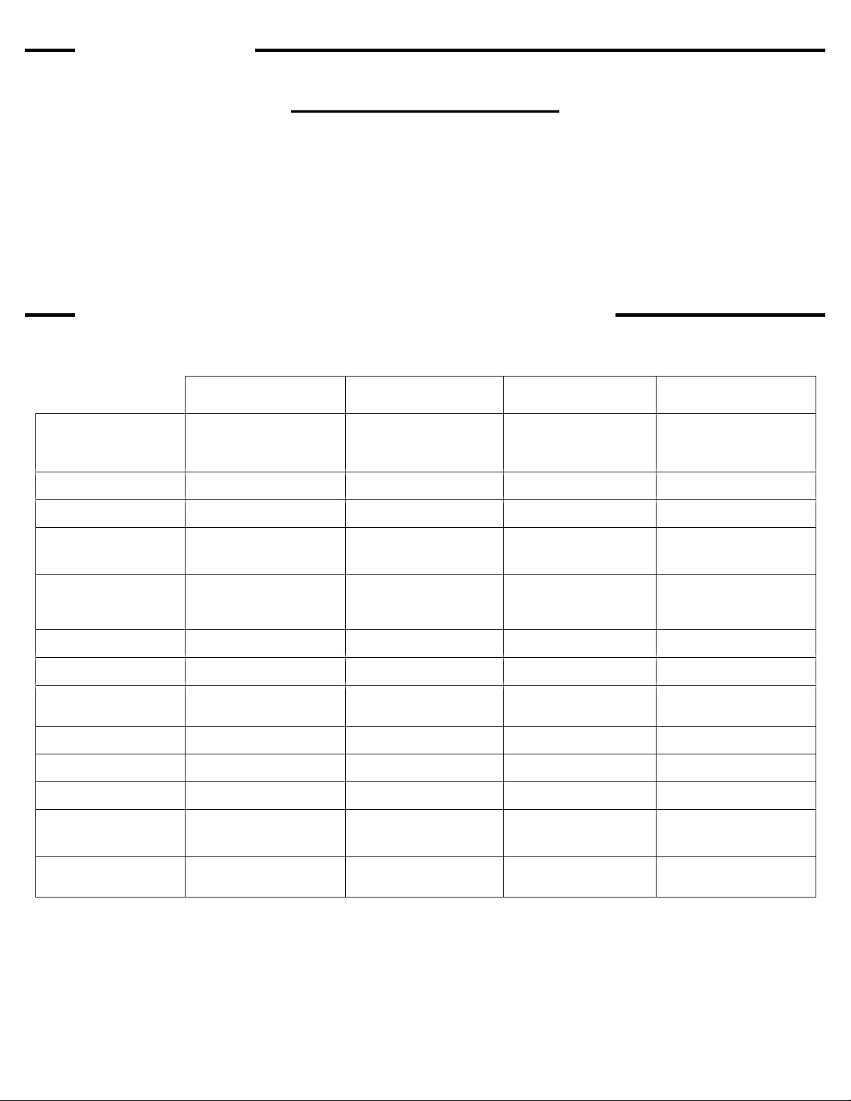
There are three glass retainers. One on each side
to square the glass to the rear seal and one in the
front with special cams. The cams are used to
gently push the glass back against the rear seal.
1) Remove the cams and front retainer. Slide
the glass towards the front to remove.
Carefully set glass on a flat, protected
surface. The cams are used to gently push
the glass back against the rear seal.
2) It is important to keep the inside of the
cabinet clean. Vacuum out any loose debris
from inside the cabinet. Refer to the replacing
a light bar if needed.
3) Reinstalling the glass.
Before installing the glass, switch the vacuum
pump on and off to verify it is functioning
properly. Clean both sides of the glass with
glass cleaner and a lint free rag. Vacuum
inside of cabinet. Position the glass seal side
down, blue tape towards the front, on the
front edge of the cabinet, and between the
side retainers. Slide glass back until it
contacts and it seated squarely against the
back seal. Place the front glass retainer and
the three cams against the glass front. Install
the screws but only snug the screws. Using a
1/4” flat screw driver in the cam slots, rotate
each cam to push the glass back. Do not
over tighten the cams but apply enough
pressure to make a seal. Now tighten the
center screws. If the vacuum leaks, go back
and tighten the cams a bit more.
4) Inspection of LED light bars should be
conducted monthly. See page 11, Step 1,
for instructions.
Inspection of UV Black bulbs should be
conducted bi-monthly. See page 12, Step 1,
for instructions
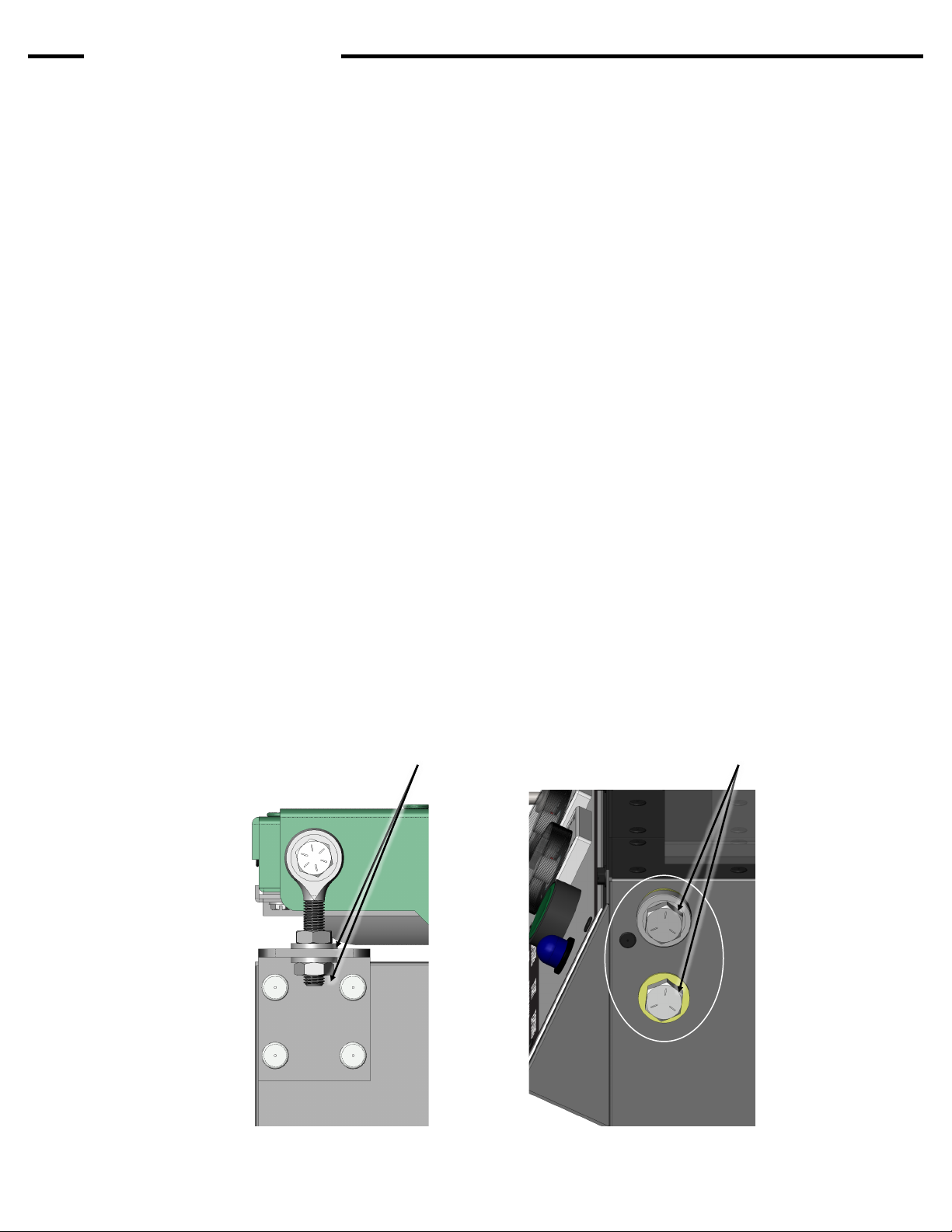
Note: The glass must be tight
against the back glass seal in
order to make a good vacuum.
Special cams help to apply
pressure. Do not over tighten.
Wear gloves when handling the
glass. Glass is tempered and
although strong, can shatter if the
edges are subjected to an impact.
Do Not allow objects to
contact the UV lights.
Maintenance
Side glass
retainer
(1 each side)
Rear glass seal
Front glass retainer,
with 3 cams.
Pg. 9
Doc. # 01-04-033A
1) Verify that vacuum pump is running.
2) Examine the rubber blanket for holes or cuts.
3) Check that the holes in the back left screen stop
is not blocked. Turn on the pump and verify that
there is vacuum through the left stop.
4) Check that the clear tube protruding through left
side of cabinet wall is unobstructed. This is the
vacuum pump exhaust.
5) Verify that the back glass seal is not damaged.
If it is not try tightening the front cams just
slightly. If this does not work, pull the glass away
and inspect the seal, then reseat the glass
squarely against the back seal and retighten the
front cams.
6) There is a foam seal around the perimeter of the
lid between the rubber blanket and lid frame.
With the lid locked down, check that the lid seal
and blanket is contacting the glass at all four
sides. If this seal is not contacting the glass it
will be necessary to adjust the lid lower.
Proceed as follows (pictures below for
reference).
a) Remove both Lid Lifting Cylinders from their
upper mounting stud. Carefully lower the lid.
b) Rear Seal Adjustment. Start with the lid
down and locked. Using a 1/2" wrench,
loosen the top nut 1/2 turn then tighten the
bottom nut 1/2 turn. This will adjust the lid
down .025". Do this to both sides until
vacuum seal is achieved
c) Front Lid Adjustment. Using a 9/16
wrench, loosen (2) bolts at each front corner
about 1/8 of a turn. Using a piece of wood
and a hammer, tap on the top bolt head
slightly to move the bearing down. Be
careful to avoid moving it too much. For
reference, measure from the top of the
bearing to the bottom of the lid when closed,
do not adjust more than 1/16 of an inch.
Retighten all fasteners.
7) Contact Vastex for technical support if these
steps fail to resolve the problem.
Troubleshooting
Rear Lid Adjustment
Rear Lid Adjustment Nuts Loosen 1/8 turn for adjustment
Front Lid Adjustment
(All models)
Loss of Vacuum
This can be caused by several problems. Check the
following items in order listed.
Pg. 10