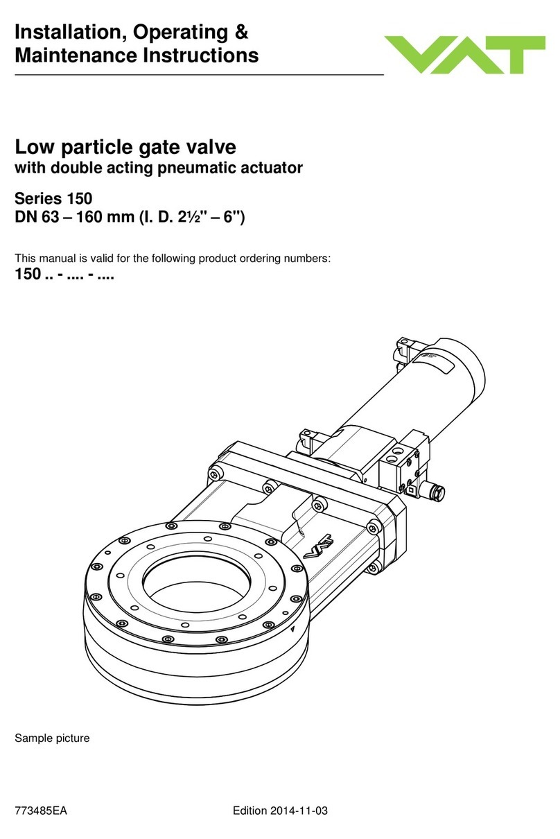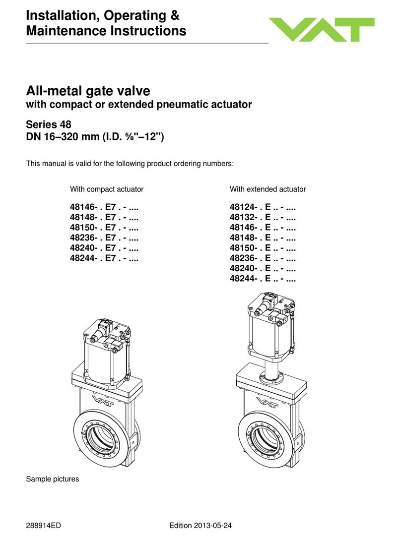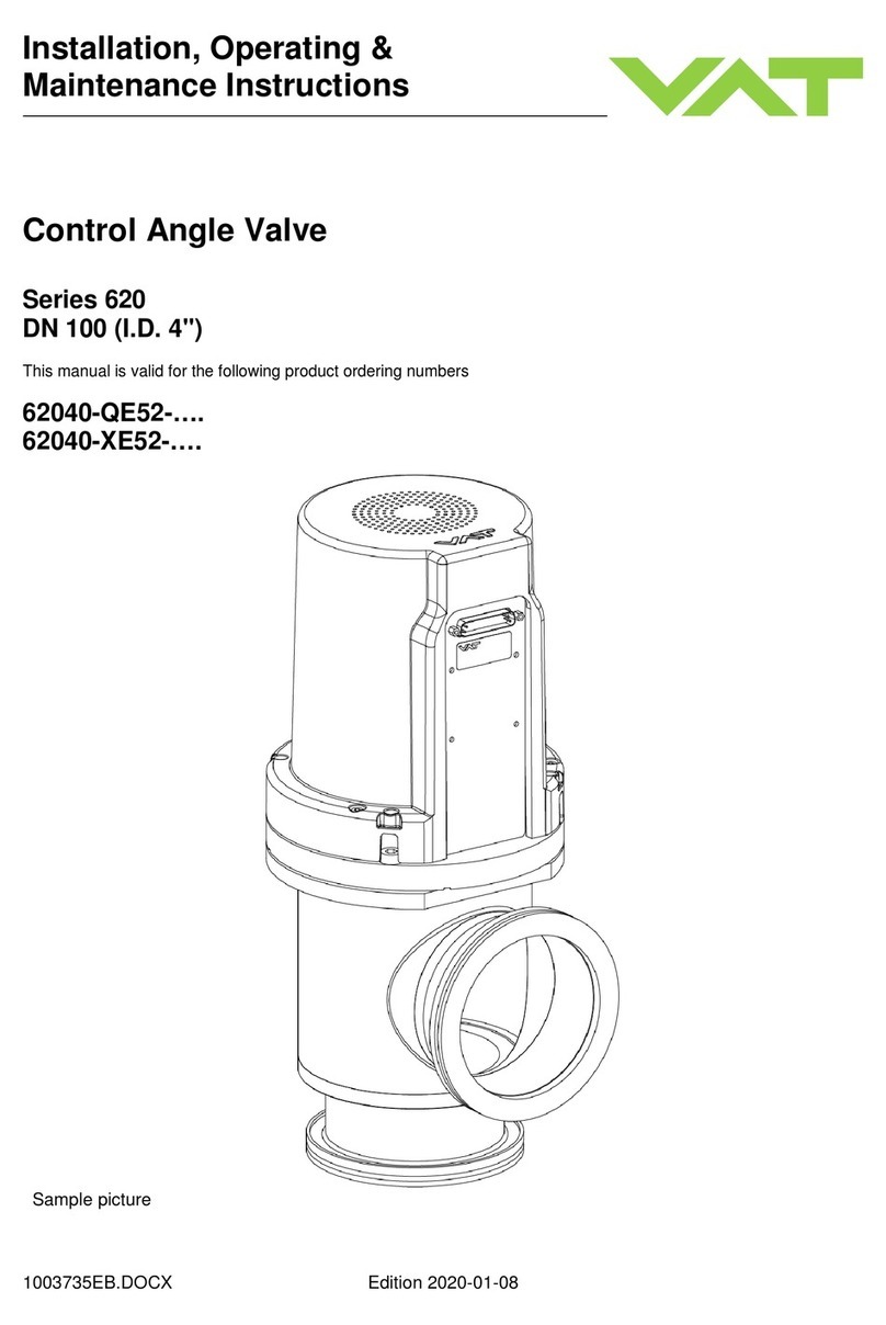
Installation, Operating & Maintenance Instructions
Series 168, DN 400-500 (I.D. 16-20")
VAT Vakuumventile AG, CH-9469 Haag, Switzerland
Tel +41 81 771 61 61 Fax +41 81 771 48 30 CH@vatvalve.com www.vatvalve.com 240763EL
18.05.2009 3/17
Contents:
1Use of product .......................................................................................................................................................... 4
1.1 Technical data.................................................................................................................................................... 4
2Installation................................................................................................................................................................. 5
2.1 Unpacking.......................................................................................................................................................... 5
2.2 Installation into the system................................................................................................................................. 6
2.3 Admissible forces............................................................................................................................................... 6
2.4 Connections....................................................................................................................................................... 7
2.4.1 Compressed air connection..................................................................................................................... 7
2.4.2 Electrical connection................................................................................................................................ 7
3Operation.................................................................................................................................................................. 8
3.1 Normal operation................................................................................................................................................ 8
3.2 Operation under increased temperature............................................................................................................ 8
3.3 Behavior in case of compressed air pressure drop............................................................................................ 8
3.4 Behavior in case of power failure....................................................................................................................... 8
3.5 Emergency operation at power failure ............................................................................................................... 9
4Trouble shooting....................................................................................................................................................... 9
5Maintenance & repairs............................................................................................................................................ 10
5.1 Safety instruction.............................................................................................................................................. 11
5.2 Maintenance procedures.................................................................................................................................. 12
5.2.1 Cleaning and replacing procedure of gate and bonnet seal..................................................................12
5.2.2 Replacement of locking balls................................................................................................................. 13
6Drawing................................................................................................................................................................... 15
6.1 Mechanism Assembly Drawing........................................................................................................................ 16
7Spare parts............................................................................................................................................................. 17
8Warranty................................................................................................................................................................. 17


