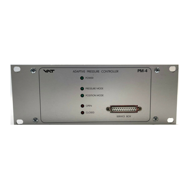
VAT PM-4 User manual

c
e
r
t
i
f
i
e
d
Q
M
-
S
y
s
t
e
m
g
e
p
r
ü
f
t
e
s
Q
M
-
S
y
s
t
e
m
ISO 9001
EN 29001
Installation, Operating, and Maintenance Instructions
Series 64.1
VAT Vakuumventile AG, CH-9469 Haag, Schweiz
Tel ++41 81 771 61 61 Fax ++41 81 771 48 30 Email rec[email protected] http://www.vatvalve.com 225590EE
2005-04-26 1/16
Adaptive Pressure Controller
PM-4 & 5 for Gate Valve Control System
This manual is valid for product with the
product identification number
FABR. NO. 641PM - . 6 . . - . . . .
configured with Software Version
64PM.3I.00
The product identification is specified on the rear panel of each PM controller:
Made in Switzerland in 20 ..
Patented
641P . - . 6 .. - . ... - . . . .
Read these «Installation, Operating and Maintenance Instructions» (IOMI) and the enclosed
«General Safety Instructions» carefully before you start any other action.
Table of content
1 Intended Use of Product..........................................................................................................................2
1.1 Technical Data.................................................................................................................................2
2 Installation...............................................................................................................................................2
2.1 Content of VAT PM Controller Delivery ............................................................................................2
2.2 Hardware Installation .......................................................................................................................2
2.3 PM Configuration (setup sequence) .................................................................................................4
3 Operation................................................................................................................................................5
3.1 Local Mode (PM-4 with Service Box only) ........................................................................................5
3.2 Remote Mode (PM-5 if Interface installed only) ................................................................................5
3.3 Power Failure / Power Failure Option (PFO).....................................................................................5
4 Preventive Maintenance..........................................................................................................................6
5 Spare Parts / Retrofit Options..................................................................................................................7
6 Trouble Shooting.....................................................................................................................................7
7 Repairs....................................................................................................................................................8
8 Warranty .................................................................................................................................................8
9 Engineering Information...........................................................................................................................9
9.1 Wiring of Connectors .......................................................................................................................9
9.2 RS232C Interface Configuration.....................................................................................................12
9.3 RS232C Communication................................................................................................................12
9.4 User Information and Recommendations........................................................................................16
PM-5
PM-4

c
e
r
t
i
f
i
e
d
Q
M
-
S
y
s
t
e
m
g
e
p
r
ü
f
t
e
s
Q
M
-
S
y
s
t
e
m
ISO 9001
EN 29001
Installation, Operating, and Maintenance Instructions
Series 64.1
VAT Vakuumventile AG, CH-9469 Haag, Schweiz
Tel ++41 81 771 61 61 Fax ++41 81 771 48 30 Email rec[email protected] http://www.vatvalve.com 225590EE
2005-04-26 2/16
1 Intended Use of Product
This product is an adaptive pressure controller for VAT series 64 control valves. The product may only be operated within the ranges
specified below:
1.1 Technical Data
Mains voltage 100 - 240 VAC (±10%), 50/60 Hz
Temperature 0 - 50 °C
Sensor input signal 0 - 10 VDC max.
Sensor power supply
+ 15 VDC (±5%), 1400 mA max. (total current for sensor 1 and 2)
- 15 VDC (±5%), 1400 mA max. (total current for sensor 1 and 2)
Operation only with VAT series 64 control valve
Additional technical information see chapter ‚9 Engineering Information‘
2 Installation
2.1 Content of VAT PM Controller Delivery
Adaptive Pressure Controller PM-4 or PM-5
Plug for mains connection of controller
Plug for interface cable
Plug for cable of pressure sensor 1 (standard) and 2 (option)
2.2 Hardware Installation

c
e
r
t
i
f
i
e
d
Q
M
-
S
y
s
t
e
m
g
e
p
r
ü
f
t
e
s
Q
M
-
S
y
s
t
e
m
ISO 9001
EN 29001
Installation, Operating, and Maintenance Instructions
Series 64.1
VAT Vakuumventile AG, CH-9469 Haag, Schweiz
Tel ++41 81 771 61 61 Fax ++41 81 771 48 30 Email rec[email protected] http://www.vatvalve.com 225590EE
2005-04-26 3/16
Confirm that hardware is complete (picture 1)
(1) Adaptive Pressure Controller PM-4 or PM-5, hereafter referred to as PM controller.
For PM controller with power failure option confirm that battery life has not expired (see chapter ‚4 Preventive Maintenance‘)
(2) Connection cable valve - PM controller: VAT part number 640CV-99L .
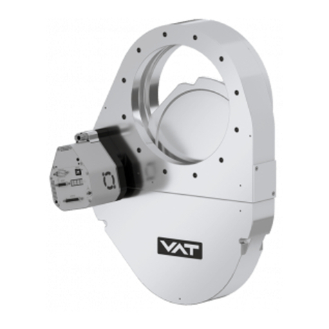
(3) VAT Series 64 control valve
(4) Mains connection, wiring information see chapter ‚9.1.2 Connector for mains‘
(5) Interface cable, wiring information see chapter ‚9.1.3 Connector for interface‘
(6) Sensor 1 (standard) and 2 (option)
(7) Cable for sensor 1 and 2, wiring information see chapter ‚9.1.1 Connector for sensor 1 and sensor 2‘
Install hardware
PM controller must be switched off during installation.
- Install VAT control valve (3) according to the Installation, Operating and Maintenance Instruction Manual of the VAT Series 64 control
valve.
- Install sensor(s) (6) according to the recommendations of the sensor manufacturer
- Install PM controller (1) into control rack.
- Connect valve cable (2) to control valve and then to PM controller (connector: valve)
- Connect sensor cable (7) to sensor(s) and then to PM controller (connector: sensor 1 / sensor 2)
- For remote operation, connect interface cable (5) to PM controller (connector: interface)
- Connect mains cable (4) to PM controller

c
e
r
t
i
f
i
e
d
Q
M
-
S
y
s
t
e
m
g
e
p
r
ü
f
t
e
s
Q
M
-
S
y
s
t
e
m
ISO 9001
EN 29001
Installation, Operating, and Maintenance Instructions
Series 64.1
VAT Vakuumventile AG, CH-9469 Haag, Schweiz
Tel ++41 81 771 61 61 Fax ++41 81 771 48 30 Email rec[email protected] http://www.vatvalve.com 225590EE
2005-04-26 4/16
2.3 PM Configuration (setup sequence)
STEP LOCAL MODE (PM-4 in combination with
Service Box only) REMOTE MODE (PM-5 if interface installed
only)
1 POWER ON 1. PM controller: Turn on power switch at the rear panel of the PM controller. Note: Valve will close, if not in
closed position
2. On PM-5 or Service Box start-up display (Software version, type of interface, etc.) appears, until valve is in
closed position
3. CLOSE(D) is displayed, otherwise please refer to chapter ‘6 Trouble Shooting’.
2 SELECT
MODE Select LOCAL operation by pressing «LOCAL» key for 2
seconds. Select REMOTE operation by pressing «REMOTE» key
on front panel or Service Box for 2 seconds or select
remote operation through RS232 (see ‚9.3.1 Control
commands’) or logic interface (see ‚9.1.3.1 Logic
interface‘)
3 AUTOMATIC
SIZE
ADJUSTMENT
Press simultaneously «OPEN» and «CLOSE» keys for 2
seconds. The controller will perform an automatic size
adjustment procedure to determine open and closed
position and the range between the two positions.
Send RS232 command:
J:<CR><LF> (see ‚9.3.1 Control commands’)
or use Logic command (see ‚9.1.3.1 Logic interface‘)
4 SENSOR
SETUP1) Press simultaneously «LEARN» and «ZERO» key for 2
seconds (notation used hereafter: «&», e.g. «LEARN» &
«ZERO»). Then, use «↑» and «↓» key to change
parameters (VOLTAGE RANGE; DISPLAY RANGE;
DISPLAY UNIT; GAIN FACTOR; SENSOR TYPE; ZERO
ADJUST) for each sensor. Toggle with «F1» key to the
next setup parameter. Press «F2» , when finished.
See ‚9.3.3 Sensor setup command‘
Example:
Sensor 1, Voltage Range: 0-10V; Display Range: 0-10;
Display Unit: Torr; Gain Factor: 1; Sensor Type: Torr;
Zero Adjust: enabled;
s:1332010<CR><LF>
Mind: Not possible to do by a logic interface.
5 ZERO ADJUST
(Offset
compensation of
sensor output)
Evacuate process chamber to high vacuum. When the
base pressure is reached, press «ZERO» key for 2
seconds to reset the offset of the pressure sensor.
Disable ZERO function in SENSOR SETUP, if the base
pressure of your system is higher than 1‰ of sensor full
scale.
Evacuate process chamber to high vacuum. When the
base pressure is reached send RS232 command:
Z:<CR><LF> (see ‚9.3.1 Control commands’)
or use Logic command (see ‚9.1.3.1 Logic interface‘).
Disable ZERO function in SENSOR SETUP, if the base
pressure of your system is higher than 1‰ of sensor full
scale.
6 LEARN 2)
(Determination of
control
characteristics of
your process
chamber)
Process chamber at high vacuum, control valve is open:
Open gas inlet and set gas flow (see recommendation
below). Press «LEARN» key for 3 seconds to perform
the autolearning routine of the PM controller. The
autolearning routine may take several minutes and can
be aborted by pressing the «F1» key. A single full run of
the autolearning routine is required to ensure fast and
accurate pressure control.
Note: It is not necessary to repeat LEARN, if the
sensor setup is changed, or if the second
sensor is selected for pressure control. The
controller covers 5% to 5000% of the gasflow
which was used at LEARN.
Process chamber at high vacuum, control valve is open:
Open gas inlet and set gas flow (see recommendation
below). Then send RS232 LEARN command:
L:001000<CR><LF> (‚9.3.1 Control commands’)
or Logic command (see ‚9.1.3.1 Logic interface‘).
The autolearning routine may take several minutes. A
single full run of the autolearning routine is required to
ensure fast and accurate pressure control.
Note: It is not necessary to repeat LEARN, if the
sensor setup is changed, or if the second
sensor is selected for pressure control. The
controller covers 5% to 5000% of the gasflow
which was used at LEARN.
Legend:
1) The default GAIN FACTOR is 1.00. See chapter ‚9.3.3 Sensor setup command‘ if resetting is necessary.
gain factor > 1 means: faster control but higher overshoot of pressure
gain factor < 1 means: slower control but lower overshoot of pressure
Just 98% of sensor pressure range can be used during control.
If no sensor is used, select as display parameter ‘POS’.
2) Ideal gasflow for autolearning
Q = 40 •pSFS •Lmin
Q...........gasflow for autolearning [sccm]
pSFS.......sensor full scale pressure [Torr]
Lmin ........min. controllable conductance [l/s]
Do not use a different gasflow than
recommended for autolearning otherwise
pressure control performance may be insufficient.
valve size DN63 DN100 DN160 DN200 DN250 DN320 DN400
min. controllable conductance 0.6 l/s 1 l/s 1.6 l/s 2 l/s 2.5 l/s 3.2 l/s 4 l/s

c
e
r
t
i
f
i
e
d
Q
M
-
S
y
s
t
e
m
g
e
p
r
ü
f
t
e
s
Q
M
-
S
y
s
t
e
m
ISO 9001
EN 29001
Installation, Operating, and Maintenance Instructions
Series 64.1
VAT Vakuumventile AG, CH-9469 Haag, Schweiz
Tel ++41 81 771 61 61 Fax ++41 81 771 48 30 Email rec[email protected] http://www.vatvalve.com 225590EE
2005-04-26 5/16
3 Operation
For user information and recommendations for pressure control please refer to ch0r ‘9.4 User Information and Recommendations’
Display Information: (PM-4 with Service Box only)
‘P1:’/’P2:’ for actual pressure, ‘SP:’ for set point pressure, ‘Pos:’ for valve position (0000 = closed, 1000 = open)
Errors:
‘E’ on display for position error, ‘P‘ for parameter error (refer to section ‘6 Trouble Shooting’)
Power-fail option:
‘D’, if power-fail option disabled temporarily (only in local mode possible)
Logic Inputs:
‘M’, if Logic Inputs disabled by RS232C command
3.1 Local Mode (PM-4 with Service Box only)
Activate keyboard:
Press «LOCAL» key for 2 seconds to enable keyboard. LED on «LOCAL» key will turn green.
Open valve:
Press «OPEN». LED on «OPEN» key will turn green.
Close valve:
Press «CLOSE». LED on «CLOSE» key will turn green.
Select sensor: (for double sensor version)
Press «F2» & «↑» key to toggle between sensor 1 and sensor 2. As an alternative, the sensor setup may be used to select the sensor for
pressure control.
Pressure control:
Press «PRESSURE MODE» key, then press one of the four «SET POINT» keys. Use «↑» or «↓» key to change set point value. Store the
set point value by pressing one of the four «SET POINT» keys for at least 2 seconds.
Freeze valve position, interrupt pressure control:
While in PRESSURE MODE, press «F1» key to interrupt pressure control and freeze the actual valve position. ‘HOLD’ will appear on
display. Press «PRESSURE MODE» key to continue pressure control.
Valve position control:
Press «POSITION MODE», then press one of the four «SET POINT» keys. Use «↑» or «↓» key to change the position value. Store set
point value by pressing «SET POINT» key for at least 2 seconds.
Note: Commands «ZERO», «LOCAL», «REMOTE», «LEARN», «F1» & «F2» require that the keys are pressed for 2 seconds, before
the commands are accepted to prevent that the settings are changed accidentally.
Contrast of the display can be adjusted by pressing «F1» & «F2» & «↑», or «F1» & «F2» & «↓» key.
3.2 Remote Mode (PM-5 if Interface installed only)
Press «REMOTE» key for 2 seconds or select remote operation through RS 232C or LOGIC interface for remote control. For details about
interface wiring and remote commands refer to chapter ‘9 Engineering Information’.
3.3 Power Failure / Power Failure Option (PFO)
All parameters will remain stored during a power failure.
If a power-fail battery is installed (check VAT part number of PM controller: 641PM- . 6B . - . . . .), the PM controller has to be hooked up to
power for at least 10 hours to assure repeated valve closures in case of a power failure.
Note: By pressing the «F2» key for 2 seconds, the Power Fail Option will be disabled for 1 minute. A ‘D’ will be displayed on the
control panel.

c
e
r
t
i
f
i
e
d
Q
M
-
S
y
s
t
e
m
g
e
p
r
ü
f
t
e
s
Q
M
-
S
y
s
t
e
m
ISO 9001
EN 29001
Installation, Operating, and Maintenance Instructions
Series 64.1
VAT Vakuumventile AG, CH-9469 Haag, Schweiz
Tel ++41 81 771 61 61 Fax ++41 81 771 48 30 Email rec[email protected] http://www.vatvalve.com 225590EE
2005-04-26 6/16
4 Preventive Maintenance
ESD Precaution!
All work on the controller has to be done under ESD protected environment to prevent electronic
components from damage!
SRAM (see chapter ‚5 Spare Parts / Retrofit Options‘ part number.)
When the battery life expires (typical lifetime is 5 years, check date specified on label on the rear panel of PM controller), the SRAM
memory needs to be exchanged.
Procedure:
- Turn off power to PM controller, disconnect powe
r cable and wait for
60 seconds.
- Disconnect sensor cable, valve cable and interface cable.
- Open top cover of PM controller.
- Exchange SRAM (IC3 on master board), confirm SRAM is installed correctly.
Check mark for pin 1 [{] on SRAM. First row of socket contacts must be left
empty.
- Reattach cover.
- Attach label with new expiration date on back panel of PM controller.
- Perform PM configuration routine
(SENSOR SETUP, AUTO SIZE ADJUST, ZERO, LEARN).
IC3
SRAM (IC3) Socket
Power-fail battery
(this is an option which is installed if controller part-no. is 641PM- . 6B. - ...., see chapter ‚5 Spare Parts / Retrofit Options‘ part number.)
When the PFO battery life expires, PFO battery needs to be exchanged. Production date is specified on label on the rear panel of PM
controller. Life time of NiCd-battery is specified with 20'000 hours if surrounding temperature is not higher than 30°C . A significant
decrease is directly linked with higher temperatures. The following diagram shows the influence on life time at various ambient
temperatures.
PFO duration of life
0
10
20
30
40
50
20° 25° 30° 35° 40° 45° 50°
Environment temperature [°C]
Exp. of life
[month]
PM-4, PM-5
Procedure:
-Turn off power to PM controller, disconnect power cable and wait for 60 seconds
-Disconnect sensor cable, valve cable and interface cable
-Open bottom and top covers
-Disconnect connector J5 of battery pack from the bottom side
-Remove the battery pack from the top side
-Install new battery pack and plug in connector J5 of battery pack
-Reattach covers
-Attach label with new production date on rear panel

c
e
r
t
i
f
i
e
d
Q
M
-
S
y
s
t
e
m
g
e
p
r
ü
f
t
e
s
Q
M
-
S
y
s
t
e
m
ISO 9001
EN 29001
Installation, Operating, and Maintenance Instructions
Series 64.1
VAT Vakuumventile AG, CH-9469 Haag, Schweiz
Tel ++41 81 771 61 61 Fax ++41 81 771 48 30 Email rec[email protected] http://www.vatvalve.com 225590EE
2005-04-26 7/16
5 Spare Parts / Retrofit Options
Description Ordering No.
Preventive maintenance kit for PM controller with power-fail option, consisting of: SRAM, battery pack, label 86705-R1
Preventive maintenance kit for PM controller without power-fail option, consisting of: SRAM, label 86706-R1
Battery pack for power-fail option, for retrofit 67786-R1
LOGIC interface 207806
RS232C interface 75944-R1
Service Box for PM-4 600BS-29NN
6 Trouble Shooting
Problem Recommendation
Front panel:
LED’s and LCD display inactive - Check, if mains switch is on, mains cable is connected, mains supply is on
- Check fuses at rear panel of PM controller
Control does not respond to keyboard
commands - Control in REMOTE, switch PM controller to LOCAL
No or weak text on LCD display - Adjust brightness; «F1» & «F2» & «↑» key
‘PAR:ER’ or flashing ‘P’ displayed
- New auto learning should be performed
- If error occurs after new auto learning and power disruption, replace battery powered
SRAM memory
‘ROM:ER’ displayed - EPROM defective, to be changed
LED on «CLOSE»key is flashing, valve
is closed and does not respond to RS 232
or keyboard commands
- Logic CLOSE input on RS 232 interface is active
Pressure reading is wrong
Negative pressure reading
- Confirm that sensor setup is correct, press «LEARN» & «ZERO»
- When base vacuum is reached and pressure reading is off, perform ZERO command
ZERO command does not work - Valve is not in open position, OPEN valve and bring chamber to high vacuum
- ZERO command is disabled, check sensor setup («LEARN» & «ZERO»)
Display not ‘0’ after ZERO command - Sensor offset voltage is larger than ±1.4V
- System not pumped to base pressure
Pressure control not optimal after LEARN
command - The PM controller reoptimizes the parameters for each set point, repeat pressure
control command after adaption is completed
- ZERO command was not performed before LEARN command
- LEARN command was performed with different gas flow, repeat LEARN sequence
- Make sure sensor range is suited for application (>3% of f.s.)
- Noise on sensor signal, check sensor voltage, make sure a shielded sensor cable is
used
Valve open or in control mode
‘E’ displayed on front panel - Pendulum plate does not reach end position because of mechanical obstruction.
- Check valve installation (torque on valve flange mounting screws too high, see
Installation and Operating Instruction for valve!). Check and clean valve

c
e
r
t
i
f
i
e
d
Q
M
-
S
y
s
t
e
m
g
e
p
r
ü
f
t
e
s
Q
M
-
S
y
s
t
e
m
ISO 9001
EN 29001
Installation, Operating, and Maintenance Instructions
Series 64.1
VAT Vakuumventile AG, CH-9469 Haag, Schweiz
Tel ++41 81 771 61 61 Fax ++41 81 771 48 30 Email rec[email protected] http://www.vatvalve.com 225590EE
2005-04-26 8/16
Problem Recommendation
LOGIC interface installed:
Controller does not respond to logic
inputs
- Switch to «REMOTE»
- Verify that logic Interface is installed correctly
‘LOGIC’ is displayed on front panel during start-up.
LOGIC interface installed:
Controller does not respond to analog
position or pressure setpoint
- One of the 4 setpoints, OPEN or CLOSE digital inputs are activated
RS232C interface installed:
Controller does not respond to
RS 232 commands
- Verify settings of the switch S1 on the RS232C interface are correct
- Confirm that RS232C interface is installed correctly
‘MIXED’ is displayed on the LCD display during start-up
- Confirm that PM controller is in REMOTE
- Logic inputs on RS232C interface override RS232 commands
RS232C interface installed:
Controller responds with error message - Wrong command or transmission error, see chapter ‚9.3 RS232C Communication‘
7 Repairs
Contact VAT for repair. Please check first the fabrication No. 641P . - . . . . . - . . . . - . . . .) marked on the rear panel of the
PM controller. Your VAT representative will discuss with you how the repair can be carried out best.
8 Warranty
Each product sold by VAT Vakuumventile AG (VAT) is warranted to be free from the manufacturing defects that adversely
affect the normal functioning thereof during the one-year period immediately following delivery thereof by VAT, provided
that the same is properly operated under conditions of normal use and that regular, periodic maintenance and service is
performed or replacements made, in accordance with the instructions provided by VAT. The foregoing warranty shall not
apply to any product or component that has been repaired or altered by anyone other than an authorized VAT
representative or that has been subject to improper installation or abuse, misuse, negligence or accident. VAT shall not be
liable for any damage, loss, or expense, whether consequential, special, incidental, direct or otherwise, caused by, arising
out of or connected with the manufacture, delivery (including any delay in or failure to deliver), packaging, storage or use of
any product sold or delivered by VAT shall fail to conform to the foregoing warranty or to the description thereof contained
herein, the purchaser thereof, as its exclusive remedy, shall upon prompt notice to VAT of any such defect or failure and
upon the return of the product, part or component in question to VAT at its factory, with transportation charges prepaid, and
upon VAT's inspection confirming the existence of any defect inconsistent with said warranty or any such failure, be entitled
to have such defect or failure cured at VAT's factory and at no charge therefor, by replacement or repair of said product, as
VAT may elect. VAT MAKES NO WARRANTY OR REPRESENTATION OF ANY KIND, EXPRESS OR IMPLIED,
(INCLUDING NO WARRANTY OR MERCHANTABILITY), EXCEPT FOR THE FOREGOING WARRANTY AND THE
WARRANTY THAT EACH PRODUCT SHALL CONFORM TO THE DESCRIPTION THEREOF CONTAINED HEREIN, and
no warranty shall be implied by law.
Furthermore, the «Terms of sale» at the back of the price list are applicable.
c
e
r
t
i
f
i
e
d
Q
M
-
S
y
s
t
e
m
g
e
p
r
ü
f
t
e
s
Q
M
-
S
y
s
t
e
m
ISO 9001
EN 29001
Installation, Operating, and Maintenance Instructions
Series 64.1
VAT Vakuumventile AG, CH-9469 Haag, Schweiz
Tel ++41 81 771 61 61 Fax ++41 81 771 48 30 Email rec[email protected] http://www.vatvalve.com 225590EE
2005-04-26 9/16
9 Engineering Information
9.1 Wiring of Connectors
9.1.1 Connector for sensor 1 and sensor 2
PIN Description
1 Connect shield of sensor cable
7 (-) Sensor signal
8 (+) Sensor signal
10 + 15 VDC, max., ±5%, 1400 mA max. *
12 0 VDC
14 - 15 VDC, max., ±5%, 1400 mA max. *
*) total current for both sensors is 1400mA
Mind: Do not connect other Pins than indicated in the table above!
Recommendations:
- Use only shielded sensor cables
- Keep cable as short as possible, but locate it away from noise sources
- Use power supply of the PM controller for the sensor
- Mount the sensor, especially capacitance diaphragm gauges, at a place free of mechanical shock and/or vibrations
- Observe recommendations of sensor manufacturer
9.1.2 Connector for mains
PIN Description
L Phase (100 - 240 VAC +/-10%, 50/60Hz, 150 VA max.)
N Neutral
Ground

c
e
r
t
i
f
i
e
d
Q
M
-
S
y
s
t
e
m
g
e
p
r
ü
f
t
e
s
Q
M
-
S
y
s
t
e
m
ISO 9001
EN 29001
Installation, Operating, and Maintenance Instructions
Series 64.1
VAT Vakuumventile AG, CH-9469 Haag, Schweiz
Tel ++41 81 771 61 61 Fax ++41 81 771 48 30 Email rec[email protected] http://www.vatvalve.com 225590EE
2005-04-26 10/16
9.1.3 Connector for interface
PM controller may be equipped with a Logic, RS232C or no interface.
9.1.3.1Logic interface
Connection via 25-pole D-subminiature socket INTERFACE located on the rear of the PM controller. A counter plug is
attached to each control unit.
PIN Function Description
Digital Inputs Inputs to PM controller
6 Common (-) Common for all external inputs. Use relay or optocoupler.
7 Control mode Contact closed = pressure control mode
Contact open = position control mode
14
2
1
4
1, 4
Set point 1
Set point 2
Set point 3
Set point 4
Auto size adjust
If no set point is selected, the PM controller uses the analog signal on PIN 24 (if position mode is
selected) or PIN 25 (if pressure mode is selected) as set point.
Mind: Do not select set point 3 and set point 4 at the same time (see below).
This function will be started by connecting PIN 1 and PIN 4 to PIN 6 at the same time for at least
1 second.
3 ZERO Automatic zero adjustment for pressure sensor. Contact to be closed for 0.5 s min.
19 LEARN Contact closed = auto learning as long as contact is closed
Contact open = auto learning is interrupted
15
17 CLOSE valve
OPEN valve
Contact closed = valve closes
Contact closed = valve opens
Notice: The valve remains closed or open as long as the contact is closed. Close has higher
priority than open.
5 DISABLE LOCAL Contact closed = PM controller is switched into remote mode, key pad LOCAL is
disabled as long as contact is closed
Contact open = key pad LOCAL enabled, PM control unit remains in remote mode
16 Hold Contact closed = hold
Digital Outputs Outputs from PM control unit to host controller
20 Common Common for Digital Outputs
8 Valve in OPEN position Contact closed = valve is in open position
9 Valve in CLOSED position
Contact closed = valve is in closed position
21 PM in REMOTE mode Contact closed = PM controller unit is in REMOTE operation
22 Deviation Contact closed during zero adjust, learn procedure, in position mode while actual valve position
exceeds 0.1 % of position setpoint, in pressure mode while actual pressure exceeds 2 % of
pressure setpoint
Analog Signals
13 Common Analog ground
24 Position setpoint input The voltage is proportional to the rotation angle of the rotary feedthrough
10V = 1000 = open, 0V = 0000 = closed but not yet isolated, Ri> 100kOhm
(Use digital input for isolation function)
25 Pressure setpoint input The voltage is proportional to the pressure set point
10V = FS of pressure range, 0V = 0, Ri> 100kOhm
11 Position output The rotation angle of the rotary feedthrough is proportional to the voltage
10V = 1000 = open, 0V = 0000 = closed, 1mA max.
(Use digital output for isolation function monitoring)
12 Pressure output The voltage is proportional to the actual pressure
10V = FS of pressure range, 0V = 0, 1mA max.
10
23 potentiometer supply 1
potentiometer supply 2 Auxiliary voltage +15V, Ri= 3.9kOhm
Auxiliary voltage +15V, Ri= 3.9kOhm
Mind: Do not connect other Pins than indicated in the table above!

c
e
r
t
i
f
i
e
d
Q
M
-
S
y
s
t
e
m
g
e
p
r
ü
f
t
e
s
Q
M
-
S
y
s
t
e
m
ISO 9001
EN 29001
Installation, Operating, and Maintenance Instructions
Series 64.1
VAT Vakuumventile AG, CH-9469 Haag, Schweiz
Tel ++41 81 771 61 61 Fax ++41 81 771 48 30 Email rec[email protected] http://www.vatvalve.com 225590EE
2005-04-26 11/16
9.1.3.2RS232C interface
PIN Function Description
RS232C
2 TxD Transmitted data from the PM control
3 RxD Received data by the PM control
7 GND Signal Ground
1 Ground Chassis Ground
Digital Inputs / Outputs
15 CLOSE VALVE input Valve will close when contact PIN 15 to 23 is closed
17 OPEN VALVE input Valve will open when contact PIN 17 to 23 is closed
23 Common for digital input Use relay or optocoupler
8 OPEN VALVE output Valve is open when contact between PIN 8 and 10 is closed, 70V / 0.5 A max.
9 CLOSE VALVE output Valve is closed when contact between PIN 9 and 10 is closed, 70V / 0.5 A max.
10 Common for digital output 70V , 0.5A max.
Mind: Do not connect other Pins than indicated in the table above!
Note: Logic inputs CLOSE valve and OPEN valve are executed in REMOTE and LOCAL operation. These signals have priority
(CLOSE is higher than OPEN) and they are executed immediately.
Local operation:
- The controller remains in OPEN or CLOSE after the logic input is reset.
Remote operation:
-The controller will resume the previous command after the logic input is reset.
-In case a RS232 command is received while a logic input is active this will be accepted by the PM controller and executed
after the logic input is reset.
A flashing LED on the «OPEN» or «CLOSE» key indicates that the logic input OPEN valve, resp. CLOSE valve is activated.

c
e
r
t
i
f
i
e
d
Q
M
-
S
y
s
t
e
m
g
e
p
r
ü
f
t
e
s
Q
M
-
S
y
s
t
e
m
ISO 9001
EN 29001
Installation, Operating, and Maintenance Instructions
Series 64.1
VAT Vakuumventile AG, CH-9469 Haag, Schweiz
Tel ++41 81 771 61 61 Fax ++41 81 771 48 30 Email rec[email protected] http://www.vatvalve.com 225590EE
2005-04-26 12/16
9.2 RS232C Interface Configuration
9.2.1 Options
OPTION:
Default: RANGE / DESCRIPTION:
- Baud rate:
4800 110 to 19200
- Parity bit:
Even even, odd, “1“, or “0“
- Data length:
7 bits 7 or 8 bits
- Stop bit/s:
1 Note: If 2 stop bits are required, parity bit has to be set to “1“ and it will then
serve as additional (second) stop bit.
- 2nd acknowledgement
(Answer) enabled
Yes/No
NO Immediately after receipt of the command, the PM controller will send an
acknowledgement that the command has been received. Please refer to section
‘9.3 RS232C Communication’ for details. If 2nd command acknowledgement is
enabled, the PM controller will send a second acknowledgement after the
command has been executed.
Example: "C:<CR><LF>" command will close valve. The PM controller will
reply immediately afterwards with "C:<CR><LF>". The valve will start to
close. If 2nd acknowledgement is enabled, then the PM controller will send in
addition "C:<CR><LF>" when the valve is in CLOSED position.
- Logic inputs
- No function
9.2.2 Microswitch configuration
Note: Your PM controller may be ordered with a customized factory configuration.
s...default configuration
Default setting for 64PM.3I.00: «10100001»
Change of the configuration: Switch off mains supply, disconnect mains connector, wait for 60 s, open top cover and set
DIL switches to the desired setting.
9.3 RS232C Communication
Logic inputs CLOSE and OPEN are executed in REMOTE and LOCAL operation.
These signals have priority (CLOSE is higher than OPEN) and they are executed immediately
(see chapter ‚9.1.3.2 RS232C interface‘ for details)

c
e
r
t
i
f
i
e
d
Q
M
-
S
y
s
t
e
m
g
e
p
r
ü
f
t
e
s
Q
M
-
S
y
s
t
e
m
ISO 9001
EN 29001
Installation, Operating, and Maintenance Instructions
Series 64.1
VAT Vakuumventile AG, CH-9469 Haag, Schweiz
Tel ++41 81 771 61 61 Fax ++41 81 771 48 30 Email rec[email protected] http://www.vatvalve.com 225590EE
2005-04-26 13/16
9.3.1 Control commands
Note:
<CR> = Carriage Return (0D hexadecimal); <LF> = Linefeed (0A hexadecimal); _ = Space (20 hexadecimal)
Control commands starting with ‘U:’ are accepted in REMOTE and LOCAL mode. All other control commands are accepted only, when the
PM controller is in REMOTE mode.
Control commands are acknowledged by one or two acknowledgements:
1st acknowledgement: Confirmation that command has been received, within 40 ms
2nd acknowledgement: If enabled, confirmation that command has been executed
Please refer to chapter ‚9.2 RS232C Interface Configuration‘ to select 1 or 2 command acknowledgements.
Description Commands Acknowledgements
2nd acknowledgement in
parenthesis Examples / Explanation
Remote Operation U:01<CR><LF> U:<CR><LF> = switch to Remote
Local Operation U:02<CR><LF> U:<CR><LF> = switch to Local
Close valve C:<CR><LF> C:<CR><LF>
(C:<CR<<LF>) = close
Open valve O:<CR><LF> O:<CR><LF>
(O:<CR<<LF>) = open
Select valve position
in 1/1000 of stroke
(0000 = closed, 1000 = open)
R:xxxxxx<CR><LF> R:<CR><LF>
(R:<CR><LF>) R:000428<CR><LF>
= 428 * 1/1000 of stroke
Zero adjust
Sensor offset adjustment Z:<CR><LF> Z:<CR><LF> Automatic zero adjustment
Learn
up to maximum pressure to be
learned in 1/1000 of sensor
full scale
L:00xxxx<CR><LF> L:<CR><LF> L:001000<CR><LF>
= up to sensor full scale
L:000100<CR><LF>
= up to 100 * 1/1000 = 10%
Pressure command: ‘S:’
Standard command
xxxx = 0000 to 1000 Pressure
in 1/1000 of full scale
S:00xxxx<CR><LF>
S:<CR><LF>
(S:<CR><LF>)
S:000119<CR><LF>
= 119 * 1/1000 of sensor full
scale
Select Sensor 1 U:12<CR><LF> U:<CR><LF> Default, after power on
Select Sensor 2 U:13<CR><LF> U:<CR><LF>
Hold mode
Freeze valve position H:<CR><LF>
K:<CR><LF> H:<CR><LF>
K:<CR><LF> = start hold
= change to pressure mode
Note: Command can be used in
pressure and position mode.
Reduced positioning speed
in 1/1000 of maximum speed
(remains stored until next
speed is given and is set to
1000 after mains is switched
off) Function is active for R:
V:xxxxxx<CR><LF>
V:<CR><LF>
V:000200<CR><LF>
R:000428<CR><LF>
= Actuator speed is 200* 1/1000
= 20% of maximum speed,
while gate is moved to
position 428* 1/1000 = 428
Auto size adjust J:<CR><LF> J:<CR><LF>
Automatic adjustment to valve
size
Disable Power Failure Option
Enable Power Failure Option U:14<CR><LF>
U:15<CR><LF> U:<CR><LF>
U:<CR><LF> After power-up, PFO is always
enabled.
Interlock front panel keys U:03<CR><LF>
U:04<CR><LF>
U:<CR><LF>
U:<CR><LF>
= interlock Local/Remote
buttons
= release Local/Remote buttons
Disable LOGIC INPUT
Enable LOGIC INPUT U:16<CR><LF>
U:17<CR><LF> U:<CR><LF>
U:<CR><LF> = Disable LOGIC INPUT
= Enable LOGIC INPUT

c
e
r
t
i
f
i
e
d
Q
M
-
S
y
s
t
e
m
g
e
p
r
ü
f
t
e
s
Q
M
-
S
y
s
t
e
m
ISO 9001
EN 29001
Installation, Operating, and Maintenance Instructions
Series 64.1
VAT Vakuumventile AG, CH-9469 Haag, Schweiz
Tel ++41 81 771 61 61 Fax ++41 81 771 48 30 Email rec[email protected] http://www.vatvalve.com 225590EE
2005-04-26 14/16
9.3.2 Inquiry commands
Note:
<CR> = Carriage Return (0D hexadecimal); <LF> = Linefeed (0A hexadecimal); _ = Space (20 hexadecimal)
Inquiry commands are accepted in REMOTE and LOCAL mode. After receipt of an inquiry command, the PM controller sends back the
corresponding acknowledgement within a maximum of 40 ms.
Description Commands Acknowledgements Examples / Explanation
Actual valve position
in 1/1000 of stroke A:<CR><LF> A:xxxxxx<CR><LF>
A:000428<CR><LF>
= 428 * 1/1000 of stroke (0 = closed,
1000 = open)
Actual pressure
in 1/1000 of sensor
full scale
P:<CR><LF>
P:xxxxxx<CR><LF>
P:000119<CR><LF>
= 119 * 1/1000 of sensor full scale
P: -00004<CR><LF>
= -4 * 1/1000 of sensor full scale
(-0.4%(sensor offset))
Pressure setpoint
value
W:<CR><LF>
W:xxxxxx<CR><LF>
W:000119<CR><LF>
= 119 * 1/1000 of sensor full scale
Operating mode I:<CR><LF> I:LOCAL<CR><LF>
I:REMOTE<CR><LF>
I:LOCKED<CR><LF>
= LOCAL mode
= REMOTE mode
= logic inputs from RS232 are active
Control mode M:<CR><LF> M: POS<CR><LF>
M: PRESS<CR><LF> = POSITION MODE
= PRESSURE MODE
Self test T:<CR><LF> T:____OK<CR><LF>
T:PAR-ER<CR><LF>
T:ROM-ER<CR><LF>
= memory o.k.
= parameter error
= EPROM error
(see section ‚6 Trouble Shooting‘ if
«PAR-ER» or «ROM-ER» appears)
Sensor zero offset
in 1/1000 of sensor
full scale
z:<CR><LF>
z:xxxxxx<CR><LF>
z:000015<CR><LF>
= 15 * 1/1000 of sensor full scale
c:<CR><LF> c:xxxxxxxxxx<CR><LF> c:0000125013<CR><LF>
= 125’013 cycles
Valve cycle counter
n:<CR><LF> n:<CR><LF> = set counter to zero
Software version
i:01<CR><LF> i:01xxxxxxxx<CR><LF>
i:0164PM3I00<CR><LF>
= software version 64PM.3I.00
Read current
sensor 1 setup i:02<CR><LF> i:02sabcdef<CR><LF>
Current sensor 1 setup; for abcdef refer to
setup commands:
Read current
sensor 2 setup i:03<CR><LF> i:03sabcdef<CR><LF>
Current sensor 2 setup; for abcdef refer to
setup commands:
p:<CR><LF> p:____OK<CR><LF>
p:POS-ER <CR><LF> = position o.k.
= plate position error
Position error
f:<CR><LF> f:<CR><LF> = reset error flag
Valve position i:05<CR><LF> i:05V1:aV2:b<CR><LF>
a = 0 (valve 1 open)
a = C (valve 1 closed)
a = N (valve 1 in intermediate pos.)
b = - (not connected)
Upload of learned
data u:mmm<CR><LF> u:mmmdddddddddddd
<CR><LF>
Download of learned
data d:mmmdddddddddddd
<CR><LF> d:mmm<CR><LF>
mmm = index 000-082
to up-/download complete data all indices
have to be used
ddd.. = data in hexadecimal format
(0...9, A...F)

c
e
r
t
i
f
i
e
d
Q
M
-
S
y
s
t
e
m
g
e
p
r
ü
f
t
e
s
Q
M
-
S
y
s
t
e
m
ISO 9001
EN 29001
Installation, Operating, and Maintenance Instructions
Series 64.1
VAT Vakuumventile AG, CH-9469 Haag, Schweiz
Tel ++41 81 771 61 61 Fax ++41 81 771 48 30 Email rec[email protected] http://www.vatvalve.com 225590EE
2005-04-26 15/16
9.3.3 Sensor setup command
Note:
<CR> = Carriage Return (0D hexadecimal); <LF> = Linefeed (0A hexadecimal); _ = Space (20 hexadecimal)
Sensor setup commands are accepted only, when the PM controller is in REMOTE mode.
Description Commands Acknowledgements Examples / Explanation
Sensor Setup s:xabcdef<CR><LF> s:<CR><LF> s:2332010<CR><LF>
x = Sensor nr. 1 = sensor 1
2 = sensor 2
2 = sensor 2
a = Voltage Range 0 = 0 - 1 V , 1 = 0 - 2 V, 2 = 0 - 5 V, 3 = 0 - 10 V 3 = 0 - 10 V input signal
b = Display Range 0 = 0 - 1.000, 1 = 0 - 2.000, 2 = 0 - 5.000, 3 = 0 - 10.00, 4 = 0 - 20.00
5 = 0 - 50.00, 6 = 0 - 100.0, 7 = 0 - 200.0, 8 = 0 - 500.0, 9 = 0 - 1000
A = 0 – 2000, B = 0 – 5000, C = 0 - 2.500, D = 0 - 25.00, E = 0 - 250.0
F = 0 - 2500
3 = 0 - 10.00 full scale
c = Display Unit 0 = mbar, 1 = µbar, 2 = Torr, 3 = mTorr, 4 = Pa, 5 = kPa, 6 = V, 7 = %
8 = 0001-1000, 9 = none, A = Position Mode only 2 = pressure display in Torr
d = Gain Factor 0 = 1.00, 1 = 1.33, 2 = 1.78, 3 = 2.37, 4 = 3.16, 5 = 4.22, 6 = 5.62
7 = 7.50, 8 = 0.1, 9 = 0.13, A = 0.18, B = 0.23, C =0.32, D = 0.42, E = 0.56
F = 0.75
0 = Gain factor 1.00
e = Sensor Type 0 = mbar / Pa, 1 = Torr 1 = Torr sensor
f = Zero Adjust 0 = enable, 1 = disable Zero adjust enable
9.3.4 Error messages
Error messages Description
E:000001<CR><LF> Parity error
E:000002<CR><LF> <CR> or <LF> is missing
E:000003<CR><LF> «:» is missing
E:000004<CR><LF> Wrong letter code
E:000005<CR><LF> Numerical value not given in 6 digits
E:000006<CR><LF> Numerical value larger 1000
E:000007<CR><LF> PRESSURE MODE, ZERO or LEARN have been selected with no sensor connected (display
format set for no sensor)
E:000008<CR><LF> Instruction given in operating mode LOCAL
E:000009<CR><LF> RS232 commands Z:, L:XXXXXX or J: given while a logic input is activated
E:000101<CR><LF> Error with LEARN
Pressure at closed valve is smaller than 5% of the sensor full scale
E:000200<CR><LF> Error with ZERO
- valve is not in open position
- PM controller is switched in control mode PRESSURE MODE
- function ZERO blocked (= DISABLED)

c
e
r
t
i
f
i
e
d
Q
M
-
S
y
s
t
e
m
g
e
p
r
ü
f
t
e
s
Q
M
-
S
y
s
t
e
m
ISO 9001
EN 29001
Installation, Operating, and Maintenance Instructions
Series 64.1
VAT Vakuumventile AG, CH-9469 Haag, Schweiz
Tel ++41 81 771 61 61 Fax ++41 81 771 48 30 Email rec[email protected] http://www.vatvalve.com 225590EE
2005-04-26 16/16
9.4 User Information and Recommendations
9.4.1 Operation sequence of PM controller
Initialization
Prior to pressure control the setup sequence needs to be performed. Please refer to chapter ‚2.3 PM Configuration (setup sequence)‘
Pressure Control Sequence in LOCAL mode or with ‘S:’ Command
Pressure control starts after «PRESSURE MODE»and a «SET POINT»is selected or after a pressure control command is sent to the PM
controller.
9.4.2 How to optimize sensor signal resolution
Full scale signal of the sensor is converted by a 12bit AD converter. The resolution depends therefore on the Voltage Range.
Example: Sensor: 1 Torr full scale, 0 to 10 VDC output;
Required pressure range: 0 to 120 mT
Standard sensor setup on PM: Voltage Range: 0-10V, Display Range: 1, Display Unit: Torr
→Resolution of PM controller: 1Torr * 0.03% = 0.3mT
Recommended for sensor setup: Voltage Range: 0-2V, Display Range: 0-200, Display Unit: mTorr
→Resolution of PM controller: 200mTorr * 0.03% = 0.06mT
Valve
Position
Control Mode
Pressure
Valve
OPEN
Gas flow
This manual suits for next models
1
Table of contents
Other VAT Controllers manuals

VAT
VAT 264 Series Assembly instructions

VAT
VAT 64.1 Series Assembly instructions

VAT
VAT 653 Series Assembly instructions

VAT
VAT 77.1 Series Assembly instructions

VAT
VAT 10.8 Series Assembly instructions

VAT
VAT 075 Series Assembly instructions

VAT
VAT Series 612 DN 63-250 Assembly instructions

VAT
VAT 650 Series Assembly instructions

VAT
VAT LINVAT 070 Series Assembly instructions

VAT
VAT 47146-E7 Series Assembly instructions