Vector TCT-MZ User manual

TCT-MZ
Positioner for comfort ventilation
Doc: 70-00-0588 V1.0, 20180928 © Vector Controls GmbH, Switzerland Page 1
Subject to alteration www.vectorcontrols.com
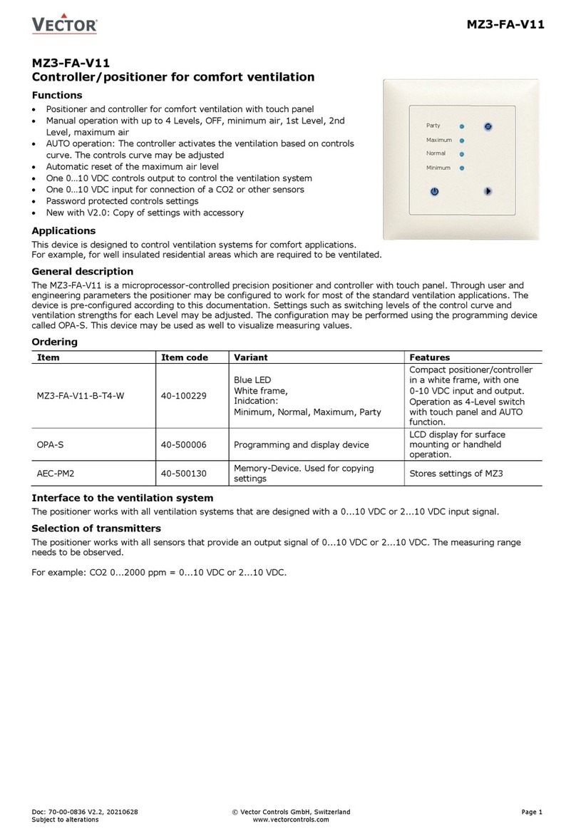
TCT-MZ2 Positioner for comfort ventilation
Functions
Positioner for comfort ventilation with time schedules
LCD Touchscreen
Fits into standard mounting frames such as Feller EDIZIOdue®
Two analog outputs for 0–10VDC with a resolution of 10mV.
One input for exhaust fan override or presence sensor
Party mode with automatic setback
Off mode with selectable ventilation interval and ventilation strength.
Selectable step or percentage set point resolution
Password protected controls settings
Background illumination
Real-time clock with schedule events
Applications
Control of ventilation systems for comfort and industrial applications
General description
The TCT-MZ is a microprocessor controlled precision positioner with real time clock and time schedules. Through user and
engineering parameters the positioner may be configured to work for most of the standard ventilation applications. The
TCT-MZ can be configured using the standard operation terminal. No special tool or software is required.
Name
Ordering
Item Name
Item code
Control Type
Key-data
TCT-MZ2-D
40-10 0212
With clock function
Compact positioner with 2 analog outputs and 1
passive input
AMM-ED-W
40-51 0086
White
Feller EDIZIOdue® Frame and mounting plate
Selection of actuators
Choose actuators with an input signal type of 0–10V DC or 2–10V DC.
Option: D = Real time clock with time schedules
Function: 2 = 2AO
Control: Z = Positioner
Outputs: M = Modulating
Series: TCT = Touchscreen operation
T
C
T
Z
-
M
2
-
D

TCT-MZ
Technical data
Doc: 70-00-0588 V1.0, 20180928 © Vector Controls GmbH, Switzerland Page 2
Subject to alteration www.vectorcontrols.com
Technical specifications
Power Supply
Operating Voltage
24 V AC/DC ± 10 %, 50/60 Hz, Class 2 48VA max
Power Consumption
Max. 1.5 VA
Electrical Connection
Terminal Connectors,
wire 0.34-2.5 mm2(AWG 24…12)
Signal inputs
Temperature Input
Range
0-50 °C (32-122 °F)
Accuracy
0.5 K
Signal outputs
Analog Outputs
Output Signal
Resolution
Maximum Load
AO1, AO2
DC 0-10 V
9.76 mV (10 bit)
10 mA
Environment
Operation
Climatic Conditions
Temperature
Humidity
To IEC 721-3-3
class 3 K5
0-50 °C (32-122 °F)
<95 % r.H. non-condensing
Transport & Storage
Climatic Conditions
Temperature
Humidity
Mechanical Conditions
To IEC 721-3-2 and IEC 721-3-1
class 3 K3 and class 1 K3
-25-70 °C (-13-158 °F)
<95 % r.H. non-condensing
class 2MT2
Standards
conform according to
EMC Standard
89/336/EEC
EMEI Standard 73/23/EEC
EN 61 000-6-1/ EN 61 000-6-3
Product standards
Automatic electrical controls for
household and similar use
Special requirement on
temperature dependent controls
EN 60 730 –1
EN 60 730 –2 –9
Degree of Protection
IP30 to EN 60529
Safety Class
III (IEC 60536)
General
Housing material:
Fire proof ABS plastic (UL94 class V-0)
Dimensions (H x W x D)
Front part: 60 x 60 x 8 mm (2.4” x 2.4” x 0.3”)
Power case: ø 58 x 27 mm (ø 2.3” x 1.1”)
Weight (including package)
115 g (4.0 oz)
Dimensions [mm] (inch)
60 (2.4)
60 (2.4)
27 (1.1)
8 (.3)
58 (2.3)

TCT-MZ
Technical data
Doc: 70-00-0588 V1.0, 20180928 © Vector Controls GmbH, Switzerland Page 3
Subject to alteration www.vectorcontrols.com
Installation and Safety advice
Caution! This device is intended to be used for comfort applications. Where a device failure endangers human life and/or
property, it is the responsibility of the owner, designer and installer to add additional safety devices to prevent or detect a
system failure caused by such a device failure. Vector Controls or its affiliates cannot be held liable for any damage
caused by such a failure. Failure to follow specifications and local regulations may endanger life, cause equipment damage
and void warranty.
Connection diagram
Description:
G0 Power supply: 0V, -24VDC, internally connected to signal common
G Power supply: 24VAC, +24VDC
M Signal common: Common 0 potential for analog inputs and analog outputs.
X1 External passive input: open contact to signal common
U1 Analog output supply air: 0…10 V DC
U2 Analog output return air: 0…10 V DC
Mounting location
On an easy accessible interior wall, approx. 1.5 m (4.5’) above the floor in an area of average temperature.
Avoid exposure to direct sunlight
Installation
Install on an easy accessible interior wall, approx. 1.5 m (4.5’) above the floor. Installation only on an on-wall or under-
wall box (frame and mounting plate is not included)
Installation:
1. Connect the wires to be connected to the terminals of the power case according to wiring diagram
2. Install the mounting plate to the flush mounting box
3. Screw the power case to the metal plate. Connectors need to point upwards!
4. Place the frame on mounting plate and hold it with one hand
5. Take the display and place it in the middle of the frame, the thick side of the display frame need to point
downwards
6. Verify that the 10 pin connector connects correctly
7. Carefully press the display on the power part until the clamps are clicking in (it may be required to move the
frame slightly).
0V (COM)
24V AC/DC
2
G
TCT-MZ2
1
G0
3
U1
Supply
OUT
4
U2
Return
OUT
7
M
Signal
COM
5
X1
X1
IN

TCT-MZ
Display and operation
Doc: 70-00-0588 V1.0, 20180928 © Vector Controls GmbH, Switzerland Page 4
Subject to alteration www.vectorcontrols.com
Display and operation
Operation Modes
STEP
Normal mode
The ventilation is operating based on selected values
OFF
Absence mode
Ventilation is operated with on and off intervals. The intensity and
duration of both on and off intervals may be defined with parameters.
The default is 5.5 hours in off mode and 0.5 hours with minimum airflow.
Party mode (FULL)
Ventilation is fully activated. The reset time is shown on the display. It
may be set.
HIGH
Full supply mode
This mode is activated by an external input for example a switch on the
kitchen or bathroom exhaust fan. The Supply air opens full and the
return air is switched off. The values of full supply mode for both supply
and return air are selectable through parameters.
Time schedule mode
Airflow is defined by time schedules
Manual override
Short term manual override of the time schedule value. After a fixed
reset time of 60 min the positioner will revert to the scheduled value.
Power Failure
All the parameters and set points are memorized and do not need to be reentered. Depending on UP03 the unit will
remain switched off, switch on automatically or return to the operation mode it was in before the power failure.
Deluxe version only: Timer operation and daytime setting will be retained for 24h. The controller has to be connected to a
power supply for at least 10 hours for the backup function to operate accordingly.
Left (POWER)
Turn unit ON or OFF. Text OFF
displayed with current time.
(Parameter setting: ESC key to
leave menu option, cancel
parameter change)
Up
Increment SET POINT
(Parameter setting: SCROLL menu
options and parameters)
Down
Decrement SET POINT
(Parameter setting: SCROLL menu
options and parameters)
Contact indication
Show when external contact close.
(Parameter setting: All bars show when
value can be changed)
Mode
Display of party, Auto or manual
mode
Large Digits
Display of step, clock or parameter
value.
Vertical Bar: Fan speed or
progress indication
Small Digits
Display of set point, clock or
parameter number.
Right (PARTY)
Toggle Party mode. In Party mode
air volume is maximum. Reset time
can be adjusted with up/down
buttons.
(Config mode: ENTER key to
change parameter and confirm
selection)
Heat/Cool
Press > 2 sec.:
Toggle Heat / Cool /
Fan only mode.
Clock
Press < 2 sec.: Enable /
disable time schedules
Press > 2 sec.: Change
time and time schedules

TCT-MZ
Display and operation
Doc: 70-00-0588 V1.0, 20180928 © Vector Controls GmbH, Switzerland Page 5
Subject to alteration www.vectorcontrols.com
Clock operation
The TCT-MZ2-D contains a quartz clock with battery back-up (not available in TCT-MZ2). Up to 8 switching events based
on time and day of the week may be programmed. A switching event is defined by the time, day of the week and
ventilation setpoint.
A blinking clock indicates that the time has not been set or that the unit has been without power for longer than 48 hours.
The time needs to be set to allow time schedules to operate.
Clock setup
Press CLOCK Key > 2 sec. SEL and current time displayed
Press RIGHT < 2 sec. to change time,
Minutes blink: UP/DOWN to change, OPTION to save minutes,
Hours blink: UP/DOWN to change, OPTION to save hour,
Press RIGHT to save time,
DAY1 blinks: UP/DOWN to change, OPTION to save day
SEL
00:00
DAY1 (Mon)
Enable/disable time schedules
Press CLOCK key < 2 sec.
Time schedule operation is enabled or disabled alternately
Creating time schedules
Step 1: Select a switching time (Up to 8, Pr01–Pr08)
Press CLOCK Key > 2 sec. SEL and current time displayed
Press UP key, Press RIGHT key to select PRO.
Press UP while PRO-ON displayed:
Large digits display Pr01, small digits display 00:00
Press RIGHT: 00:00 blinks
Press UP/DOWN to select switching time from 00:00–23:45
Press RIGHT to save switching time
Pr01
08:00
Step 2: Select day(s) of week during which the switching event shall be executed
While Pr01 is displayed and DAY1 is blinking:
Press UP: Activate switching event for DAY1 (triangle appears on 1),
Press DOWN:
Deactivate switching event for DAY1 (triangle disappears)
Press RIGHT to step to next day:
Repeat for DAY2 –DAY7
Pr01
DAY1
1 2 3 4 5 6 7
Step 3: Define setpoint
Press UP/DOWN to adjust the setpoint to the desired level
Press RIGHT button to complete. The switching event is now defined.
Pr01
08:00
Default switching times
These switching times are preprogrammed:
Monday to Sunday (Day1 to Day7:
PR01: 07:00 50%
PR02: 17:00 100%
PR03: 22:00 25%

TCT-MZ
Configuration
Doc: 70-00-0588 V1.0, 20180928 © Vector Controls GmbH, Switzerland Page 6
Subject to alteration www.vectorcontrols.com
Configuration
The TCT-MZ is preset to work for most applications. However, it can be fine-tuned for special requirements through a
simple parameter setup routine. The parameters can be changed on the unit without the need of additional equipment.
Identifying the firmware version
The parameters and functionality of controller depend on its firmware version and revision. It is therefore important to use
a matching product version and parameter set. The Firmware version and revision version can be found when pressing
simultaneously the and keys during several seconds. On the upper 7 segment display, the firmware version can be
found, on the lower 7 segment display the current revision index (or “sub-version”).
Access to parameters
The parameters can be changed as follows:
1. Press UP and DOWN button simultaneously for three seconds. The display will indicate the firmware version in the
upper large digits and the revision in the lower small digits. Pressing any key will show: CODE.
2. Select a password using UP or DOWN buttons. Select 009 in order to get access to the user parameters
Press OPTION after selecting the correct password.
3. Once logged in, the parameter is displayed immediately
4. Select the parameters with the UP/DOWN keys. Change a parameter by pressing the OPTION key. The MIN and
MAX symbols show up and indicate that the parameter may be modified now. Use UP and DOWN key to adjust
the value.
5. After you are done, press OPTION or POWER in order to return to the parameter selection level.
6. Press the POWER key again so as to leave the menu. The unit will return to normal operation if no key is pressed
for more than 5 minutes.
User Parameters (Password 009)
Parameter
Description
Range
Default
UP 00
Enable access to operation modes
ON, OFF
ON
UP 01
Enable access to set points
ON, OFF
ON
UP 02
Enable access to clock settings and time schedules
ON, OFF
ON
UP 03
State after power failure:
0 = off, 1 = on, 2 = state before power failure
0, 1, 2
2
UP 04
Reset time for party mode
0…255 min
10 min
UP 05
Reset time for manual override mode during time schedules
0…255 min
60 min
UP 06
Step or percentage control for ventilation setpoint:
OFF: Step control (# Steps defined in UP07)
ON: Percent (0…100% in 0.5% steps)
ON, OFF
OFF
UP 07
Number of steps if UP06 = OFF
0…10
5
UP 08
Time format: OFF 24H, ON 12H (AM/PM)
ON, OFF
OFF

TCT-MZ
Configuration
Doc: 70-00-0588 V1.0, 20180928 © Vector Controls GmbH, Switzerland Page 7
Subject to alteration www.vectorcontrols.com
Control Functions (Password 241)
Warning! Only experts should change these settings! See user parameters for login procedure
Parameter
Description
Range
Default
CP 00
Signal type: OFF = 0…10V, ON = 2-10V
OFF, ON
ON (2-10V)
CP 01
Min output for AO1 (TCT-MZ2 = Supply air)
0 –100 %
0%
CP 02
Max output for AO1 (TCT-MZ2 = Supply air)
0 –100 %
100%
CP 03
Min output for AO2 (TCT-MZ2 = Return air)
0 –100 %
0%
CP 04
Max output for AO2 (TCT-MZ2 = Return air)
0 –100 %
100%
CP 05
Absence mode: High time
0…25.5h
0.5h
CP 06
Absence mode: Low time
0…25.5h
5.5h
CP 07
Absence mode: Output during high time.
OFF = 0V(energy hold off) , 0…100% 0-10V or 2-10V
OFF, 0 –100 %
0%
CP 08
Absence mode: Output during low time.
OFF = 0V(energy hold off) , 0…100% 0-10V or 2-10V
OFF, 0 –100 %
OFF
CP 09
Configuration of external input (X1)
0 = Disabled
1 = Normal Absence mode changeover
2 = Full supply mode control
0…2
2
CP 10
Activation delay (seconds):
If CP 09 = 1: The time the binary input needs to be open
before absence mode is activated.
If CP 09 = 2: The time the binary input needs to be connected
to signal ground before full supply mode is activated.
0…1275s
60s
CP 11
Full supply mode: Volume for supply air
OFF = 0V (energy hold off), 0…100% 0-10V or 2-10V
OFF, 0…100%
100%
CP 12
Full supply mode: Volume for return air
OFF = 0V (energy hold off), 0…100% 0-10V or 2-10V
OFF; 0…100%
OFF
Signal limitation for VAV systems
The minimum and maximum airflow limits may be adjusted directly on the controller. A setup on the VAV
actuator is thus not required.
Absence mode
The ventilation is activated during absence mode in selectable intervals. High and Low time as well as high and
low levels of the absence mode may be defined. Per default a low time of 5.5 hours with energy hold off level is
followed by a high time of 0.5hours with minimum air flow. During energy hold off level, the ventilation is off.
Configuring the function of the external input X1
Normal –Absence mode changeover
The operation mode can be controlled through an external contact. If the contact is closed (input connected to
signal ground), normal mode is activated. If the contact is open for a time defined in CP10, absence mode is
activated. Pressing the LEFT button reactivates normal mode and resets the countdown timer defined with CP10.
A possible application is a motion detector for an office or meeting room in series with a window contact.
Full supply mode
If the contact closes, the supply air will be set to maximum (defined in CP11) and the return air set to OFF
(CP12). This function is used for kitchen exhaust or bathroom exhaust fans to prevent negative indoor pressure.
A delay may be defined with CP10.
This manual suits for next models
2
Table of contents
Other Vector Valve Positioner manuals
Popular Valve Positioner manuals by other brands

halstrup-walcher
halstrup-walcher PS*3**DP series instruction manual

Siemens
Siemens SIPART PS2 6DR50xx manual

ABB
ABB TZIDC manual

Festo
Festo CMSX-P-S-C-U-F1-D-130-A operating instructions

OMC
OMC R99P Installation, operation and maintenance instructions

Burkert
Burkert 8692 Supplement to operating instructions