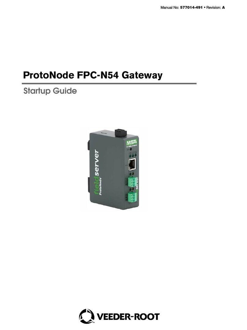
Veeder-Root QuickServer User guide

Manual No: 577014-367 •Revision: D
Startup Guide
QuickServer Industrial Protocol Gateway

ii
Notice
Veeder-Root makes no warranty of any kind with regard to this publication, including, but not limited to, the implied warranties of
merchantability and fitness for a particular purpose.
Veeder-Root shall not be liable for errors contained herein or for incidental or consequential damages in
connection with the furnishing, performance, or use of this publication.
Veeder-Root reserves the right to change system options or features, or the information contained in this publication.
This publication contains proprietary information which is protected by copyright. All rights reserved. No part of this publication may be
photocopied, reproduced, or translated to another language without the prior written consent of Veeder-Root.
Contact TLS Systems Technical Support for additional troubleshooting information at 800-323-1799.
DAMAGE CLAIMS / LOST EQUIPMENT
Thoroughly examine all components and units as soon as they are received. If any cartons are damaged or missing, write a complete
and detailed description of the damage or shortage on the face of the freight bill. The carrier's agent must verify the inspection and sign
the description. Refuse only the damaged product, not the entire shipment.
Veeder-Root must be notified of any damages and/or shortages within 30 days of receipt of the shipment, as stated in our Terms and
Conditions.
VEEDER-ROOT’S PREFERRED CARRIER
1. Contact Veeder-Root Customer Service at 800-873-3313 with the specific part numbers and quantities that were missing or
received damaged.
2. Fax signed Bill of Lading (BOL) to Veeder-Root Customer Service at 800-234-5350.
3. Veeder-Root will file the claim with the carrier and replace the damaged/missing product at no charge to the customer. Customer
Service will work with production facility to have the replacement product shipped as soon as possible.
CUSTOMER’S PREFERRED CARRIER
1. It is the customer’s responsibility to file a claim with their carrier.
2. Customer may submit a replacement purchase order. Customer is responsible for all charges and freight associated with
replacement order. Customer Service will work with production facility to have the replacement product shipped as soon as
possible.
3. If “lost” equipment is delivered at a later date and is not needed, Veeder-Root will allow a Return to Stock without a restocking fee.
4. Veeder-Root will NOT be responsible for any compensation when a customer chooses their own carrier.
RETURN SHIPPING
For the parts return procedure, please follow the appropriate instructions in the "General Returned Goods Policy” pages in the
"Policies and Literature" section of the Veeder-Root North American Environmental Products price list. Veeder-Root will not accept
any return product without a Return Goods Authorization (RGA) number clearly printed on the outside of the package.
©Veeder-Root 2019. All rights reserved.

Table of Contents
iii
Introduction
Contractor Certification Requirements ..............................................................................1
Safety Precautions ............................................................................................................1
Safety Warnings ...............................................................................................................2
Related Documents ..........................................................................................................2
Precautions Against Static Electricity ................................................................................2
QuickServer Gateway. ......................................................................................................3
Quick Start Guide ..........................................................................................................4
Setup For QuickServer
Record Identification Data ................................................................................................5
Point Count Capacity And Registers Per Device ..............................................................5
Input COM Settings on the device connected to the QuickServer ....................................6
Selecting The Desired Protocol Configuration ..................................................................6
BMS Network Settings: MAC Address Node-ID And Baud Rate ......................................7
BACnet MS/TP: Setting The MAC Address For BMS Network ................................7
Modbus RTU And Modbus TCP/IP: Setting The Node-ID........................................7
BACnet MS/TP Or Modbus RTU: Setting The Baud Rate For BMS Network ..........8
Interfacing QuickServer To Devices
QuickServer ProtoNode Showing Connection Ports .........................................................9
Device Connections To QuickServer ................................................................................9
QuickServer 6-Pin Phoenix Connector.....................................................................9
Serial Network Wiring Field Port To RS-485 Network ............................................10
Power Up QuickServer ...................................................................................................11
Using QuickServer Web Configurator To Setup The Gateway
Connect The PC To QuickServer Via The Ethernet Port ................................................12
Connecting to QuickServer Web Configurator ................................................................13
Selecting Profiles for Devices Connected to QuickServer ..............................................13
Setting BACnet Parameters ............................................................................................15
Ethernet Network - Setting IP Address For Field Network ..............................................17
How To Start The Installation Over: Clearing Profiles
BACnet EXPLORER NG ................................................................................................19
Appendix A: Troubleshooting
Lost Or Incorrect IP Address ........................................................................................ A-1
Viewing Diagnostic Information .................................................................................... A-2
Check Wiring And Settings ........................................................................................... A-2
LED Diagnostics For Communications Between QuickServer And Devices ................ A-3
Take Diagnostic Capture With The FieldServer Toolbox .............................................. A-4
Update Firmware .......................................................................................................... A-6
Unknown Alarm Category ............................................................................................. A-6
Securing QuickServer With Passwords ........................................................................ A-6
Appendix B: Vendor Information – Veeder-Root
Interface To BACnet & Modbus Tables ........................................................................ B-1
Appendix C: “A” Bank DIP Switch Settings

Table of Contents
iv
Appendix D: Reference
Specifications ................................................................................................................D-1
Compliance With UL Regulations .................................................................................D-1
Certifications - BTL Mark - BACnet® Testing Laboratory ............................................. D-2
Figures
Figure 1. QuickServer ProtoNode Connectivity Diagram (TLS450PLUS Shown).....3
Figure 2. QuickServer S Bank (Profile Selections) DIP Switches ..........................6
Figure 3. QuickServer A Bank DIP Switches .........................................................7
Figure 4. QuickServer B Bank DIP Switches .........................................................8
Figure 5. QuickServer ProtoNode Connections .....................................................9
Figure 6. QuickServer ATG RS-232 and Power Inputs .......................................10
Figure 7. QuickServer Connection To RS-485 Field Network .............................10
Figure 8. QuickServer RS-485 BMS Network EOL Switch Settings ....................10
Figure 9. Assigning Static IP Address To The PC ...............................................12
Figure 10. Web Configurator Showing No Active Profiles .....................................14
Figure 11. Web Configurator Showing Available Profiles For Selection ................14
Figure 12. Web Configurator Showing Active Profile Additions .............................15
Figure 13. Web Configurator with Protocol Set to BACnet ....................................16
Figure 14. Web Configurator Screen With Active Profiles .....................................17
Figure 15. Changing IP Address Via FS-GUI ........................................................18
Figure 16. BACnet Explorer NG On A BACnet Network ........................................19
Figure A-1. Ethernet Port Location ........................................................................ A-1
Figure A-2. Check IP Address ............................................................................... A-1
Figure A-3. Error Messages Screen ...................................................................... A-2
Figure A-4. Ethernet Port Location ........................................................................ A-3
Figure A-5. FS Toolbox Utility Screen ................................................................... A-4
Figure A-6. Selecting Full Diagnostic For Selected Device ................................... A-4
Figure A-7. Selecting Start Diagnostic For Selected Device ................................. A-5
Figure A-8. Launching Explorer To Located Device’s Diagnostic File ................... A-5
Figure A-9. FS-GUI Passwords Page .................................................................... A-7
Figure A-10. Password Recovery Page .................................................................. A-7
Tables
Table 1. QuickServer Part Number .........................................................................5
Table 2. Registers Per Device .................................................................................5
Table 3. COM Settings ............................................................................................6
Table 4. Profile Settings For QuickServer ...............................................................6
Table 5. BMS Baud Rate .........................................................................................8
Table 6. QuickServer Current Draw .....................................................................11
Table A-1. Diagnostic LED Descriptions ................................................................. A-3
Table B-1. System Veeder-Root Interface To BACnet And Modbus ...................... B-1
Table B-2. Unknown_Type Veeder-Root Interface Mappings To BACnet
And Modbus .......................................................................................... B-1
Table B-3. Tank Veeder-Root Interface To BACnet And Modbus .......................... B-2
Table B-4. Liquid Sensor Veeder-Root Interface Mappings To BACnet
And Modbus .......................................................................................... B-2
Table B-5. Input Veeder-Root Interface To BACnet And Modbus .......................... B-3
Table B-6. Type A Sensor Veeder-Root Interface To BACnet And Modbus .......... B-3
Table B-7. Type B Sensor Veeder-Root Interface To BACnet And Modbus .......... B-3
Table B-8. Vapor Sensor Veeder-Root Interface To BACnet And Modbus ............ B-3

Table of Contents
v
Table B-9. Groundwater Sensor Veeder-Root Interface To BACnet
And Modbus .......................................................................................... B-3
Table B-10. MAG Sensor Veeder-Root Interface To BACnet And Modbus .............. B-4
Table B-11. Smart Sensor Veeder-Root Interface To BACnet And Modbus ............ B-4
Table B-12. PLLD Veeder-Root Interface To BACnet And Modbus ......................... B-4
Table C-1. A Bank DIP Switch Settings For Addresses 26-50 ...............................C-1
Table C-2. A Bank DIP Switch Settings For Addresses 51 - 75 .............................C-2
Table C-3. A Bank DIP Switch Settings For Addresses 76 - 100 ...........................C-3
Table C-4. A Bank DIP Switch Settings For Addresses 101-125 ...........................C-4
Table C-5. A Bank DIP Switch Settings For Addresses 126 - 150 .........................C-5
Table C-6. A Bank DIP Switch Settings For Addresses 151 - 175 .........................C-6
Table C-7. A Bank DIP Switch Settings For Addresses 176 - 200 .........................C-7
Table C-8. A Bank DIP Switch Settings For Addresses 201 - 225 .........................C-8
Table C-9. A Bank DIP Switch Settings For Addresses 226-255 ...........................C-9
Table D-1. QuickServer ProtoNode Specifications .................................................D-1

1
Introduction
The QuickServer is an external, high performance building automation multi-protocol gateway that is preconfigured
to automatically communicate between Veeder-Root’s products (hereafter called “device”) connected to the
QuickServer and automatically configures them for BACnet MS/TP, BACnet/IP, Modbus RTU and Modbus TCP/IP.
It is not necessary to download any configuration files to support the required applications. The QuickServer is
pre-loaded with tested profiles/configurations for the supported devices.
The QuickServer ProtoNode is compatible with:
TLS-3XX Consoles hardware/software requirements:
• RS-232/RS-485 Dual Interface Module
TLS-4XX Consoles hardware/software requirements:
• RS-232/RS-485 Dual Interface Module
Contractor Certification Requirements
Veeder-Root requires the following minimum training certifications for contractors who will install and setup the
equipment discussed in this manual:
Installer Certification (Level 1): Contractors holding valid Installer Certification are approved to perform wiring
and conduit routing; equipment mounting; probe, sensor and carbon canister vapor polisher installation; wireless
equipment installation; tank and line preparation; and line leak detector installation.
Technician Certification (Level 2/3): Contractors holding valid Technician Certifications are approved to
perform installation checkout, startup, programming and operations training, system tests, troubleshooting and
servicing for all Veeder-Root Series Tank Monitoring Systems, including Line Leak Detection. In addition,
Contractors with the following sub-certification designations are approved to perform installation checkout, startup,
programming, system tests, troubleshooting, service techniques and operations training on the designated system.
•Wireless2
• Tall Tank
Warranty Registrations may only be submitted by selected Distributors.
Safety Precautions
The following safety symbols may be used throughout this manual to alert you to important safety hazards and
precautions
EXPLOSIVE
Fuels and their vapors are extremely explosive if ignited.
FLAMMABLE
Fuels and their vapors are extremely flammable.
ELECTRICITY
High voltage exists in, and is supplied to, the device. A
potential shock hazard exists.
TURN POWER OFF
Live power to a device creates a potential shock hazard.
Turn Off power to the device and associated accessories
when servicing the unit.
OFF

Introduction Safety Warnings
2
Safety Warnings
Related Documents
576013-879 TLS-3XX Console Site Prep And Installation Manual
577014-073 TLS-450PLUS Console Site Prep And Installation Manual
577013-879 TLS-450 Console Site Prep And Installation Manual
577014-110 TLS-450PLUS/TLS4 Operator’s Manual
Precautions Against Static Electricity
If necessary to install electronic components in the ATG to implement this feature, read the following static
electricity precautions:
1. Before handling any components, discharge your body's static electric charge by touching a grounded surface.
2. Do not remove parts from their anti-static bags until you are ready to install them.
3. Do not lay parts on the anti-static bags! Only the insides are anti-static.
4. When handling parts, hold them by their edges and their metal mounting brackets.
5. Avoid touching comm board components or edge connectors that plug into slots when handling.
6. Never slide parts over any surface.
7. Avoid plastic, vinyl, and Styrofoam in your work area.
Indicates a hazardous situation which, if not avoided,
could result in death or serious injury.
READ ALL RELATED MANUALS
Knowledge of all related procedures before you begin
work is important. Read and understand all manuals thor-
oughly. If you do not understand a procedure, ask some-
one who does.
WARNING
This console contains high voltages which can be lethal. It is also connected to low
power devices that must be kept intrinsically safe.
FAILURE TO COMPLY WITH THE FOLLOWING WARNINGS AND SAFETY
PRECAUTIONS COULD CAUSE DAMAGE TO PROPERTY, ENVIRONMENT,
RESULTING IN SERIOUS INJURY OR DEATH.
1. Turn off and tag power at the circuit breaker. Do not connect the console AC
power supply wires at the breaker until all devices are connected.
2. Attach conduit from the power panel to the console's Power Area knockouts
only.
3. Comply with all applicable codes including: the National Electrical Code;
federal, state, and local codes; and other applicable safety codes.
Connecting power wires to a live circuit can cause electrical shock that may result in
serious injury or death.
Routing conduit for power wires into the intrinsically safe compartment can result in
fire or explosion resulting in serious injury or death.
WARNING
OFF

3
Introduction QuickServer Gateway.
QuickServer Gateway.
Figure 1. QuickServer ProtoNode Connectivity Diagram (TLS450PLUS Shown)

4
Quick Start Guide
1. Record the information about the unit. ( page 5)
2. Set the device’s COM settings for each of the devices that are to connect to the QuickServer. ( page 6)
3. Select the protocol configuration on the S Bank DIP switches. ( page 6)
4. BACnet MS/TP: Set the MAC Address on the A Bank DIP switches. ( page 7)
5. Modbus RTU or Modbus TCP/IP: Set the Node-ID. ( page 7)
6. BACnet MS/TP or Modbus RTU: Set the baud rate of the field protocol on the B Bank DIP switches. (
page 8)
7. Connect the QuickServer 6-pin RS-232 connector to the Veeder-Root ATG. ( page 9)
8. Connect the QuickServer ProtoNode 3 pin RS-485 port to the field protocol cabling. ( page 10)
9. Connect power to the QuickServer 6-pin connector. ( page 11)
10.Use a web browser to access the QuickServer Web Configurator page to select the profiles of the devices
attached to the QuickServer and input the Node-ID from each device. Once the devices are selected, the
QuickServer automatically builds and loads the appropriate configuration. ( page 12)
11.BACnet MS/TP or BACnet/IP: Set the BACnet Device Instance. ( page 15)
12.Ethernet Network: Use a web browser to access the QuickServer Web Configurator page to change the IP
Address. No changes to the configuration are necessary. ( page 17)
1
2
3
4
5
6
7
8
9
10
11
12

5
Setup For QuickServer
Record Identification Data
The QuickServer has a unique part number located on the side or the back of the unit. This number should be
recorded, as it may be required for technical support. The numbers are as follows:
QuickServer ProtoNode units have the following 3 ports: RS-232 , Ethernet and RS-485.
Point Count Capacity And Registers Per Device
The total number of points presented by the device attached to the QuickServer ProtoNode-1504 cannot exceed
5000.
The total number of points per QuickServer profile is shown in Table 2:
Table 1. QuickServer Part Number
Model Part Number
QuickServer ProtoNode 330020-840 /
330020-841
Table 2. Registers Per Device
Profile Points Per Device
System 29
Unknown Type 3
Tank 56
Liquid Sensor 9
Input 6
Type A Sensor 5
Type B Sensor 6
Vapor Sensor 9
Groundwater Sensor 9
MAG Sensor 14
Smart Sensor 17
PLLD 19
1

Setup For QuickServer Input COM Settings on the device connected to the QuickServer
6
Input COM Settings on the device connected to the QuickServer
•The connected serial device MUST have the same baud rate, data bits, stop bits, and parity settings as the
QuickServer.
•To set the QuickServer’s COM settings, See “Connecting to QuickServer Web Configurator” on page 13.
•Table 3 specifies the device serial port settings required to communicate with the QuickServer.
Selecting The Desired Protocol Configuration
QuickServer ProtoNode units use the ‘S’ bank of DIP switches (S0 - S3) to select the protocol configuration (see
Figure 2).
Figure 2. QuickServer S Bank (Profile Selections) DIP Switches
See Table 4 for the S Bank DIP switch settings.
Table 3. COM Settings
Port Setting TLS-3XX/TLS4XX
Protocol V-R Interface
Baud Rate 9600
Parity Odd
Data Bits 7
Stop Bits 1
Table 4. Profile Settings For QuickServer
QuickServer ProtoNode S Bank DIP Switches
Profile S0 S1 S2 S3
BACnet/IP Off Off Off Off
BACnet MS/TP On Off Off Off
2
3
S0
S1
S2
S3
Off On
S0 - S3 DIP Switches Bank DIP Switch Location
When setting DIP switches,
ensure that power to the
board is OFF.
NOTICE

7
Setup For QuickServer BMS Network Settings: MAC Address Node-ID And Baud Rate
BMS Network Settings: MAC Address Node-ID And Baud Rate
BACNET MS/TP: SETTING THE MAC ADDRESS FOR BMS NETWORK
•Only 1 MAC Address is set for QuickServer regardless of how many devices are connected to QuickServer.
•Set the BACnet MS/TP MAC Address of the QuickServer to a value between 1 to 127 (Master MAC Address);
this is so that the BMS front end can find QuickServer via BACnet Auto-Discovery.
Never set a BACnet MS/TP MAC Address of the QuickServer to a value from 128 to 255.
Addresses from 128 to 255 are Slave Addresses and can not be discovered by BMS front
ends that support Auto-Discovery of BACnet MS/TP devices.
•Set “A” bank DIP switches A0 – A7 to assign a MAC Address to the QuickServer for BACnet MS/TP (see
Figure 3).
Figure 3. QuickServer A Bank DIP Switches
•Refer to Appendix C for the complete range of MAC Addresses and DIP switch settings.
MODBUS RTU AND MODBUS TCP/IP: SETTING THE NODE-ID
•The Modbus RTU and Modbus TCP/IP Node-IDs are assigned by setting the A-bank dip switches. (see
Figure 3).
•Node-ID’s range from 1-255. Refer to Appendix C for the full range of addresses for setting Node-ID.
Modbus TCP/IP and Mod-
bus RTU
Off On Off Off
Table 4. Profile Settings For QuickServer (Continued)
QuickServer ProtoNode S Bank DIP Switches
Profile S0 S1 S2 S3
4
NOTICE
A0 - A7 DIP Switches Bank DIP Switch Location
A0
A1
A2
A3
A4
A5
A6
A7
Off On
When setting DIP switches,
ensure that power to the
board is OFF.
NOTICE
5

Setup For QuickServer BMS Network Settings: MAC Address Node-ID And Baud Rate
8
BACNET MS/TP OR MODBUS RTU: SETTING THE BAUD RATE FOR BMS NETWORK
DIP switches B0 – B3 can be used to set the field baud rate of the QuickServer to match the baud rate required
by the BMS for BACnet MS/TP (see Figure 4).
Figure 4. QuickServer B Bank DIP Switches
BMS baud rate dip switch selections are shown in Table 5.
.
*Factory default setting.
Table 5. BMS Baud Rate
Baud Rate B0 B1 B2 B3
9600 On On On Off
19200 Off Off Off On
38400* On On Off On
57600 Off Off On On
76800 On Off On On
6
B0 - B3 DIP Switches Bank DIP Switch Location
B0
B1
B2
B3
Off On
When setting DIP switches,
ensure that power to the
board is OFF.
NOTICE

9
Interfacing QuickServer To Devices
QuickServer ProtoNode Showing Connection Ports
Figure 5. QuickServer ProtoNode Connections
Device Connections To QuickServer
QUICKSERVER 6-PIN PHOENIX CONNECTOR
•Pins 1 - 3 are for Veeder-Root ATG input (see Figure 6).
•Pins 4 - 6 are for QuickServer power. QuickServer accepts either 9-30V DC or 12-24V AC on pins 4 and 5.
Do not power up QuickServer at this time.
Phoenix
Connector
7
NOTICE

Interfacing QuickServer To Devices Device Connections To QuickServer
10
Figure 6. QuickServer ATG RS-232 and Power Inputs
SERIAL NETWORK WIRING FIELD PORT TO RS-485 NETWORK
•Connect the RS-485 network wires to the 3-pin RS-485 connector on QuickServer ProtoNode as shown in
Figure 7.
Figure 7. QuickServer Connection To RS-485 Field Network
•See “Ethernet Network - Setting IP Address For Field Network” on page 17. for information on connecting to
BACnet/IP network.
•If the QuickServer is the last device on the trunk, then the End-Of-Line Termination Switch needs to be set to
the On position (the EOL Termination default setting is Off). If necessary, set the switch to the On position
(see Figure 8).
Figure 8. QuickServer RS-485 BMS Network EOL Switch Settings
Pin 3 Rx/-
Pin 2 Tx/+
Pin 5 GND
Pin 3 Rx/-
Pin 2 Tx/+
Pin 7 GND Power In (+)
Power In (-)
Frame Ground (must be connected)
Pin 1 Pin 6
(If 25 Pin) (If 9 Pin)
Power
Input
Use standard grounding
principles for RS-232 GND.
NOTICE
Console RS-232 Connector
8
RS-485 (+)
RS-485 (-)
RS-485 GND
BMS
Input
Pin 1
Pin 3
Off (Default)
On
EOL Switch

11
Interfacing QuickServer To Devices Power Up QuickServer
Power Up QuickServer
Verify QuickServer nominal power requirements in Table 6.
These values are ‘nominal’ and a safety margin should be added to the power supply of the
host system. A safety margin of 25% is recommended.
After verifying power source and with frame ground connected as shown in Figure 6. apply power to QuickServer.
Table 6. QuickServer Current Draw
QuickServer ProtoNode
Current Draw
12V DC/AC 24V DC/AC 30V DC
Typical 170 mA 100 mA‘ 80 mA
Maximum 240 mA 140 mA 100 mA
9
NOTICE

12
Using QuickServer Web Configurator To Setup The Gateway
Connect The PC To QuickServer Via The Ethernet Port
•Connect a CAT5 Ethernet cable (Straight through or Cross-Over) between the local PC and QuickServer.
•The Default IP Address of QuickServer is 192.168.1.24, subnet mask is 255.255.255.0. If the PC and
QuickServer are on different IP Networks, assign a static IP Address to the PC on the 192.168.1.xxx network:
For Windows 10, Right click on . Then click on Network Connections>Change Adapter Options. Double
click on Local Area Connections. When the Local Area Connections Status box appears click Properties. Click
on Internet Protocol Version 4 (TCP/IPv4) then click Properties. When the Internet Protocol Version 4 (TCP/
IPv4) Properties dialog box appears, click, ‘Use the following IP address’ radio button and enter the ‘IP address’
and ‘Subnet mask’ entries shown in Figure 9, the click the OK button , then the Close buttons to exit.
Figure 9. Assigning Static IP Address To The PC
10

13
Using QuickServer Web Configurator To Setup The Gateway Connecting to QuickServer Web Configurator
After disconnecting from the QuickServer return to the PC’s Internet Protocol Version 4 (TCP/IPv4) Properties
dialog box and click the Obtain an IP Address Automatically’ radio button to return the PC to its original Local Area
Connection settings.
Connecting to QuickServer Web Configurator
After setting a local PC on the same subnet as the QuickServer (refer to above paragraph), open a web browser
on the PC and enter the IP Address of the QuickServer (the default address is 192.168.1.24).
If the IP Address of the QuickServer was changed, the assigned IP Address can be
discovered using the FS Toolbox utility. See ‘Lost Or Incorrect IP Address’ (Appendix A, page
A-1) for instructions.
Selecting Profiles for Devices Connected to QuickServer
•In the Web Configurator, the Active Profiles are shown below the Configuration Parameters.
•Fill in the parameter values as needed.
-Enter the Veeder-Root PLC Type and COM settings.
See “Input COM Settings on the device connected to the QuickServer” on page 6 for
correct COM settings per PLC Type.
-Once a parameter value is changed as desired click Submit to save it.
•The Active profiles section lists the currently active device profiles, including previous Web Configurator
additions. This list is empty for new installations, or after clearing all configurations (see Figure 10).
•To add an active profile to support a device, click the Add button under the Active Profiles heading. This will
present a drop-down box underneath the Current profile column that lists all the available profiles (see
Figure 11).
•Once the profile for the device has been selected from the drop-down list, enter the value of the Node-ID.
The first entered Node-ID must be set to “1” and be followed by sequential values.
•Then enter the Address Parameter. The Address is used to specify the tank, sensor or input number. This
information can be found in the Veeder-Root ATG Report.
-Tanks are addressed from 1-12.
-Sensors are addressed from 1-64.
-Inputs are addressed from 1-64.
•Then press the “Submit” button to add the Profile to the list of devices to be configured.
•Repeat this process until all the devices have been added.
NOTICE
NOTICE
NOTICE

Using QuickServer Web Configurator To Setup The Gateway Selecting Profiles for Devices Connected to QuickServer
14
Figure 10. Web Configurator Showing No Active Profiles
Figure 11. Web Configurator Showing Available Profiles For Selection

15
Using QuickServer Web Configurator To Setup The Gateway Setting BACnet Parameters
•Completed additions are listed under “Active Profiles” as shown the Figure 12 example.
Figure 12. Web Configurator Showing Active Profile Additions
Figure 12 shows a console with 3 tanks and 4 liquid sensors. The node IDs are sequential, starting with 1; the
addresses match the console numbering of the tanks (i.e., there is no tank 3 set up in the console). The Node
ID is used for the BACnet Object or Modbus Register (see Appendix B) and its address must match the device
number programmed in the console.
System and Unknown Type points are automatically configured therefore no profile is
required. Refer to Table B-1 and Table B-2 in Appendix B for a list of available points.
Setting BACnet Parameters
•Open the Web Configurator with the protocol set to BACnet in “Selecting The Desired Protocol Configuration”
on page 6.
•Fill in the parameter values as needed (see Figure 13).
-Enter the Veeder-Root PLC Type, COM settings and BACnet settings (Bac_device_id)
See See “Input COM Settings on the device connected to the QuickServer” on page 6.
for correct COM settings per PLC Type.
The Bac_device_id field will display the current value (default = 50,000). The BACnet
Device Instance can range from 1 to 4,194,303.
-Once a parameter value is changed as desired click Submit to save it.
NOTICE
11
NOTICE
Table of contents
Other Veeder-Root Gateway manuals