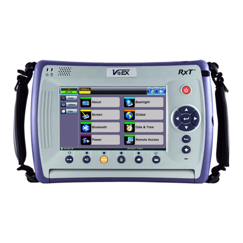
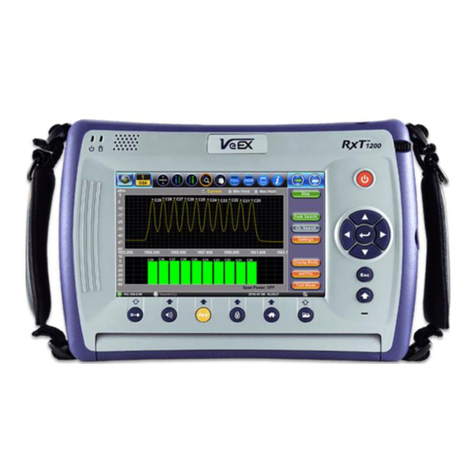
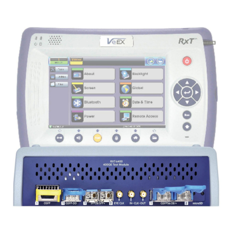
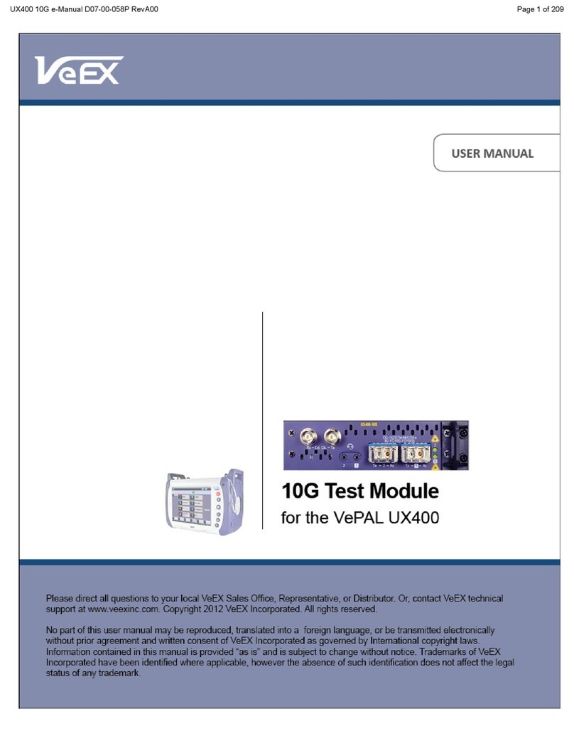
VeEX RXT-3000 User manual

RXT-3000 e_Manual D07-00-088P RevA00
Page 1 of 415

Table of Contents
1.0 About This User Manual
2.0 Introduction
3.0 Safety Information
4.0 Basic Operations
5.0 Utilities
6.0 Setup
6.1 Signal Overview
6.2 Setup: PDH
6.2.1 Transmitter Setup
6.2.2 Receiver Setup
6.3 Setup: SDH
6.3.1 Transmitter Setup
6.3.2 Receiver Setup
6.4 Setup: SONET
6.4.1 Transmitter Setup
6.4.2 Receiver Setup
6.5 Setup: OTN/SDH
6.5.1 Transmitter Setup
6.5.2 Receiver Setup
6.6 Setup: OTN/SONET
6.6.1 Transmitter Setup
6.6.2 Receiver Setup
6.7 Measurement Configuration
6.7.1 Timer Setup
6.7.2 Performance Analysis
6.7.3 General
6.7.4 Auto-Config
RXT-3000 e_Manual D07-00-088P RevA00
Page 2 of 415

7.0 Results
7.1 Results: PDH
7.1.1 Summary
7.1.2 Errors and Alarms
7.1.3 Event Log
7.1.4 Signal
7.1.5 Histogram
7.1.6 Graph
7.1.7 Performance Analysis
7.2 Results: SDH
7.2.1 Summary
7.2.2 Errors and Alarms
7.2.3 Event Log
7.2.4 Signal
7.2.5 Histogram
7.2.6 Graph
7.2.7 Performance Analysis
7.3 Results: SONET
7.3.1 Summary
7.3.2 Errors and Alarms
7.3.3 Event Log
7.3.4 Signal
7.3.5 Histogram
7.3.6 Graph
7.3.7 Performance Analysis
7.4 Results: OTN
7.4.1 Summary
7.4.2 Errors and Alarms
8.0 Alarms/Errors
RXT-3000 e_Manual D07-00-088P RevA00
Page 3 of 415

8.1 Alarm Generation
8.1.1 PDH Alarms
8.1.2 SDH Alarms
8.1.3 OTN Alarms
8.2 Error Insertion
8.2.1 PDH & T-Carrier Errors
8.2.2 SDH Errors
8.2.3 OTN Errors
9.0 OTN Tools
9.1 Shortcuts
9.2 Overhead Analyzer & Generator
9.2.1 OTN Frame Analysis
9.2.2 Optical Transport Unit (OTU) Analysis
9.2.3 Optical Data Unit (ODU) Analysis
9.2.4 Optical Payload Unit (OPU) Analysis
9.3 Payload Label
9.4 Trace Identifier
9.5 TCM Tasks
10.0 SDH/SONET Tools
10.1 SDH/SONET Tools
10.1.1 Shortcuts
10.1.2 Overhead Analyzer
10.1.3 Overhead Generator
10.1.4 Pointer Tasks
10.1.4.1 Pointer Analysis
10.1.4.2 Pointer Generation
10.1.4.3 Pointer Sequences
10.1.5 Trace Identifier
10.1.5.1 Transmitted Traces (TX)
RXT-3000 e_Manual D07-00-088P RevA00
Page 4 of 415

10.1.5.2 Received Traces (RX)
10.1.6 Payload Labels
10.1.7 APS Tasks
10.1.7.1 APS Timing
10.1.7.2 APS Sequence
10.1.8 Tandem Connection Monitoring (TCM)
10.1.9 Tributary Scan
10.1.10 Round Trip Delay
10.1.11 Jitter and Wander
10.2 SONET Tools
10.2.1 Shortcuts
10.2.2 Overhead Analyzer
10.2.3 Overhead Generator
10.2.4 Pointer Tasks
10.2.4.1 Pointer Analysis
10.2.4.2 Point Generator
10.2.4.3 Pointer Sequences
10.2.5 Trace Identifier
10.2.5.1 Transmitted Traces (TX)
10.2.5.2 Received Traces (RX)
10.2.6 Payload Labels
10.2.7 APS Tasks
10.2.7.1 APS Timing
10.2.7.2 APS Sequence
10.2.8 Tandem Connection Monitoring (TCM)
10.2.9 Tributary Scan
10.2.10 Round Trip Delay
10.2.11 Jitter and Wander
11.0 PDH Tools
11.1 E1 Pulse Mask
RXT-3000 e_Manual D07-00-088P RevA00
Page 5 of 415

11.2 E3 Pulse Mask
11.3 E1 APS Testing
11.4 E1 Frame Words
11.5 Round Trip Delay
11.6 E1 RX Data
11.7 E1 ISDN PRI
11.7.1 ISDN PRI Call
11.7.1.1 Setup (PRI Call Setup)
11.7.1.2 Signal
11.7.1.3 Call - Voice and 3.1K Audio Setup
11.7.1.4 Call - Data Setup
11.7.1.5 Data Call BERT Results (Result tab)
11.7.1.6 Supplementary Service Scan
11.7.1.7 Multi Call
11.7.1.8 DTMF
11.7.2 ISDN PRI Monitor
11.8 E1 VF
11.9 Jitter & Wander
12.0 DS1/3 Tools
12.1 DS1 Pulse Mask
12.2 DS1 Loop
12.3 Round Trip Delay
12.4 DS1 RX Data
12.5 DS3 Pulse Mask
12.6 DS3 FEAC
12.7 DS1 ISDN PRI
12.8 DS1 VF Tasks
12.9 Jitter & Wander
12.10 CSU/NIU Emulation
RXT-3000 e_Manual D07-00-088P RevA00
Page 6 of 415

13.0 Jitter and Wander Application
13.1 Jitter Measurement & Generation (Jitter icon)
13.2 Max Jitter Tolerance
13.3 Jitter Transfer Function
13.4 Wander Measurement
13.4.1 Setup
13.4.2 Wander Result
13.4.3 Wander Analysis PC Software
14.0 OTU-Xe
14.1 OTU-Xe Overview
14.2 OTN Setup
14.2.1 Signal Setup
14.2.1.1 Hierarchy
14.2.1.2 Interface
14.2.1.3 Pattern
14.2.2 Measurements
14.2.3 General
14.3 OTN Results
14.3.1 Summary
14.3.2 Errors/Alarms
14.3.3 Event Log
14.3.4 Signal
14.4 OTU-Xe Ethernet Applications
14.4.1 OTU-Xe with 10GE BERT
14.4.2 OTN/10GE RFC 2544 Conformance Testing
14.4.3 OTN/10GE Throughput Testing (Multiple Streams)
15.0 Ethernet
15.1 Ethernet Setup
15.1.1 Test Port Selection
RXT-3000 e_Manual D07-00-088P RevA00
Page 7 of 415

15.1.2 Port Setup
15.1.3 Measurement Settings
15.1.3.1 Clock Synchronization Process
15.1.4 MX Discover and Control
15.1.5 ViPAG Router Test
15.2 BERT
15.2.1 BERT Setup
15.2.1.1 Header Settings
15.2.1.2 Traffic Settings
15.2.1.3 Error Injection
15.2.1.4 Starting/Stopping a BERT
15.2.2 Results
15.2.2.1 Summary
15.2.2.2 Errors
15.2.2.3 Events
15.2.2.4 Traffic
15.2.2.5 Rates
15.2.2.6 Delay
15.2.2.7 Alarms
15.2.2.8 Signal
15.3 RFC 2544 Conformance Testing
15.3.1 Setup - Standard Mode
15.3.1.1 Header Settings
15.3.1.2 Frame Settings
15.3.1.3 Threshold Settings
15.3.1.4 Peer-to-Peer and Asymmetric Testing
15.3.1.5 Throughput, Latency, Frame Loss, and Burst Settings
15.3.1.6 Starting/Stopping a RFC 2544 Measurement
15.3.2 Results - Standard Mode
15.3.3 Saving RFC 2544 Results
15.3.4 Advanced SLA Mode
15.3.5 Background Results - Advanced SLA Mode
RXT-3000 e_Manual D07-00-088P RevA00
Page 8 of 415

15.4 V-SAM
15.4.1 V-SAM Setup
15.4.1.1 Header Settings
15.4.1.2 Service Attributes
15.4.2 Results
15.5 Throughput Testing (Multiple Streams)
15.5.1 Setup
15.5.1.1 General Throughput Settings (Global Configuration)
15.5.1.2 MX Discover and Control Settings
15.5.1.3 Per Stream Configurations
15.5.1.4 Traffic Settings (Per Stream Configuration)
15.5.1.5 Error Injection Settings per Stream
15.5.1.6 Summary
15.5.1.7 Starting/Stopping a Throughput (Multiple Streams) Test
15.5.2 Throughput Results
15.5.2.1 Viewing Throughput (Multiple Streams) Test Results
15.5.2.2 Global/Aggregate Results
15.5.2.3 Per Stream Results
15.5.2.4 Saving Throughput (Multiple Streams) Results
15.6 Ethernet OAM Testing
15.6.1 OAM Setup
15.6.1.1 Link Level 802.3ah OAM Setup
15.6.1.2 Service Level OAM: 802.1ag/Y.1731 Setup
15.6.2 OAM Results
15.6.2.1 Link OAM Results
15.6.2.2 OAM Service Results
15.7 Monitor (Pass Through) Mode
15.7.1 Setup
15.7.2 Results
15.8 Loopback Mode
15.9 Advanced Tools
RXT-3000 e_Manual D07-00-088P RevA00
Page 9 of 415

15.10 SyncE
15.10.1 SyncE Setup
15.10.2 SyncE Wander Measurements
15.11 1588v2
15.11.1 IP and Port Setup
15.11.2 Mode Setup
15.11.2.1 Master Emulation Mode Setup
15.11.2.2 Master Clock Settings
15.11.2.3 Slave Emulation Mode Setup
15.11.2.4 Slave Clock Settings
15.11.3 Test Results
15.11.4 Protocol Monitor
16.0 Fiber Channel
16.1 Setup
16.1.1 Test Applications
16.1.2 Port Configuration
16.2 BERT/Throughput
16.2.1 Overview
16.2.2 Setup
16.2.3 Traffic Generation and Error Injection
16.2.4 Starting Measurements
16.2.5 Results
16.3 RFC 2544
16.4 Loopback
17.0 CPRI Optical Testing
17.1 Interface Specifications
17.2 CPRI Testing
17.2.1 CPRI Unframed Setup
17.2.1.1 Test Pattern
17.2.1.2 Traffic Pattern
RXT-3000 e_Manual D07-00-088P RevA00
Page 10 of 415

17.2.1.3 Error Injection
17.2.2 Results
17.2.2.1 Summary
17.2.2.2 Signal
17.2.2.3 Errors
17.2.2.4 Alarms
17.2.2.5 Events
17.2.2.6 Saving and Retrieving Results
17.3 CPRI Layer 1 Framed Testing
17.3.1 Setup
17.3.2 Results
17.4 CPRI Layer 2 Framed Testing
17.4.1 Setup
17.4.2 Results
17.4.3 CPRI Round Trip Delay
17.4.4 SDT
17.4.5 Control Words
18.0 Profiles
19.0 Common Functions
20.0 Warranty and Software
21.0 Product Specifications
22.0 Certifications and Declarations
23.0 About VeEX
Go back to top
RXT-3000 e_Manual D07-00-088P RevA00
Page 11 of 415

1.0 About This User Manual
This user manual is suitable for novice, intermediate, and experienced users and is intended to help you successfully use the
features and capabilities of the different modules for test platforms. It is assumed that you have basic computer experience and
skills, and are familiar with IP and telecommunication concepts, terminology, and safety.
Every effort was made to ensure that the information contained in this manual is accurate. However, information is subject to
change without notice. We accept no responsibility for any errors or omissions. In case of discrepancy, the web version takes
precedence over any printed literature.
NOTE: The screenshots in this manual are from TX300 test sets and have been included for reference only.
(c) Copyright 2006-2015 VeEX Inc. All rights reserved. VeEX, VePAL are registered trademarks of VeEX Inc. and/or its affiliates
in the USA and certain other countries. All trademarks or registered trademarks are the property of their respective companies.
No part of this document may be reproduced or transmitted electronically or otherwise without written permission from VeEX Inc.
This device uses software either developed by VeEX Inc. or licensed by VeEX Inc. from third parties. The software is confidential
and proprietary of VeEX Inc. The software is protected by copyright and contains trade secrets of VeEX Inc. or VeEX's licensors.
The purchaser of this device agrees that it has received a license solely to use the software as embedded in the device, and the
purchaser is prohibited from copying, reverse engineering, decompiling, or disassembling the software.
For more technical resources, visit the VeEX Inc. web site at www.veexinc.com. For assistance or questions related to the use of
this product, call or e-mail our customer care department for customer support. Before contacting our customer care department,
have the product serial number and software version ready. Please go to the Basic Operations section for details on locating the
unit serial number in the menus or locate the serial number on the back of the chassis. Please provide this number when
contacting VeEX customer service.
Customer Care:
Phone: + 1 510 651 0500
E-mail: [email protected]
Website: www.veexinc.com
Go back to top Go back to TOC
RXT-3000 e_Manual D07-00-088P RevA00
Page 12 of 415

2.0 Introduction to RXT-3000
RXT-3000 Combo
RXT-3000 Combo's all-inclusive hardware includes all physical interfaces and allows activating technologies, rates, protocols and
test features via licenses, as required.
XFP and SFP Optical Test Ports
RJ45 10/100/1000Base-T Test Port
BNC and RJ48/Bantam Electrical Test Ports (PDH/DSn and clock output)
External Clock Reference Input (SMA, 75 Ohms)
Uses Platforms’ GPS or Atomic Clock References (optional HW)
Headset audio jack (2.5mm TRS)
VeExpress Client
All Test Features and Technologies are Field-upgradeable
Keeps licenses up-to-date
Allows License Sharing among RXT-Combo modules
R-Server Client option
Upload Test Results and Test Profiles to a centralized server
Transport Networks:
OTN
OTU1, OTU2, OTU1e, OTU2e Line Rates
ODU0, ODUflex mappings
Bulk (PRBS), SDH/SONET+PDH/DSn and Ethernet Payloads
SDH/SONET
STM-0 to STM-64
STS-1 to OC-192
Bulk (PRBS) and PDH/DSn Payloads
PDH/DSn
DS1, DS3, E1, E3, E4
Unframed, Framed and Structured (Channelized) Payloads
ISDN PRI, VF Channel Access
Packet Switched Networks
Ethernet
From 10 Mbps to 10 Gbps LAN/WAN, copper and fiber
IPv4/IPv6, VLAN, MPLS, MPLS-TP, PBB, VoIP, IPTV,…
RFC2544 SLA, Y.1564 V-SAM, OAM/MPLS-TP OAM (802.3ah, 802.1ag, Y.1731, G.8113.1)
Layer 4 Throughput applications: V-PERF (TCP), VeTest (HTTP), FTP
SyncE
Master and Slave Emulation
Clock Recovery and Translation
Wander Measurements
RXT-3000 e_Manual D07-00-088P RevA00
Page 13 of 415

1588v2 PTP (Precision Timing Protocol)
Master and Slave Emulation with Clock Recovery and Translation
PTP Message Capture, Decode and Export (pcap)
Wander and Phase Measurements
Fibre Channel (Storage Area Networks)
1, 2, 4, 8 and 10 Gbps
Wireless Networks
CPRI
Common Public Radio Interface
From 614.4 Mbps up to 9.8304 Gbps
OBSAI
Open Base Station Architecture Initiative
From 768 Mbps up to 6.144 Gbps
Clock Accuracy and Stability Assessment
Wander Measurement and Analysis
Absolute Phase (Timing) Error Measurement and Analysis (1PPS clocks)
External or built-in precision reference clocks (GPS and Atomic options)
Backhaul Testing
Ethernet, VLAN, Q-in-Q, MPLS-TP, OAM,…
1588v2 PTP, SyncE
Clock Stability (Wander) and Timing Accuracy (Phase)
Network Synchronization
Synchronous Ethernet (SyncE)
Master/Slave Emulation with clock recovery/translation and SSM/ESMC Monitor
1588v2 / PTP (Precision Timing Protocol)
Master/Slave Emulation with clock recovery/translation, PDV Analysis and SSM/ESMC Monitor
Wander Measurement & Analysis
Recovered Clock Accuracy and Stability assessment
Long term TIE log and MTIE/TDEV post processing with Pass/Fail analysis based on standard or user-defined
masks
Built-in Precision Reference Clock Options (RXT Platform)
GPS provides accurate phase aligned to the standard UTC second
Atomic Clock provides high stability, required for field wander and phase measurements
Portability - No physical reference signal or power are required
One-way Delay Measurements
1588v2 PTP requires the links to be symmetrical (similar delay both directions)
Go back to top Go back to TOC
RXT-3000 e_Manual D07-00-088P RevA00
Page 14 of 415

3.0 Safety Information
Safety precautions should be observed during all phases of operation of this instrument. The instrument has been designed to
ensure safe operation however please observe all safety markings and instructions. Do not operate the instrument in the
presence of flammable gases or fumes or any other combustible environment. VeEX Inc. assumes no liability for the customer's
failure to comply with safety precautions and requirements.
Optical Connectors
The test sets display a laser warning icon when the laser source is active to alert the user about a potentially dangerous
situation. It is recommended to:
1. Deactivate the laser before connecting or disconnecting optical cables or patchcords.
2. Never look directly into an optical patchcord or an XFP's or SFP’s connector interface while the laser is enabled. Even
though XFP and SFP optical transceivers are typically fitted with Class 1 lasers, which are considered eye safe, optical
radiation for an extended period can cause irreparable damage to the eyes.
3. Never use a fiber microscope to check the optical connectors when the laser source is active.
Electrical Connectors
Telephone lines may carry dangerous voltages. Always connect the electrical test ports to known test interfaces which carry low
level signals.
Go back to TOC
RXT-3000 e_Manual D07-00-088P RevA00
Page 15 of 415

6.0 OTN, SDH/SONET, PDH/DSn Test Mode
Accessing Setup: Please see the RXT-1200 Platform manual Getting Started section to launch Test Applications.
SONET Home Menu
The Setup page has four tabs for setting the OTN, SDH/SONET, and PDH parameters: Signal, Measurements, General, and
Auto-Config tabs.
Go back to top Go back to TOC
6.1 Signal Overview
Tap on the Signal tab to set up the Transmitter and Receiver interfaces and associated test parameters prior to running a test.
Signal tab
TX and RX Configurations
The Transmitter (TX) and Receiver (RX) configurations are grouped into a simple yet intuitive block diagram. The TX and RX
signal parameters can be modified by tapping the applicable block which brings up a new dialog window displaying additional
input and specific selection settings. The Transmitter transmits as soon as a valid configuration is entered. The Receiver will
check for a valid signal on its input so the measurement function is synchronized. When a test is not running, the LEDs will still
indicate errors and alarms, but any other results displayed will be the results of a previous test.
RXT-3000 e_Manual D07-00-088P RevA00
Page 18 of 415

Coupling TX and RX
When the TX and RX signal structures are required to be identical or symmetrical, coupling the Transmitter and Receiver is
possible. Tap on the blue "TX" or "RX" header to bring up the Copy menu. Copy menu options are Coupled, Tx=Rx, and Rx=Tx.
Accessing the Copy Menu
Copy Menu Options
Coupled: TX and RX configurations are grouped as one block; TX and RX will have identical configuration. To uncouple
TX and RX settings, tap on the blue "Coupled" heading and select Independent from the Copy Menu.
Tx=Rx: Tx blocks will copy the settings made in the Rx blocks
Rx=Tx: Rx blocks will copy the settings made in the Tx blocks
Changes to the Setup are applied immediately unless an invalid parameter has been selected.
When the TX and RX signal structures need to be independent or asymmetrical, uncoupling the transmitter and receiver is
possible. For example, the TX could be sending a PRBS of 2^23-1 in a VC12 carried within an optical STM-64, while the RX
could be expecting to receive a PRBS of 2^23-1 in a 2Mbps E1 signal.
Hierarchy: Allows the user to configure OTN/SDH, OTN/SONET, PDH signal and network types, including the bit rate and higher
order mapping, if applicable.
Interface: Allows the user to select optical or electrical test ports. Optical test ports apply to OTN/SDH signal types only, while
electrical ports can apply to STTM-1E or PDH signals. Clock source and offset options are also configured in this screen.
Structure: Applies to SDH/SONET signals only and allows the user to configure lower order mapping and the channel number.
Payload: Applies to both SDH/SONET and PDH signals and allows the user to configure low rate signal (if applicable) and
associated framing.
Pattern: Applies to both SDH/SONET and PDH signals and allows the user to configure the test pattern to be used. Use the
pattern drop-down box to select the test pattern which will be inserted into the transmitted signal. Pseudo Random Bit
Sequences (PRBS) defined by ITU-T 0.150 and 0.151 standards, fixed words and 24-bit or 32 bit user defined patterns are
available. Note, if the 32 bit user pattern entered is incorrect, the default pattern will be 0xFFFFFFFF.
Warning Message
While a test is running, it is possible to view the signal configuration, but it is not possible to change the setup or modify other
measurement settings. This warning screen is only shown during initial setup to alert the user.
Warning Message
RXT-3000 e_Manual D07-00-088P RevA00
Page 19 of 415
Table of contents
Other VeEX Control Unit manuals
Popular Control Unit manuals by other brands

Rohde & Schwarz
Rohde & Schwarz R&S RSC user manual

Unitron
Unitron Johansson 5951 user manual

Aeroflex
Aeroflex 3035C operating manual

East Coast Datacom
East Coast Datacom DMM-4DC Operation manual

Lenze
Lenze E94AZHN0026 Mounting instructions

Mitsubishi Electric
Mitsubishi Electric MELSEC iQ-R C Programming manual