Brand Innovations BI-0316 User manual

Artisan Technology Group is your source for quality
new and certied-used/pre-owned equipment
• FAST SHIPPING AND
DELIVERY
• TENS OF THOUSANDS OF
IN-STOCK ITEMS
• EQUIPMENT DEMOS
• HUNDREDS OF
MANUFACTURERS
SUPPORTED
• LEASING/MONTHLY
RENTALS
• ITAR CERTIFIED
SECURE ASSET SOLUTIONS
SERVICE CENTER REPAIRS
Experienced engineers and technicians on staff
at our full-service, in-house repair center
WE BUY USED EQUIPMENT
Sell your excess, underutilized, and idle used equipment
We also offer credit for buy-backs and trade-ins
www.artisantg.com/WeBuyEquipment
REMOTE INSPECTION
Remotely inspect equipment before purchasing with
our interactive website at www.instraview.com
LOOKING FOR MORE INFORMATION?
Visit us on the web at www.artisantg.com for more
information on price quotations, drivers, technical
specications, manuals, and documentation
Contact us: (888) 88-SOURCE | sales@artisantg.com | www.artisantg.com
SM
View
Instra

Technical Manual BI-0316
Mass Storage Module
Product Code: BI-0316-H-QM304550PXLW
Version 1.2 January 1999
Documentation History
Date Version PCB
Revision Update
Level Change/Description
94/03/09 1.0 1.0 - First Release
94/09/09 1.1 1.0 - Editorial Changes
99/01/27 1.2 1.1 - PCB Changes
Artisan Technology Group - Quality Instrumentation ... Guaranteed | (888) 88-SOURCE | www.artisantg.com

Copyright
Copyright © 1999 by Brand Innovators of Digital Products bv. All rights reserved. No part of this publication may be reproduced,
transmitted, transcribed, stored in a retrieval system, or translated into any language or computer language, in any form or by
any means, electronic, mechanical, magnetic, optical, chemical, manual or otherwise, without the prior written permission of
Brand Innovators of Digital Products bv, Post Office Box 1377, 5602 BJ Eindhoven - The Netherlands.
Disclaimer
The information in this document has been carefully checked and is believed to be entirely reliable. However, no responsibility is
assumed for inaccuracies. Brand Innovators of Digital Products bv makes no representations or warranties with respect to the
contents hereof and specifically disclaims any implied warranties of merchant ability or fitness for any particular purpose.
Furthermore, Brand Innovators of Digital Products bv reserves the right to make changes to any product herein to improve
reliability, function or design, without obligation of Brand Innovators of Digital Products bv to notify any person of such revision or
changes. Brand Innovators of Digital Products bv does not assume any liability arising out of applications or use of any product
or circuit described herein; neither does it convey any license under its patent rights nor the rights of others.
Artisan Technology Group - Quality Instrumentation ... Guaranteed | (888) 88-SOURCE | www.artisantg.com

Technical Manual i Brand Innovators
Chapter 1 General Information . . . . . . . . . . . . . . . . . . . . . . . . . . . . . 1-1
1.1 Introduction. . . . . . . . . . . . . . . . . . . . . . . . . . . . . . . . . . . . . . . . . . . . . 1-1
1.2 Features. . . . . . . . . . . . . . . . . . . . . . . . . . . . . . . . . . . . . . . . . . . . . . . 1-1
1.2.1 SCSI Connectivity . . . . . . . . . . . . . . . . . . . . . . . . . . . . . . . . . 1-1
1.2.2 SCSI Daisy-Chaining. . . . . . . . . . . . . . . . . . . . . . . . . . . . . . . 1-2
1.2.3 One Slot Solution . . . . . . . . . . . . . . . . . . . . . . . . . . . . . . . . . 1-2
1.2.4 VMEbus Signals . . . . . . . . . . . . . . . . . . . . . . . . . . . . . . . . . . 1-2
1.3 General Description . . . . . . . . . . . . . . . . . . . . . . . . . . . . . . . . . . . . . . 1-3
1.4 Manual Updates. . . . . . . . . . . . . . . . . . . . . . . . . . . . . . . . . . . . . . . . . 1-3
1.5 Related Documents . . . . . . . . . . . . . . . . . . . . . . . . . . . . . . . . . . . . . . 1-3
Chapter 2 Functional Description. . . . . . . . . . . . . . . . . . . . . . . . . . . 2-1
2.1 Introduction. . . . . . . . . . . . . . . . . . . . . . . . . . . . . . . . . . . . . . . . . . . . . 2-1
2.2 Position Numbering . . . . . . . . . . . . . . . . . . . . . . . . . . . . . . . . . . . . . . 2-1
2.3 SCSI Bus Technology. . . . . . . . . . . . . . . . . . . . . . . . . . . . . . . . . . . . . 2-2
2.3.1 Overview . . . . . . . . . . . . . . . . . . . . . . . . . . . . . . . . . . . . . . . . 2-2
2.3.2 Data Transfer Options. . . . . . . . . . . . . . . . . . . . . . . . . . . . . . 2-2
2.3.3 Electrical Options . . . . . . . . . . . . . . . . . . . . . . . . . . . . . . . . . 2-2
2.4 SCSI-2 and SCSI-3 Cabling Differences . . . . . . . . . . . . . . . . . . . . . . 2-3
2.4.1 SCSI-2 Cabling . . . . . . . . . . . . . . . . . . . . . . . . . . . . . . . . . . . 2-3
2.4.2 SCSI-3 Cabling . . . . . . . . . . . . . . . . . . . . . . . . . . . . . . . . . . . 2-3
2.5 SCSI Bus Connection Options. . . . . . . . . . . . . . . . . . . . . . . . . . . . . . 2-3
2.5.1 SCSI-3 Option. . . . . . . . . . . . . . . . . . . . . . . . . . . . . . . . . . . . 2-3
2.5.2 SCSI-3 Mixed With SCSI-2 Option . . . . . . . . . . . . . . . . . . . . 2-4
2.6 SCSI Bus Backplane Connection Options . . . . . . . . . . . . . . . . . . . . . 2-5
2.6.1 Option I. Transition Module . . . . . . . . . . . . . . . . . . . . . . . . . . 2-5
2.6.2 Option II. Flatcable Connection. . . . . . . . . . . . . . . . . . . . . . . 2-6
2.6.3 Option III. Backplane Connection . . . . . . . . . . . . . . . . . . . . . 2-7
2.7 Identification. . . . . . . . . . . . . . . . . . . . . . . . . . . . . . . . . . . . . . . . . . . . 2-8
Chapter 3 Installation Procedures . . . . . . . . . . . . . . . . . . . . . . . . . . 3-1
3.1 Introduction. . . . . . . . . . . . . . . . . . . . . . . . . . . . . . . . . . . . . . . . . . . . . 3-1
3.2 SCSI Bus ID Selection . . . . . . . . . . . . . . . . . . . . . . . . . . . . . . . . . . . . 3-1
3.3 SCSI Bus Termination . . . . . . . . . . . . . . . . . . . . . . . . . . . . . . . . . . . . 3-2
3.3.1 Internal Termination. . . . . . . . . . . . . . . . . . . . . . . . . . . . . . . . 3-2
3.3.2 External Termination . . . . . . . . . . . . . . . . . . . . . . . . . . . . . . . 3-2
3.3.3 Mixing Buses Having Different Widths . . . . . . . . . . . . . . . . . 3-3
Table of Contents
Artisan Technology Group - Quality Instrumentation ... Guaranteed | (888) 88-SOURCE | www.artisantg.com

Table of Contents (continued) BI-0316
Brand Innovators ii Technical Manual
3.4 Spindle Sync Option . . . . . . . . . . . . . . . . . . . . . . . . . . . . . . . . . . . . . .3-3
3.5 Power Supply Considerations. . . . . . . . . . . . . . . . . . . . . . . . . . . . . . .3-4
3.5.1 +5Vdc Pins. . . . . . . . . . . . . . . . . . . . . . . . . . . . . . . . . . . . . . .3-4
3.5.2 +12Vdc Pins. . . . . . . . . . . . . . . . . . . . . . . . . . . . . . . . . . . . . .3-4
3.6 Installation Steps. . . . . . . . . . . . . . . . . . . . . . . . . . . . . . . . . . . . . . . . .3-5
Appendix A Block Diagram . . . . . . . . . . . . . . . . . . . . . . . . . . . . . . . . . . . . . . . .A-1
Appendix B Schematic Diagrams. . . . . . . . . . . . . . . . . . . . . . . . . . . . . . . . . . . .B-1
Appendix C Component Layout . . . . . . . . . . . . . . . . . . . . . . . . . . . . . . . . . . . . .C-1
Appendix D List of Components. . . . . . . . . . . . . . . . . . . . . . . . . . . . . . . . . . . . .D-1
Appendix E Connector Assignments . . . . . . . . . . . . . . . . . . . . . . . . . . . . . . . . .E-1
Appendix F Drive 1 Manual . . . . . . . . . . . . . . . . . . . . . . . . . . . . . . . . . . . . . . . .F-1
Appendix G Drive 2 Manual . . . . . . . . . . . . . . . . . . . . . . . . . . . . . . . . . . . . . . . G-1
Artisan Technology Group - Quality Instrumentation ... Guaranteed | (888) 88-SOURCE | www.artisantg.com

Technical Manual iii Brand Innovators
Figure 1-1 View of Module. . . . . . . . . . . . . . . . . . . . . . . . . . . . . . . . . . . . . . . . . . 1-1
Figure 1-2 SCSI Daisy-Chaining . . . . . . . . . . . . . . . . . . . . . . . . . . . . . . . . . . . . . 1-2
Figure 2-1 Position Numbering . . . . . . . . . . . . . . . . . . . . . . . . . . . . . . . . . . . . . . 2-1
Figure 2-2 SCSI-3 Daisy-Chain Option . . . . . . . . . . . . . . . . . . . . . . . . . . . . . . . . 2-4
Figure 2-3 SCSI-3 to SCSI-2 Daisy-Chain Option. . . . . . . . . . . . . . . . . . . . . . . . 2-4
Figure 2-4 Option I - Transition Module. . . . . . . . . . . . . . . . . . . . . . . . . . . . . . . . 2-6
Figure 2-5 Option II - Flatcable Connection. . . . . . . . . . . . . . . . . . . . . . . . . . . . . 2-7
Figure 2-6 Option III - Backplane Connection . . . . . . . . . . . . . . . . . . . . . . . . . . . 2-7
Figure 3-1 ID Selection PCB Version 1.0. . . . . . . . . . . . . . . . . . . . . . . . . . . . . . . 3-1
Figure 3-2 ID Selection PCB Version 1.1. . . . . . . . . . . . . . . . . . . . . . . . . . . . . . . 3-1
Figure 3-3 Internal Termination PCB Version 1.0 . . . . . . . . . . . . . . . . . . . . . . . . 3-2
Figure 3-4 Internal Termination PCB Version 1.1 . . . . . . . . . . . . . . . . . . . . . . . . 3-2
Figure 3-5 Spindle Sync Option PCB Version 1.0 . . . . . . . . . . . . . . . . . . . . . . . . 3-3
Figure 3-6 Spindle Sync Option PCB Version 1.1 . . . . . . . . . . . . . . . . . . . . . . . . 3-4
Figure A-1 BI-0316 Block Diagram . . . . . . . . . . . . . . . . . . . . . . . . . . . . . . . . . . . A-1
Figure C-1 Component Layout PCB Version 1.0 . . . . . . . . . . . . . . . . . . . . . . . . . C-1
Figure C-2 Component Layout PCB Version 1.1 . . . . . . . . . . . . . . . . . . . . . . . . . C-2
List of Figures
Artisan Technology Group - Quality Instrumentation ... Guaranteed | (888) 88-SOURCE | www.artisantg.com

Technical Manual iv Brand Innovators
Table 1-1 Manual Updates. . . . . . . . . . . . . . . . . . . . . . . . . . . . . . . . . . . . . . . . . 1-3
Table 1-2 Related Documents . . . . . . . . . . . . . . . . . . . . . . . . . . . . . . . . . . . . . . 1-3
Table 2-1 Termination Products for 68-pin High Density Connector . . . . . . . . . 2-4
Table 2-2 Termination Products for 50-pin Low Density Connector. . . . . . . . . . 2-5
Table 3-1 Termination Products for SCSI-3 to SCSI-2 FeedThru. . . . . . . . . . . . 3-3
Table D-1 List of Components . . . . . . . . . . . . . . . . . . . . . . . . . . . . . . . . . . . . . . D-1
Table E-1 VMEbus P1 Assignments. . . . . . . . . . . . . . . . . . . . . . . . . . . . . . . . . . E-1
Table E-2 VMEbus P2 Assignments (Single-Ended) . . . . . . . . . . . . . . . . . . . . . E-2
Table E-3 VMEbus P2 Assignments (Differential) . . . . . . . . . . . . . . . . . . . . . . . E-3
Table E-4 P3, P5-P6 SCSI-3 Connectors (Single-Ended) . . . . . . . . . . . . . . . . . E-4
Table E-5 P3, P5-P6 SCSI-3 Connectors (Differential) . . . . . . . . . . . . . . . . . . . E-5
Table E-6 P7-P10 SCSI-2 Connectors (Single-Ended) . . . . . . . . . . . . . . . . . . . E-6
Table E-7 P7-P10 SCSI-2 Connectors (Differential). . . . . . . . . . . . . . . . . . . . . . E-7
Table E-8 P11-P12 Power Connectors. . . . . . . . . . . . . . . . . . . . . . . . . . . . . . . . E-8
Table E-9 P14 Drive Options Jumper Block . . . . . . . . . . . . . . . . . . . . . . . . . . . . E-8
Table E-10 P15-P16 Drive Options Connector. . . . . . . . . . . . . . . . . . . . . . . . . . . E-8
Table F-1 Jumper Setting Drive 1. . . . . . . . . . . . . . . . . . . . . . . . . . . . . . . . . . . . F-1
Table G-1 Jumper Setting Drive 2. . . . . . . . . . . . . . . . . . . . . . . . . . . . . . . . . . . .G-1
List of Tables
Artisan Technology Group - Quality Instrumentation ... Guaranteed | (888) 88-SOURCE | www.artisantg.com
Technical Manual Page 1-1 Brand Innovators
Chapter 1 General Information
1.1 Introduction
This manual provides general information, preparation for use, installation instructions and theory of
operation for the BI-0316.
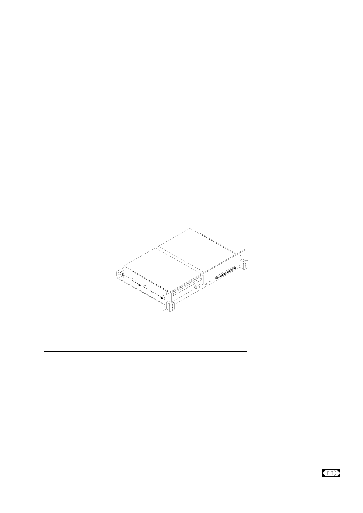
The BI-0316 provides 3.5” or smaller form factor devices in a convenient double Eurocard form factor.
The BI-0316 offers a full line of mass-storage subsystems that covers a variety of configurations with
corresponding performance, capacities, and prices.
For detailed information about the mounted drives on the BI-0316 see “Drive 1 Manual” on page F-1
and “Drive 2 Manual” on page G-1. For detailed information about the SCSI standards or the software
needed to operate SCSI based products see Table 1-2, “Related Documents” on page 1-3.
Figure 1-1 View of Module
1.2 Features
The BI-0316 integrates floptical and floppy disk drives, hard disk drives, DAT tape units, mini-cartridge
drives and rewritable optical disk drives into compact mass-storage subsystems.
1.2.1 SCSI Connectivity
The BI-0316 provides connectivity through SCSI-1, SCSI-2 and SCSI-3 interfaces:
•8-bit and 16-bit devices can be mixed on one module
•Single-Ended and Differential mode supported
•asynchronous and synchronous mode supported
•FAST and WIDE mode supported giving up to 20 Mbyte/sec transfer rate
Artisan Technology Group - Quality Instrumentation ... Guaranteed | (888) 88-SOURCE | www.artisantg.com

General Information BI-0316
Brand Innovators Page 1-2 Technical Manual
The drives on the BI-0316 are accessible via the 68 pin high density connector on the front or via the
SCSI bus signals which are available at the User Defined VMEbus P2 connector pins. A host VMEbus
module normally connects to the BI-0316 using a P-Cable at the front or by using a 68 (SCSI-3) or 50
(SCSI-2) wire flatcable at the rear of the module.
The BI-0316 is not memory mapped in the VMEbus address space, this in contrary to other products
which use the VMEbus for data transfers. The BI-0316 module does not occupy any address in the
VMEbus address space and does not rely on any signal (except power) to be available from the VME-
bus. This means that transferring data from or to the BI-0316 does not use any bandwidth of the VME-
bus backplane.
1.2.2 SCSI Daisy-Chaining
In order to support daisy-chain connections, the BI-0316 provides two shielded SCSI-3 device connec-
tors. One on the front and another at the VMEbus P2 connector.
Figure 1-2 SCSI Daisy-Chaining
Inside the BI-0316 the SCSI signals are looped from the front to the rear connector. The loop passes
the connection points of the drives on the BI-0316 in such a manner that stub lengths are minimized.
The length of the SCSI signals on the BI-0316 is 0.90 meter.
1.2.3 One Slot Solution
The BI-0316 subsystems have the standard VMEbus double Eurocard form factor and take either one,
two or three slots in a VMEbus rack depending on the height of the fitted drives.
1.2.4 VMEbus Signals
The VMEbus Interrupt Acknowledge and Bus Grant daisy-chain signals are routed on the BI-0316 to
facilitate Automatic-Daisy-Chain (ADC) backplanes.
The VMEbus ACFAIL* signal is used to warn the SCSI devices for a coming loss of power. The drives
can use this signal to prevent write interruptions within a data block. Note that this feature is only active
when the drives that are installed include this feature.
Artisan Technology Group - Quality Instrumentation ... Guaranteed | (888) 88-SOURCE | www.artisantg.com

BI-0316 General Information
Technical Manual Page 1-3 Brand Innovators
1.3 General Description
The 3.5” form factor devices supplied with a SCSI interface make it possible to design VMEbus mod-
ules which contain two of these devices in any combination.
The BI-0316 offers up to two drives, both with a full implementation of the SCSI bus on a single VME-
bus compatible module. Both drives have their own address on the SCSI bus and therefore operate
independently of each other. Drives with different widths and/or cabling options (SCSI-2 or SCSI-3) can
be mixed on the BI-0316. Both the Single-Ended and Differential option is supported.
The BI-0316 consists of a double Eurocard form factor base board with SCSI-2 and SCSI-3 type of con-
nectors. The base board contains no electronics except the light emitting diodes (LEDs) and ACFAIL*
buffers. On this board, 3.5” form factor devices are mounted which connect to the base board using
standard SCSI-2 or SCSI-3 cables. The LEDs are connected to the activity and fault signals of the
mounted devices. Rotary switches and jumper blocks are available for SCSI ID selection and enabling
of the termination of the SCSI bus signals.
1.4 Manual Updates
1.5 Related Documents
Table 1-1 Manual Updates
Revision Changes Additions Deletions
1.0
1.1 Editorial Changes
1.2 Position of jumper block and switches
Table 1-2 Related Documents
Document Title
Small Computer System Interface SCSI-1 X3T9 - I/O Interface X3.131-1986
Small Computer System Interface SCSI-2 X3T9 - I/O Interface X3.131-1993
SCSI-3 Parallel Interface SPI X3T9.2/855D Draft
SCSI-3 Interlocked Protocol SIP X3T9.2/856D Draft
SCSI-3 Architecture Model SAM X3T9.2/994D Draft
SCSI-3 Primary Commands SPC X3T9.2/995D Draft
SCSI-3 Block Commands SBC X3T9.2/996D Draft
SCSI-3 Stream Commands SSC X3T9.2/997D Draft
SCSI-3 Medium Changer Commands SMC X3T9.2/999D Draft
Artisan Technology Group - Quality Instrumentation ... Guaranteed | (888) 88-SOURCE | www.artisantg.com

General Information BI-0316
Brand Innovators Page 1-4 Technical Manual
Artisan Technology Group - Quality Instrumentation ... Guaranteed | (888) 88-SOURCE | www.artisantg.com
Technical Manual Page 2-1 Brand Innovators
Chapter 2 Functional Description
2.1 Introduction
This chapter provides an overview of the BI-0316 module. The block diagram of the module is shown in
“BI-0316 Block Diagram” on page A-1 and the schematics are shown in “Schematic Diagrams” on page
B-1.
2.2 Position Numbering
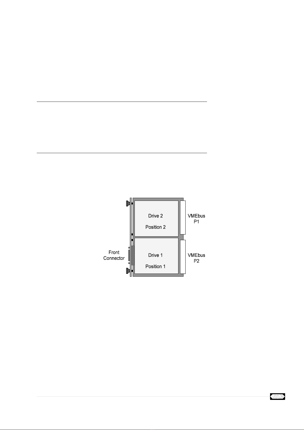
The BI-0316 holds up to two drives that are further referred to as drive 1 in position 1 and drive 2 in
position 2.
Figure 2-1 Position Numbering
This numbering scheme is used for identification of the devices and their position on the BI-0316.
Detailed information about the drives that are mounted on the BI-0316 is available in appendices
“Drive 1 Manual” on page F-1 and “Drive 2 Manual” on page G-1.
The numbering scheme has no relation to the SCSI IDs of the drives on the SCSI bus. The numbering
scheme indicates the physical order of the drives on the SCSI bus as observed from the VMEbus P2
connector to the front connector. When using the internal termination option of the drives, enable this
option on the last drive of the SCSI cable.
Artisan Technology Group - Quality Instrumentation ... Guaranteed | (888) 88-SOURCE | www.artisantg.com

Functional Description BI-0316
Brand Innovators Page 2-2 Technical Manual
2.3 SCSI Bus Technology
The interface used by the BI-0316 is the “Small Computer System Interface” (SCSI) bus standard. Dif-
ferent versions of this standard exist. A brief introduction to the standard is given in the following sec-
tions.
2.3.1 Overview
SCSI is a local I/O bus that can operate over a wide range of data rates. The primary objective of this
interface is to provide host computers with device independence within a class of devices. Thus, differ-
ent disk drives, tape drives, printers, optical media drives, and other devices can be added to a host
computer without requiring modifications to generic system hardware or software.
2.3.2 Data Transfer Options
The SCSI protocol is designed to provide an efficient peer-to-peer I/O bus with up to 8, 16, or 32
devices depending on the data path widths implemented, including one or more hosts. Data may be
transferred asynchronously at rates that depend primarily on device implementation and cable length.
Synchronous data transfers are supported at rates up to 10 megatransfers per second. Three data path
widths are allowed, 8-bit, 16-bit, and 32-bit. The corresponding maximum transfer rates are 10, 20, and
40 megabytes per second.
Data transfers are divided into three speed classes: asynchronous, slow, and fast. A
transfer period
specifies the minimum time allowed between the leading edges of successive REQ pulses and of suc-
cessive ACK pulses while using synchronous data transfers.
•Fast data transfers require a transfer period greater than 100 ns. and less than 200 ns. with a REQ/
ACK offset greater than zero. If a fast data transfer is agreed upon, fast timing shall be observed
even though the actual data transfer period is greater than or equal to 200 ns.
•Slow data transfers require a transfer period greater than or equal to 200 ns. with a REQ/ACK offset
greater than zero.
•Asynchronous information transfers require a REQ/ACK offset of zero. The transfer period does not
apply to these information transfers.
The BI-0316 supports all three classes.
2.3.3 Electrical Options
There are two electrical alternatives for the SCSI bus:
•Single-Ended and
•Differential.
Single-Ended and Differential devices are electrically incompatible and can not be mixed on the same
physical bus.
When the BI-0316 contains Single-Ended drives it can be used in a Single-Ended SCSI bus. When the
BI-0316 contains Differential drives it can be used in a Differential SCSI bus.
Artisan Technology Group - Quality Instrumentation ... Guaranteed | (888) 88-SOURCE | www.artisantg.com

BI-0316 Functional Description
Technical Manual Page 2-3 Brand Innovators
2.4 SCSI-2 and SCSI-3 Cabling Differences
The BI-0316 supports both the traditional SCSI (or SCSI-1) and SCSI-2 version as well as the new
SCSI-3 version. For reasons of clarity, when referring to the 8-bit SCSI, SCSI-1 or SCSI-2 versions, the
term SCSI-2 will be used.
2.4.1 SCSI-2 Cabling
SCSI-2 devices are daisy-chained using a common 50-conductor A-cable and, optionally, a 68-conduc-
tor B-cable. Both ends of each cable are terminated. The primary SCSI-2 bus carries an 8-bit data bus
and control signals. A primary SCSI-2 bus A-cable provides therefore an 8-bit data path. In systems
that employ the wide SCSI option, wide SCSI devices additionally connect to the B-cable. This second-
ary SCSI-2 bus carries an additional 24-bit data bus that, used in conjunction with a primary SCSI-2
bus, provides a 32-bit data path.
The BI-0316 supports the A-cable option of the SCSI-2 standard.
2.4.2 SCSI-3 Cabling
SCSI-3 devices are daisy-chained using a common 68-conductor P-cable and, optionally, a 68-conduc-
tor Q-cable. Both ends of each cable are terminated. The primary SCSI-3 bus carries a 16-bit data bus
and control signals. A primary SCSI-3 bus P-cable provides therefore a 16-bit data path. A secondary
SCSI-3 bus Q-cable carries an additional 16-bit bus that, used in conjunction with a primary SCSI-3
bus, provides a 32-bit data path.
The BI-0316 supports the P-cable option of the SCSI-3 standard.
2.5 SCSI Bus Connection Options
The BI-0316 can be connected to a SCSI bus initiator through the front or via the backplane connector.
When the host is connected to the front connector, the backplane connector can be used to terminate
or daisy-chain the SCSI bus signals. When the host is connected to the backplane connector, the front
connector can be used for termination or daisy-chaining of the SCSI bus signals.
At the front, a 68-pin high density connector (P3) with 2-56 jack screws for cable retention is used. This
connector complies to the SCSI-3 standard and connects directly to a Single-Ended or Differential bus
SCSI-3 P-cable.
The P3 connector contact assignments for Single-Ended use can be found in Table E-4, “P3, P5-P6
SCSI-3 Connectors (Single-Ended)” on page E-4. When the BI-0316 is used in a Differential bus the
contact assignments are given in Table E-5, “P3, P5-P6 SCSI-3 Connectors (Differential)” on page E-5.
2.5.1 SCSI-3 Option
This option uses the BI-0319 to connect to the SCSI bus signals on the VMEbus P2.
Artisan Technology Group - Quality Instrumentation ... Guaranteed | (888) 88-SOURCE | www.artisantg.com

Functional Description BI-0316
Brand Innovators Page 2-4 Technical Manual
Figure 2-2 SCSI-3 Daisy-Chain Option
This setup connects the BI-0316 to a 16-bit (WIDE) Single-Ended or Differential SCSI bus. Note that if
either the cable at the front or at the rear connector is not inserted, termination must be applied to this
connector. The following table contains a list of products to achieve this termination.
When the cable at the front has to connect to an 8-bit device, special care has to be given to the Upper
Byte termination. See “Mixing Buses Having Different Widths” on page 3-3.
2.5.2 SCSI-3 Mixed With SCSI-2 Option
This option uses the BI-0318 to connect to the SCSI bus signals on the VMEbus P2.
Figure 2-3 SCSI-3 to SCSI-2 Daisy-Chain Option
Table 2-1 Termination Products for 68-pin High Density Connector
Product Description Manufacturer
0-0869516-1 Amplimite .050 Series SCSI-3 Terminator Low Profile with Jack
Screws, Single-Ended 68 positions AMP
0-0869515-1 Amplimite .050 Series SCSI-3 Terminator Low Profile with Jack
Screws, Differential 68 positions AMP
Artisan Technology Group - Quality Instrumentation ... Guaranteed | (888) 88-SOURCE | www.artisantg.com

BI-0316 Functional Description
Technical Manual Page 2-5 Brand Innovators
This setup connects the BI-0316 to a 16-bit (WIDE) bus at the front and a 8-bit bus at the rear of the
module. Note that the upper byte signals must be terminated on the 16-bit to 8-bit adapter. This is
achieved by the on-board terminators of the BI-0318 module. These terminators are capable of termi-
nating Single-Ended as well as Differential SCSI buses.
See also “Mixing Buses Having Different Widths” on page 3-3.
2.6 SCSI Bus Backplane Connection Options
At the backplane different connection options are available:
•Option I: using a transition module on the VMEbus P2 connector
•Option II: using a flat cable connection on the VMEbus P2 connector
•Option III: using a special backplane layout to the VMEbus P2 connector
All three options can be used for 8-bit and 16-bit solutions in Single-Ended and Differential configura-
tions.
2.6.1 Option I. Transition Module
This is the most common and versatile option. It gives the capability to connect 8-bit and 16-bit cables
to the BI-0316. It gives also the capability to connect external terminators.
Table 2-2 Termination Products for 50-pin Low Density Connector
Product Description Manufacturer
0-0869576-1 Ampmodu Unshielded Receptacle SCSI-2 Terminator, Low Density,
Single-Ended, 50 positions AMP
0-0869041-1 Ampmodu Unshielded Receptacle SCSI-2 Terminator, Low Density,
Differential, 50 positions AMP
Artisan Technology Group - Quality Instrumentation ... Guaranteed | (888) 88-SOURCE | www.artisantg.com

Functional Description BI-0316
Brand Innovators Page 2-6 Technical Manual
Figure 2-4 Option I - Transition Module
The BI-0318 and BI-0319 are modules that fit on the VMEbus P2 connector of the BI-0316. They route
the SCSI signals of the VMEbus P2 connector to standard SCSI-2 and SCSI-3 connectors. The
BI-0318 and BI-0319 serve several functions:
•enable daisy-chaining of the SCSI-2 and SCSI-3 cables
•allowing external termination
•support mixing of 8- and 16-bit cables
The BI-0318 and BI-0319 Transition Modules can be used in VMEbus systems that are fitted with or
without a J2 backplane. In either case the BI-0318 and BI-0319 provide universal solutions with their
SCSI-2 and SCSI-3 type of connectors. See the Technical Manual of the BI-0318 and BI-0319 for the
installation details.
2.6.2 Option II. Flatcable Connection
This option can be used when the SCSI host module has a VMEbus P2 pin layout compatible with the
BI-0316.
Artisan Technology Group - Quality Instrumentation ... Guaranteed | (888) 88-SOURCE | www.artisantg.com
BI-0316 Functional Description
Technical Manual Page 2-7 Brand Innovators
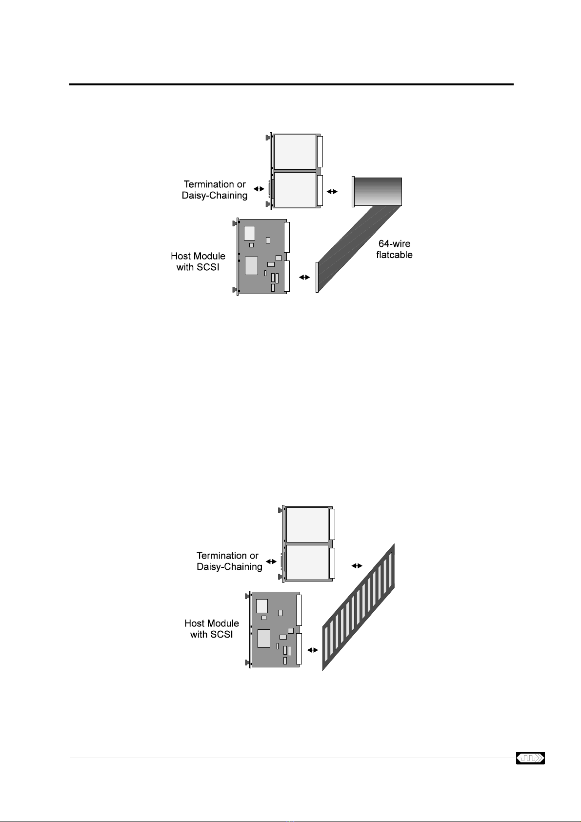
Figure 2-5 Option II - Flatcable Connection
A 64-wire flatcable connects corresponding pins on the VMEbus P2 connectors of the host module and
the BI-0316. The VMEbus P2 pin assignments of the BI-0316 are given in Table E-3, “VMEbus P2
Assignments (Differential)” on page E-3 and Table E-3, “VMEbus P2 Assignments (Differential)” on
page E-3.
2.6.3 Option III. Backplane Connection
This option can be used in dedicated systems where it is known which VMEbus modules are inserted in
the VMEbus backplane.
Figure 2-6 Option III - Backplane Connection
Artisan Technology Group - Quality Instrumentation ... Guaranteed | (888) 88-SOURCE | www.artisantg.com

Functional Description BI-0316
Brand Innovators Page 2-8 Technical Manual
A backplane is constructed which connects corresponding User Defined pins on the VMEbus P2 con-
nectors of the host module and the BI-0316. The VMEbus P2 pin assignments of the BI-0316 are given
in Table E-3, “VMEbus P2 Assignments (Differential)” on page E-3 and Table E-3, “VMEbus P2 Assign-
ments (Differential)” on page E-3.
2.7 Identification
A label is used to identify the drives on the BI-0316. The text on this label includes:
•board revision of the BI-0316
•board serial number
•type of drive(s) mounted
•serial number of the drive(s)
•SCSI ID number of the drive(s)
•termination options installed
Artisan Technology Group - Quality Instrumentation ... Guaranteed | (888) 88-SOURCE | www.artisantg.com
Technical Manual Page 3-1 Brand Innovators
Chapter 3 Installation Procedures
3.1 Introduction
This chapter provides the preparation and installation instructions for the BI-0316 module.
3.2 SCSI Bus ID Selection
A SCSI bus supports 8, 16 or 32 devices depending on the cable width used. Each device must have
an unique SCSI ID assigned. The SCSI IDs of the devices fitted can be selected using the switches
available on the BI-0316.
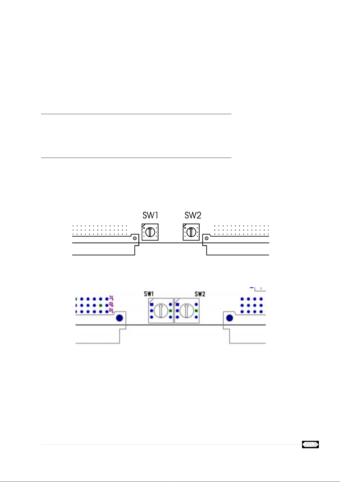
Figure 3-1 ID Selection PCB Version 1.0
Figure 3-2 ID Selection PCB Version 1.1
The device ID selection for each drive is accomplished using a hex rotary DIP switch. The SCSI ID of
drive 1 in position 1 is set with switch SW1, the SCSI ID of drive 2 is set with SW2. For 8-bit devices IDs
0 to 7 are used, for 16-bit devices IDs 0 to F are valid.
Artisan Technology Group - Quality Instrumentation ... Guaranteed | (888) 88-SOURCE | www.artisantg.com
Table of contents


