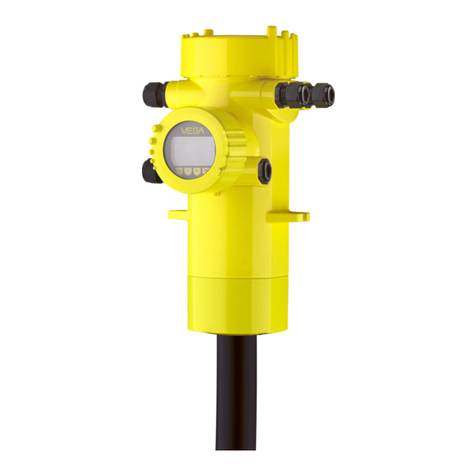
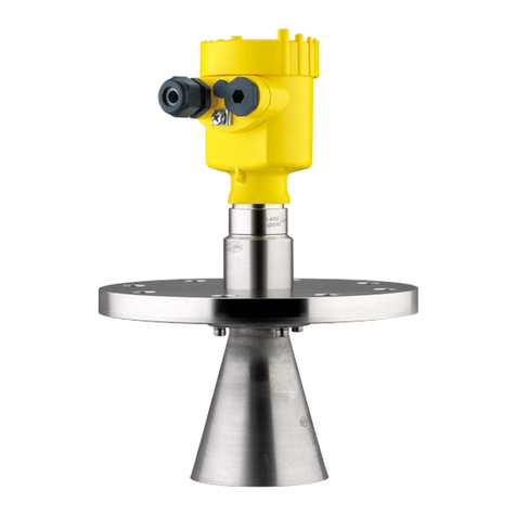
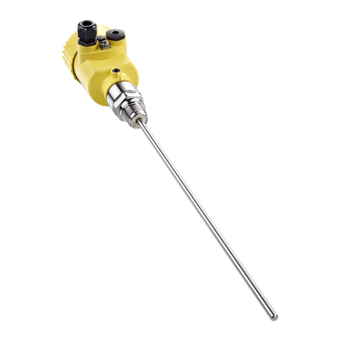
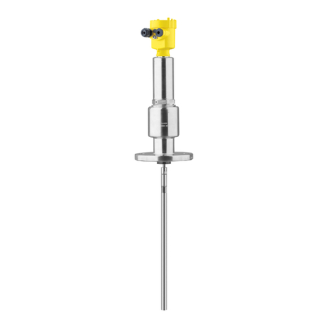
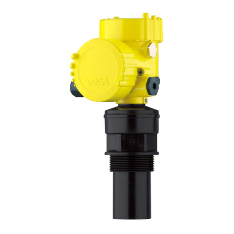
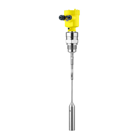
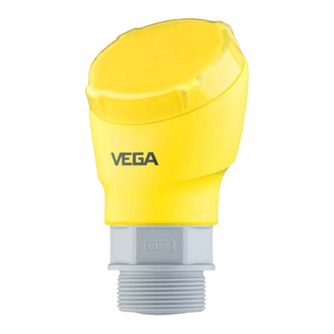
Vega VEGAPULS 69 User manual

Quick setup guide
Radar sensor for continuous level
measurement of bulk solids
VEGAPULS 69
4 … 20 mA/HART - four-wire
Document ID: 47255

2
Contents
VEGAPULS 69 • 4 … 20 mA/HART - four-wire
47255-EN-140801
Contents
1 For your safety
1.1 Authorised personnel ....................................................................................................... 3
1.2 Appropriate use................................................................................................................ 3
1.3 Warning about incorrect use............................................................................................. 3
1.4 General safety instructions............................................................................................... 3
1.5 CE conformity................................................................................................................... 4
1.6 NAMUR recommendations .............................................................................................. 4
1.7 Radio license for Europe .................................................................................................. 4
1.8 Environmental instructions ............................................................................................... 4
2 Product description
2.1 Conguration.................................................................................................................... 6
3 Mounting
3.1 Mounting preparations, mounting strap............................................................................ 8
3.2 Mounting instructions ....................................................................................................... 8
4 Connecting to power supply
4.1 Connection..................................................................................................................... 10
4.2 Wiring plan, double chamber housing ............................................................................ 11
5 Set up with the display and adjustment module
5.1 Insert display and adjustment module............................................................................ 13
5.2 Parameter adjustment - Quick setup .............................................................................. 13
5.3 Parameter adjustment - Extended adjustment................................................................ 15
6 Supplement
6.1 Technical data ................................................................................................................ 18
Information:
This quick setup guide enables quick setup and commissioning of
your instrument.
Youcanndsupplementaryinformationinthecorresponding,more
detailed Operating Instructions Manual as well as the Safety Manual
thatcomeswithinstrumentswithSILqualication.Thesemanualsare
available on the supplied DVD or in the download area of "www.vega.
com".
Operating instructions VEGAPULS 69 - 4 … 20 mA/HART - four-
wire: Document-ID 47249
Editing status of the quick setup guide: 2014-07-29

3
1 For your safety
VEGAPULS 69 • 4 … 20 mA/HART - four-wire
47255-EN-140801
1 For your safety
1.1 Authorised personnel
All operations described in this operating instructions manual must
be carried out only by trained specialist personnel authorised by the
plant operator.
During work on and with the device the required personal protective
equipment must always be worn.
1.2 Appropriate use
VEGAPULS 69 is a sensor for continuous level measurement.
Youcannddetailedinformationabouttheareaofapplicationin
chapter "Product description".
Operational reliability is ensured only if the instrument is properly
usedaccordingtothespecicationsintheoperatinginstructions
manual as well as possible supplementary instructions.
1.3 Warning about incorrect use
Inappropriate or incorrect use of the instrument can give rise to
application-specichazards,e.g.vesseloverllordamagetosystem
components through incorrect mounting or adjustment.
1.4 General safety instructions
This is a state-of-the-art instrument complying with all prevailing
regulations and guidelines. The instrument must only be operated in a
technicallyawlessandreliablecondition.Theoperatorisresponsible
for the trouble-free operation of the instrument.
During the entire duration of use, the user is obliged to determine the
compliance of the necessary occupational safety measures with the
current valid rules and regulations and also take note of new regula-
tions.
The safety instructions in this operating instructions manual, the na-
tional installation standards as well as the valid safety regulations and
accident prevention rules must be observed by the user.
For safety and warranty reasons, any invasive work on the device
beyond that described in the operating instructions manual may be
carried out only by personnel authorised by the manufacturer. Arbi-
traryconversionsormodicationsareexplicitlyforbidden.
The safety approval markings and safety tips on the device must also
be observed.
Depending on the instrument version, the emitting frequencies are in
the C or K band range. The low emitting frequencies are far below the
internationally approved limit values.When used correctly, there is no
danger to health.
4
1 For your safety
VEGAPULS 69 • 4 … 20 mA/HART - four-wire
47255-EN-140801
1.5 CE conformity
ThedevicefulllsthelegalrequirementsoftheapplicableECguide-
lines.ByaxingtheCEmarking,weconrmsuccessfultestingofthe
product.
YoucanndtheCECerticateofConformityinthedownloadsection
of our homepage.
1.6 NAMUR recommendations
NAMUR is the automation technology user association in the process
industry in Germany.The published NAMUR recommendations are
acceptedasthestandardineldinstrumentation.
ThedevicefulllstherequirementsofthefollowingNAMURrecom-
mendations:
• NE 21 – Electromagnetic compatibility of equipment
• NE 43 – Signal level for malfunction information from measuring
transducers
• NE53–Compatibilityofelddevicesanddisplay/adjustment
components
• NE107–Self-monitoringanddiagnosisofelddevices
For further information see www.namur.de.
1.7 Radio license for Europe
The instrument meets the LPR (Level Probing Radar) radio standard
EN 302729-1/2.
It is approved for unrestricted use inside and outside of closed ves-
sels in countries of the EU and EFTA that have implemented this
standard.
For operation outside of closed vessels, the following conditions must
befullled:
• Theinstallationmustbecarriedoutbytrainedqualiedpersonnel
• The instrument must be stationary mounted and the antenna
directed vertically downward
• The mounting location must be at least 4 km away from the radio
astronomy stations, unless special permission was granted by the
responsible national approval authority
• When installed within 4 to 40 km of a radio astronomy station,
the instrument must not be mounted higher than 15 m above the
ground.
Youcanndalistwiththerespectiveradioastronomystationsin
chapter "Supplement".
1.8 Environmental instructions
Protection of the environment is one of our most important duties.
That is why we have introduced an environment management system
with the goal of continuously improving company environmental pro-
tection.Theenvironmentmanagementsystemiscertiedaccording
to DIN EN ISO 14001.

5
1 For your safety
VEGAPULS 69 • 4 … 20 mA/HART - four-wire
47255-EN-140801
Pleasehelpusfulllthisobligationbyobservingtheenvironmental
instructions in this manual:
• Chapter "Packaging, transport and storage"
• Chapter "Disposal"

6
2 Product description
VEGAPULS 69 • 4 … 20 mA/HART - four-wire
47255-EN-140801
2 Product description
2.1 Conguration
Thetypelabelcontainsthemostimportantdataforidenticationand
use of the instrument:
2
1
14
15
16
17
13
12
11
5
3
6
4
7
8
9
10
Fig. 1: Layout of the type label (example)
1 Instrument type
2 Product code
3 Approvals
4 Power supply and signal output, electronics
5 Protection rating
6 Measuring range
7 Process and ambient temperature, process pressure
8 Material, wetted parts
9 Hardware and software version
10 Order number
11 Serial number of the instrument
12 Data-Matrix-Code for Smartphone-App
13 Symbol of the device protection class
14 ID numbers, instrument documentation
15 Reminder to observe the instrument documentation
16 NotiedauthorityforCEmarking
17 Approval directive
The type label contains the serial number of the instrument. With it
youcanndthefollowinginstrumentdataonourhomepage:
• Product code (HTML)
• Delivery date (HTML)
• Order-specicinstrumentfeatures(HTML)
• Operating instructions and quick setup guide at the time of ship-
ment (PDF)
• Order-specicsensordataforanelectronicsexchange(XML)
• Testcerticate(PDF)-optional
Go to www.vega.com, "VEGATools" and "Instrument search". Enter
the serial number.
Alternatively, you can access the data via your smartphone:
Type label
Serial number - Instru-
ment search

7
2 Product description
VEGAPULS 69 • 4 … 20 mA/HART - four-wire
47255-EN-140801
• Download the smartphone app "VEGATools" from the "Apple App
Store" or the "GooglePlayStore"
• Scan the Data Matrix code on the type label of the instrument or
• Enter the serial number manually in the app

8
3 Mounting
VEGAPULS 69 • 4 … 20 mA/HART - four-wire
47255-EN-140801
3 Mounting
3.1 Mounting preparations, mounting strap
The strap is supplied unassembled and must be screwed to the
sensor before setup with three hexagon screws M5 x 10 and spring
washers. Max. torque, see chapter "Technicaldata". Required tools:
Allenwrenchsize4.
There are two ways to screw the strap onto the sensor. Depending
on the selected version, the sensors can be swivelled in the strap as
follows:
• Single chamber housing
– Angleofinclination180°,innitelyvariable
– Angle of inclination in three steps 0°, 90° and 180°
• Double chamber housing
– Angleofinclination90°,innitelyvariable
– Angle of inclination in two steps 0° and 90°
3.2 Mounting instructions
Radar sensors for level measurement emit electromagnetic waves.
Thepolarizationisthedirectionoftheelectricalcomponentofthese
waves.
Thepolarizationdirectionismarkedbyanoseonthehousing,see
following drawing:
1
Fig. 2: Position of the polarisation
1 Nose for marking the direction of polarisation
Information:
Whenthehousingisrotated,thedirectionofpolarizationchanges
andhencetheinuenceofthefalseechoonthemeasuredvalue.
Please keep this in mind when mounting or making changes later.
Mount the sensor at least 200 mm (7.874 in) away from the vessel
wall.
Polarisation
Installation position

9
3 Mounting
VEGAPULS 69 • 4 … 20 mA/HART - four-wire
47255-EN-140801
200 mm
(7.87
")
Fig. 3: Mounting the radar sensor on the vessel top
If you cannot maintain this distance, you should carry out a false
signal storage during setup.This applies particularly if buildup on the
vessel wall is expected. In such cases, we recommend repeating the
false signal storage at a later date with existing buildup.

10
4 Connecting to power supply
VEGAPULS 69 • 4 … 20 mA/HART - four-wire
47255-EN-140801
4 Connecting to power supply
4.1 Connection
The voltage supply and signal output are connected via the spring-
loaded terminals in the housing.
Connection to the display and adjustment module or to the interface
adapter is carried out via contact pins in the housing.
Information:
The terminal block is pluggable and can be removed from the
electronics. To do this, lift the terminal block with a small screwdriver
and pull it out. When reinserting the terminal block, you should hear it
snap in.
Proceed as follows:
1. Unscrew the housing cover
2. Loosen compression nuts of the cable glands
3. Remove approx. 10 cm (4 in) of the cable mantle (signal output),
strip approx. 1 cm (0.4 in) insulation from the ends of the indi-
vidual wires
4. Insert the cable into the sensor through the cable entry
Fig. 4: Connection steps 5 and 6
5. Insert the wire ends into the terminals according to the wiring plan
Information:
Solidcoresaswellasexiblecoreswithwireendsleevesareinsert-
eddirectlyintotheterminalopenings.Incaseofexiblecoreswithout
end sleeves, press the terminal from above with a small screwdriver,
the terminal opening is then free. When the screwdriver is released,
the terminal closes again.
6. Check the hold of the wires in the terminals by lightly pulling on
them
Connection technology
Connection procedure

11
4 Connecting to power supply
VEGAPULS 69 • 4 … 20 mA/HART - four-wire
47255-EN-140801
7. Connect the screen to the internal ground terminal, connect the
outer ground terminal to potential equalisation in case of power
supply via low voltage
8. Connect the lead cable for power supply in the same way accord-
ing to the wiring plan, in addition connect the ground conductor to
the inner ground terminal when powered with mains voltage.
9. Tighten the compression nut of the cable glands.The seal ring
must completely encircle the cables
10. Screw the housing cover back on
Theelectricalconnectionisnished.
Information:
The terminal blocks are pluggable and can be removed from the
housing insert. To do this, lift the terminal block with a small screwdriv-
er and pull it out. When inserting the terminal block again, you should
hear it snap in.
4.2 Wiring plan, double chamber housing
The following illustrations apply to the non-Ex as well as to the Ex-d
version.
power supply
4...20mA
active
passive
common
IS GND
5
1
/L
/N
PE
2
+
( ) (-)
67 8
Fig. 5: Connection compartment with double chamber housing with mains
voltage
Terminal Function Polarity
1 Voltage supply +/L
2 Voltage supply -/N
5 4 … 20 mA output (active) +
6 4 … 20 mA output (passive) +
7 Mass - output -
8 Function ground with installa-
tion according to CSA
Connection compartment
with mains voltage

12
4 Connecting to power supply
VEGAPULS 69 • 4 … 20 mA/HART - four-wire
47255-EN-140801
power supply
4...20mA
active
passive
common
IS GND
5
1
/L
/N
2
+
( ) (-)
67 8
Fig. 6: Connection compartment with double chamber housing with low voltage
Terminal Function Polarity
1 Voltage supply +/L
2 Voltage supply -/N
5 4 … 20 mA output (active) +
6 4 … 20 mA output (passive) +
7 Mass - output -
8 Function ground with installa-
tion according to CSA
Connection compartment
with low voltage

13
5 Set up with the display and adjustment module
VEGAPULS 69 • 4 … 20 mA/HART - four-wire
47255-EN-140801
5 Set up with the display and adjustment
module
5.1 Insert display and adjustment module
The display and adjustment module can be inserted into the sensor
andremovedagainatanytime.Youcanchooseanyoneoffourdier-
ent positions - each displaced by 90°. It is not necessary to interrupt
the power supply.
Proceed as follows:
1. Unscrew the housing cover
2. Place the display and adjustment module on the electronics in the
desired position and turn it to the right until it snaps in.
3. Screw housing cover with inspection window tightly back on
Disassembly is carried out in reverse order.
The display and adjustment module is powered by the sensor, an ad-
ditional connection is not necessary.
Fig. 7: Insertion of the display and adjustment module with single chamber
housing
Note:
Ifyouintendtoretrottheinstrumentwithadisplayandadjustment
module for continuous measured value indication, a higher cover with
an inspection glass is required.
5.2 Parameter adjustment - Quick setup
To quickly and easily adapt the sensor to the application, select
the menu item "Quick setup" in the start graphic on the display and
adjustment module.

14
5 Set up with the display and adjustment module
VEGAPULS 69 • 4 … 20 mA/HART - four-wire
47255-EN-140801
Carry out the following steps in the below sequence.
Youcannd"Extendedadjustment" in the next sub-chapter.
1. Measurement loop name
Intherstmenuitemyouassignasuitablemeasurementloopname.
Permitted are names with max. 19 characters.
2. Medium
In this menu item you select the type of bulk solid.The selection com-
prisesdierentgranulatesizes.
3. Application/Vessel bottom
In this menu item you specify the application and the form of the ves-
sel bottom.
4. Vessel height/Measuring range
In this menu item you enter the height of the vessel and hence the
active measuring range.
5. Max. adjustment
In this menu item you carry out the max. adjustment.
Enterthemeasuringdistancefor100%lling.
6. Min. adjustment
In this menu item you carry out the min. adjustment.
Enterthemeasuringdistancefor0%lling.

15
5 Set up with the display and adjustment module
VEGAPULS 69 • 4 … 20 mA/HART - four-wire
47255-EN-140801
Thequicksetupisnished.
5.3 Parameter adjustment - Extended adjustment
Since the radar sensor is a distance measuring instrument, the
distance from the sensor to the product surface is measured. For
indication of the real level, an allocation of the measured distance to
the percentage height must be carried out.
To perform the adjustment, enter the distance with full and empty ves-
sel, see the following example:
2
1
3
100%
0%
1 m
(39.37
")
35 m
(1378
")
Fig. 8: Parameter adjustment example min./max. adjustment
1 Min. level = max. meas. distance
2 Max. level = min. meas. distance
3 Reference plane
If these values are not known, an adjustment with the distances of for
example 10 % and 90 % is possible. Starting point for these distance
specicationsisalwaysthesealsurfaceofthethreadorange.You
canndspecicationsofthereferenceplaneinchapter"Technical
data". By means of these settings, the real level will be calculated.
The real product level during this adjustment is not important, be-
cause the min./max. adjustment is always carried out without chang-
ing the product level.These settings can be made ahead of time
without the instrument having to be installed.
The function "Setup" allows the echo curve to be saved at the time of
setup.
Setup - Adjustment
Diagnostics - Echo curve
memory

16
5 Set up with the display and adjustment module
VEGAPULS 69 • 4 … 20 mA/HART - four-wire
47255-EN-140801
Information:
This is generally recommended, however, for use of the Asset
Management functions it is absolutely necessary. Saving should be
carried out with a very low level.
The function "Echocurvememory" allows up to ten individual echo
curves to be stored, for example to detect the measurement behav-
iourofthesensorindierentoperatingconditions.
With the adjustment software PACTware and the PC, the stored echo
curvescanbedisplayedwithhighresolutionandusedtorecognize
signal changes over time. In addition, the echo curve saved during
setup can also be displayed in the echo curve window and compared
with the actual echo curve.
Thefollowingcircumstancescauseinterferingreectionsandcan
inuencethemeasurement:
• High sockets
• Vessel installations such as struts
• Agitators
• Buildup or welded joints on vessel walls
Note:
A false signal suppression detects, marks and saves these false
signals so that they are no longer taken into account in the level
measurement.
This should be done with a low level so that all potential interfering
reectionscanbedetected.
Proceed as follows:
1. Select with [->] the menu item "False signal suppression" and
conrmwith[OK].
2. Conrmagainwith[OK].
3. Conrmagainwith[OK].
Additional adjustments -
False signal suppression

17
5 Set up with the display and adjustment module
VEGAPULS 69 • 4 … 20 mA/HART - four-wire
47255-EN-140801
4. Conrmagainwith[OK] and enter the actual distance from the
sensor to the product surface.
5. All interfering signals in this section are detected by the sensor
andstoredafterconrmingwith[OK].
Note:
Check the distance to the product surface, because if an incorrect
(too large) value is entered, the existing level will be saved as false
signal.Thellinglevelwouldthennolongerbedetectableinthisarea.
If a false signal suppression has already been created in the sensor,
the following menu window appears when selecting "False signal
suppression":
Delete: An already created false signal suppression will be com-
pletely deleted. This is useful if the saved false signal suppression no
longer matches the metrological conditions in the vessel.
Extend: is used to extend an already created false signal suppres-
sion.This is useful if a false signal suppression was carried out with
a too high level and not all false signals could be detected. When
selecting "Extend", the distance to the product surface of the created
false signal suppression is displayed. This value can now be changed
and the false signal suppression can be extended to this range.

18
6 Supplement
VEGAPULS 69 • 4 … 20 mA/HART - four-wire
47255-EN-140801
6 Supplement
6.1 Technical data
Electromechanical data - version IP 66/IP 67
Cable gland M20 x 1.5 or ½ NPT
Wire cross-section (spring-loaded terminals)
ƲMassive wire, stranded wire 0.2 … 2.5 mm² (AWG 24 … 14)
ƲStranded wire with end sleeve 0.2 … 1.5 mm² (AWG 24 … 16)
Voltage supply
Operating voltage
ƲVersion for low voltage 9.6…48VDC,20…42VAC,50/60Hz
ƲVersion for mains voltage 90…253VAC,50/60Hz
Reverse voltage protection Integrated
Max. power consumption 4 VA; 2.1 W

19
Notes
VEGAPULS 69 • 4 … 20 mA/HART - four-wire
47255-EN-140801

Printing date:
VEGA Grieshaber KG
Am Hohenstein 113
77761 Schiltach
Germany
47255-EN-140801
All statements concerning scope of delivery, application, practical use and operat-
ing conditions of the sensors and processing systems correspond to the information
available at the time of printing.
Subject to change without prior notice
© VEGA Grieshaber KG, Schiltach/Germany 2014
Phone +49 7836 50-0
Fax +49 7836 50-201
E-mail: [email protected]
www.vega.com
Other manuals for VEGAPULS 69
13
Table of contents
Other Vega Accessories manuals

Vega
Vega VEGASWING 61 User manual

Vega
Vega VEGAPULS 68 User manual

Vega
Vega POINTRAC 31 User manual

Vega
Vega POINTRAC 31 User manual

Vega
Vega VEGAPULS SR 68 User manual

Vega
Vega VEGAFLEX 86 User manual

Vega
Vega VEGAFLEX 65 User manual

Vega
Vega VEGAPULS 64 User manual

Vega
Vega VEGAPULS 66 User manual

Vega
Vega VEGAPULS 65 User manual

Vega
Vega VEGAPULS 68 User manual

Vega
Vega VEGABAR 18 User manual

Vega
Vega VEGAFLEX 86 User manual

Vega
Vega VEGAFLEX 67 User manual

Vega
Vega vegaflex 83 User manual

Vega
Vega VEGAPULS 6X User manual

Vega
Vega VEGABAR 81 User manual

Vega
Vega VEGAFLEX 82 User manual

Vega
Vega VEGAPULS WL 61 User manual

Vega
Vega VEGAFLEX 86 User manual