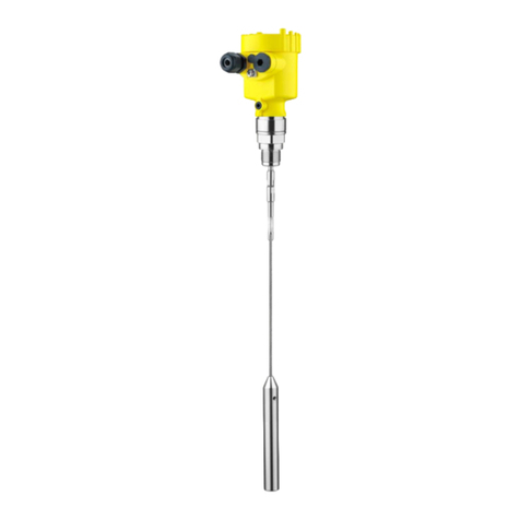
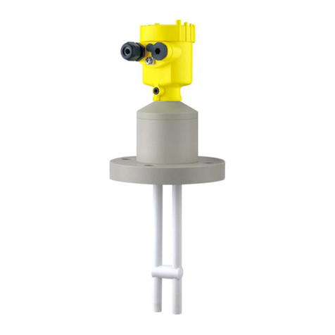
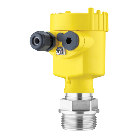
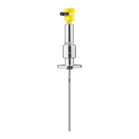
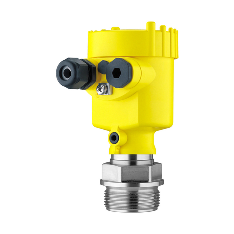
Vega VEGASON 62 User manual

Quick setup guide
Ultrasonic sensor for continuous level
measurement
VEGASON 62
Foundation Fieldbus
Document ID: 51862

2
Contents
VEGASON 62 • Foundation Fieldbus
51862-EN-210616
Contents
1 For your safety ......................................................................................................................... 3
1.1 Authorised personnel ....................................................................................................... 3
1.2 Appropriate use................................................................................................................ 3
1.3 Warning about incorrect use............................................................................................. 3
1.4 General safety instructions............................................................................................... 3
1.5 EU conformity................................................................................................................... 3
1.6 NAMUR recommendations .............................................................................................. 4
1.7 Environmental instructions ............................................................................................... 4
2 Product description ................................................................................................................. 5
2.1 Conguration.................................................................................................................... 5
3 Mounting................................................................................................................................... 6
3.1 Mounting instructions ....................................................................................................... 6
4 Connecting to power supply................................................................................................... 7
4.1 Connection procedure...................................................................................................... 7
4.2 Wiring plan, single chamber housing................................................................................ 8
4.3 Wiring plan, double chamber housing .............................................................................. 8
5 Set up with the display and adjustment module PLICSCOM .............................................. 9
5.1 Insert display and adjustment module.............................................................................. 9
5.2 Setup steps ...................................................................................................................... 9
5.3 Menu schematic............................................................................................................. 12
6 Set up with smartphone/tablet, PC/notebook via Bluetooth ............................................. 14
6.1 Preparations................................................................................................................... 14
6.2 Connecting..................................................................................................................... 15
6.3 Sensor parameter adjustment ........................................................................................ 16
7 Supplement ............................................................................................................................ 17
7.1 Technical data ................................................................................................................ 17
Information:
This quick setup guide enables quick setup and commissioning of
your instrument.
Youcanndsupplementaryinformationinthecorresponding,more
detailed Operating Instructions Manual as well as the Safety Manual
thatcomeswithinstrumentswithSILqualication.Thesemanualsare
available on our homepage.
Operating instructions VEGASON 62 - Foundation Fieldbus:
Document-ID 28791
Editing status of the quick setup guide: 2021-06-15

3
1 For your safety
VEGASON 62 • Foundation Fieldbus
51862-EN-210616
1 For your safety
1.1 Authorised personnel
All operations described in this documentation must be carried out
onlybytrained,qualiedpersonnelauthorisedbytheplantoperator.
During work on and with the device, the required personal protective
equipment must always be worn.
1.2 Appropriate use
VEGASON 62 is a sensor for continuous level measurement.
Youcannddetailedinformationabouttheareaofapplicationin
chapter " Product description".
Operational reliability is ensured only if the instrument is properly
usedaccordingtothespecicationsintheoperatinginstructions
manual as well as possible supplementary instructions.
1.3 Warning about incorrect use
Inappropriate or incorrect use of this product can give rise to applica-
tion-specichazards,e.g.vesseloverllthroughincorrectmounting
or adjustment. Damage to property and persons or environmental
contamination can result. Also, the protective characteristics of the
instrument can be impaired.
1.4 General safety instructions
This is a state-of-the-art instrument complying with all prevailing
regulations and directives. The instrument must only be operated in a
technicallyawlessandreliablecondition.Theoperatorisresponsi-
ble for the trouble-free operation of the instrument. When measuring
aggressive or corrosive media that can cause a dangerous situation
if the instrument malfunctions, the operator has to implement suitable
measures to make sure the instrument is functioning properly.
The safety instructions in this operating instructions manual, the na-
tional installation standards as well as the valid safety regulations and
accident prevention rules must be observed by the user.
For safety and warranty reasons, any invasive work on the device
beyond that described in the operating instructions manual may be
carried out only by personnel authorised by the manufacturer. Arbi-
traryconversionsormodicationsareexplicitlyforbidden.Forsafety
reasons,onlytheaccessoryspeciedbythemanufacturermustbe
used.
To avoid any danger, the safety approval markings and safety tips on
the device must also be observed.
1.5 EU conformity
ThedevicefullsthelegalrequirementsoftheapplicableEUdirec-
tives.ByaxingtheCEmarking,weconrmtheconformityofthe
instrument with these directives.
The EU conformity declaration can be found on our homepage.
4
1 For your safety
VEGASON 62 • Foundation Fieldbus
51862-EN-210616
1.6 NAMUR recommendations
NAMUR is the automation technology user association in the process
industry in Germany. The published NAMUR recommendations are
acceptedasthestandardineldinstrumentation.
ThedevicefullstherequirementsofthefollowingNAMURrecom-
mendations:
• NE 21 – Electromagnetic compatibility of equipment
• NE 43 – Signal level for fault information from measuring transduc-
ers
• NE53–Compatibilityofelddevicesanddisplay/adjustment
components
For further information see www.namur.de.
1.7 Environmental instructions
Protection of the environment is one of our most important duties.
That is why we have introduced an environment management system
with the goal of continuously improving company environmental pro-
tection.Theenvironmentmanagementsystemiscertiedaccording
to DIN EN ISO 14001.
Pleasehelpusfullthisobligationbyobservingtheenvironmental
instructions in this manual:
• Chapter " Packaging, transport and storage"
• Chapter " Disposal"

5
2 Product description
VEGASON 62 • Foundation Fieldbus
51862-EN-210616
2 Product description
2.1 Conguration
The type label contains the serial number of the instrument. With it
youcanndthefollowinginstrumentdataonourhomepage:
• Instrument type
• Article and serial number device
• Article number documentation
• Technicaldata:Approvals,processseal/processtemperature,
signal output, voltage supply, protection, protection class
• DatamatrixcodeforVEGAToolsapp
• SILidentication(withSILratingexworks)
Move to " www.vega.com"andenterinthesearcheldtheserial
number of your instrument.
Alternatively, you can access the data via your smartphone:
• Download the VEGA Tools app from the " Apple App Store" or the
" Google Play Store"
• ScantheDataMatrixcodeonthetypelabeloftheinstrumentor
• Enter the serial number manually in the app
Type label
Serial number

6
3 Mounting
VEGASON 62 • Foundation Fieldbus
51862-EN-210616
3 Mounting
3.1 Mounting instructions
The reference plane for the measuring range is the lower edge of the
transducer.
Make sure that a minimum distance from the reference plane - the
so-calleddeadzone,inwhichmeasurementisnotpossible-is
maintained.Theexactvalueofthedeadzoneisstatedinchapter"
Technical data".
1
2
Fig. 1: Minimum distance to the max. level
1 blocking distance
2 Reference plane
Mountthesensoratleast200mm(7.874in)awayfromthevessel
wall.
1
2
> 200 mm
Fig. 2: Mounting on round vessel tops
1 Reference plane
2 Vessel center or symmetry axis
Reference plane for
measuring range
Mounting

7
4 Connecting to power supply
VEGASON 62 • Foundation Fieldbus
51862-EN-210616
4 Connecting to power supply
4.1 Connection procedure
Proceed as follows:
1. Unscrew the housing lid
2. If a display and adjustment module is installed, remove it by turn-
ing it to the left
3. Loosen compression nut of the cable gland and remove blind
plug
4. Removeapprox.10cm(4in)ofthecablemantle,stripapprox.
1cm(0.4in)ofinsulationfromtheendsoftheindividualwires
5. Insert the cable into the sensor through the cable entry
6. Lifttheopeningleversoftheterminalswithascrewdriver(see
followingillustration)
7. Insert the wire ends into the open terminals according to the wir-
ing plan
Fig. 3: Connection steps 6 and 7
8. Press down the opening levers of the terminals, you will hear the
terminal spring closing
9. Check the hold of the wires in the terminals by lightly pulling on
them
10. Connect the shielding to the internal ground terminal, connect the
externalgroundterminaltopotentialequalisation
11. Tighten the compression nut of the cable entry gland. The seal
ring must completely encircle the cable
12. Screw the housing lid back on
Theelectricalconnectionisnished.

8
4 Connecting to power supply
VEGASON 62 • Foundation Fieldbus
51862-EN-210616
4.2 Wiring plan, single chamber housing
I2C
Display
1
12 5678
Fig. 4: Wiring plan - single chamber housing
1 Voltage supply, signal output
4.3 Wiring plan, double chamber housing
I2C
1
12
Fig. 5: Wiring plan - double chamber housing
1 Voltage supply, signal output
Wiring plan
Wiring plan

9
5 Set up with the display and adjustment module PLICSCOM
VEGASON 62 • Foundation Fieldbus
51862-EN-210616
5 Set up with the display and adjustment
module PLICSCOM
5.1 Insert display and adjustment module
The display and adjustment module can be inserted into the sensor
and removed again at any time. It is not necessary to interrupt the
voltage supply.
Proceed as follows:
1. Unscrew the housing lid
2. Place the display and adjustment module in the desired position
ontheelectronics(fourpositionsin90°osetcanbeselected)
and turn to the right until it clicks into place.
3. Screw housing lid with inspection window tightly back on
Disassembly is carried out in reverse order.
The display and adjustment module is powered by the sensor, an ad-
ditional connection is not necessary.
Fig. 6: Insert display and adjustment module in the single chamber housing
Note:
Ifyouintendtoretrottheinstrumentwithadisplayandadjustment
module for continuous measured value indication, a higher lid with an
inspection glass is required.
5.2 Setup steps
1. Go to the menu " Basic adjustment" via the display and adjust-
ment module.
Mount/dismount display
and adjustment module
Set parameters

10
5 Set up with the display and adjustment module PLICSCOM
VEGASON 62 • Foundation Fieldbus
51862-EN-210616
▶Basic adjustment
Display
Diagnostics
Service
Info
2. Carry out the adjustment in the menu items " Min. adjustment"
and " Max. adjustment".
Max.adjustment
100.00 %
=
1.000 m(d)
2.000m(d)
Min. adjustment
0.00 %
=
5.000 m(d)
4.000m(d)
3. Select in the menu item " Medium" the medium of your applica-
tion,forexample"Aqueous solution".
Medium
Liquid
4. Select in the menu item " Application" the vessel, the application
andthevesselform,forexample,"Storage tank".
Vessel shape
Storage tank
The sensor measures the distance from the sensor to the medium
surface. For indication of the real level, an allocation of the measured
distance to the percentage height must be carried out.
The actual level is then calculated on the basis of these entered
values. At the same time, the operating range of the sensor is limited
frommaximumrangetotherequestedrange.
Parameter adjustment

11
5 Set up with the display and adjustment module PLICSCOM
VEGASON 62 • Foundation Fieldbus
51862-EN-210616
100%
0%
0,25 m
(9.84
")
5 m
(196.9
")
2
1
3
Fig. 7: Parameterisation example, Min./max. adjustment
1 Min. level = max. distance (depending on the sensor)
2 Max.level=min.distance(nalvalueofthedeadzone,dependingonthe
sensor)
3 Reference plane
The actual product level during this adjustment is not important,
becausethemin./max.adjustmentisalwayscarriedoutwithout
changing the product level. These settings can be made ahead of
time without the instrument having to be installed.
Highnozzlesorvesselinstallations,suchase.g.strutsoragitatorsas
well as buildup and weld joints on the vessel walls, cause interfering
reectionswhichcanimpairthemeasurement.Afalseechostorage
detects and marks these false echoes, so that they are no longer
taken into account for the level measurement. A false echo memory
shouldbecreatedwithlowlevelsothatallpotentialinterferingreec-
tions will be detected.
False signal suppression
Change now?
Proceed as follows:
1. Move from the measured value display to the main menu by
pushing [OK].
2. Select the menu item " Service" with [->]andconrmwith[OK].
Now the menu item " False signal suppression" is displayed.
3. Conrm"False signal suppression - Change now" with [OK] and
select in the below menu " Create new". Enter the actual distance
from the sensor to the medium surface. All false signals in this
areaaredetectedbythesensorandsavedafterconrmingwith
[OK].
Service - False signal
suppression

12
5 Set up with the display and adjustment module PLICSCOM
VEGASON 62 • Foundation Fieldbus
51862-EN-210616
Note:
Check the distance to the medium surface, because if an incorrect
(toolarge)valueisentered,theexistinglevelwillbesavedasafalse
signal. The level would then no longer be detectable in this area.
5.3 Menu schematic
Information:
Depending on the version and application, the highlighted menu
windows may not always be available.
Basic adjustment
▶Basic adjustment 1
Display
Diagnostics
Service
Info
Min. adjustment 1.1
000.0 %
=
10.000 m(d)
1.245m(d)
Max.adjustment 1.2
100.0 %
=
0.000 m(d)
6.789m(d)
Medium 1.3
Liquid
Vessel shape 1.4
Storage tank
Damping 1.5
0 s
Linearisation curve 1.6
Linear
Display
Basic adjustment 2
▶Display
Diagnostics
Service
Info
Displayed value 2.1
AI-Out
Backlight 2.4
Switchedo►

13
5 Set up with the display and adjustment module PLICSCOM
VEGASON 62 • Foundation Fieldbus
51862-EN-210616
Diagnostics
Basic adjustment 3
Display
▶Diagnostics
Service
Info
Peak value indicator 3.1
Distancemin.:0.580m(d)
Dist.max.:16.785m(d)
T-max.:30.6°C
T-min.:4.5°C
Measurement reliability 3.2
36 dB
Device status
OK
Curve selection 3.3
Echo curve
Echo curve 3.4
Presentation of the echo
curve
Service
Basic adjustment 4
Display
Diagnostics
▶Service
Info
False signal suppression 4.1
Change now?
Extendedsetting 4.2
Fast
level change
(> 1 m/min.)
Simulation 4.3
Start simulation?
Reset 4.4
Reset now?
Unit of measurement 4.5
m(d)
Language 4.6
German
Copy sensor data 4.7
Copy sensor data?
PIN 4.8
Enable?
Info
Basic adjustment 5
Display
Diagnostics
Service
▶Info
Device ID 5.1
< max. 32 characters >
Sensor-TAG(PD_TAG)
< max. 32 characters >
Instrument type 5.2
VEGASON 6x
Serial number
12345678
Date of manufacture 5.3
24. March 2015
Software version
3.80
Last change using PC 5.4
10. April 2015
Sensor characteristics 5.5
Display now?

14
6Setupwithsmartphone/tablet,PC/notebookviaBluetooth
VEGASON 62 • Foundation Fieldbus
51862-EN-210616
6 Set up with smartphone/tablet, PC/
notebook via Bluetooth
6.1 Preparations
Make sure that the Bluetooth function of the display and adjustment
module is activated. For this, the switch on the bottom side must be
set to " On".
1
On
O
Fig. 8: Activate Bluetooth
1 Switch
On = Bluetooth active
O= Bluetoothnotactive
The security concept of Bluetooth operation absolutely requires that
the default setting of the sensor PIN be changed.This prevents unau-
thorizedaccesstothesensor.
The default setting of the sensor PIN is " 0000". First of all you have
to change the sensor PIN in the adjustment menu of the sensor, e.g.
to " 1111":
1. In the adjustment menu, go to " Service", " PIN":
Basic adjustment
Display
Diagnostics
▶Service
Info
PIN
Enable?
2. ChangesensorPINandconrmwith"OK":
PIN
0000
Activate Bluetooth
Change sensor PIN

15
6Setupwithsmartphone/tablet,PC/notebookviaBluetooth
VEGASON 62 • Foundation Fieldbus
51862-EN-210616
PIN
1111
PIN
Activated!
3. DeactivatesensorPINandconrmwith"OK":
PIN
Deactivate permanently?
PIN
0000
PIN
1111
PIN
Deactivated!
Sensoradjustmentviathedisplay/adjustmentmoduleorPACTware/
DTM by means of VEGACONNECT is thus released again. For ac-
cess(authentication)withBluetooth,thechangedPINisstilleective.
Note:
Bluetooth access can only be established if the current sensor PIN
diersfromthedefaultsetting"0000". It is possible both when the
PIN is deactivated and when it is activated.
6.2 Connecting
Smartphone/Tablet
Start the adjustment app and select the function "Setup". The smart-
phone/tabletsearchesautomaticallyforBluetooth-capableinstru-
ments in the area.
PC/Notebook
Start PACTware and the VEGA project assistant. Select the device
search via Bluetooth and start the search function. The device auto-
matically searches for Bluetooth-capable devices in the vicinity.
Preparations

16
6Setupwithsmartphone/tablet,PC/notebookviaBluetooth
VEGASON 62 • Foundation Fieldbus
51862-EN-210616
The message " Instrument search running" is displayed. All devices
found are listed in the operating window. The search is automatically
continued continuously.
Select in the device list the requested device.The message " Con-
necting" is displayed.
Fortherstconnection,theoperatingdeviceandthesensormust
authenticateeachother.Aftersuccessfulauthentication,thenextcon-
nection functions without authentication.
Forauthentication,enterinthenextmenuwindowthe4-digitsensor
PIN.
6.3 Sensor parameter adjustment
Thesensorparameterizationiscarriedoutviatheadjustmentappon
thesmartphone/tabletortheDTMonthePC/notebook.
Fig. 9: Example of an app view - Setup sensor adjustment
Connecting
Authenticate
App view

17
7 Supplement
VEGASON 62 • Foundation Fieldbus
51862-EN-210616
7 Supplement
7.1 Technical data
Note for approved instruments
The technical data in the respective safety instructions which are included in delivery are valid for
approvedinstruments(e.g.withExapproval).Thesedatacandierfromthedatalistedherein,for
exampleregardingtheprocessconditionsorthevoltagesupply.
All approval documents can be downloaded from our homepage.
Input variable
Measured variable distance between lower edge of the transducer and
medium surface
Measuring range
ƲLiquids upto8m(26.25ft)
ƲBulk solids upto3.5m(11.48ft)
Deadzone 0.4m(1.312ft)
Electromechanical data - version IP66/IP67 and IP66/IP68 (0.2 bar)
Options of the cable entry
ƲCable entry M20x1.5;½NPT
ƲCable gland M20x1.5;½NPT
ƲBlind plug M20x1.5;½NPT
ƲClosing cap ½NPT
Wirecross-section(spring-loadedterminals)
ƲMassive wire, stranded wire 0.2…2.5mm²(AWG24…14)
ƲStranded wire with end sleeve 0.2…1.5mm²(AWG24…16)
Voltage supply
Operating voltage 9 … 32 V DC
Operating voltage UBwith lighting
switched on
12 … 32 V DC
Powersupplyby/max.numberofsensors 32

18
Notes
VEGASON 62 • Foundation Fieldbus
51862-EN-210616

19
Notes
VEGASON 62 • Foundation Fieldbus
51862-EN-210616

Printing date:
VEGA Grieshaber KG
Am Hohenstein 113
77761 Schiltach
Germany
51862-EN-210616
All statements concerning scope of delivery, application, practical use and operat-
ing conditions of the sensors and processing systems correspond to the information
available at the time of printing.
Subject to change without prior notice
© VEGA Grieshaber KG, Schiltach/Germany 2021
Phone +49 7836 50-0
E-mail: [email protected]
www.vega.com
Other manuals for VEGASON 62
7
Table of contents
Other Vega Measuring Instrument manuals

Vega
Vega VEGABAR 81 User manual

Vega
Vega VEGASON 62 User manual

Vega
Vega VEGACAL 67 User manual

Vega
Vega VEGACAL 69 User manual

Vega
Vega VEGABAR 17 User manual

Vega
Vega VEGAPULS 69 User manual

Vega
Vega VEGAWAVE 62 User manual

Vega
Vega VEGATOR 631 Ex User manual

Vega
Vega VEGADIS 61 User manual

Vega
Vega ALT-5 User manual

Vega
Vega VEGAMIP R61 User manual

Vega
Vega VEGABAR 82 User manual

Vega
Vega VEGAPULS 6X User manual

Vega
Vega vegacap 62 User manual

Vega
Vega Bypass 72 Wiring diagram

Vega
Vega VEGAPULS 31 User manual

Vega
Vega VEGAPULS WL 61 User manual

Vega
Vega ASV-1 User manual

Vega
Vega VEGASWING 51 User manual

Vega
Vega VEGAVIB 62 Installation instructions