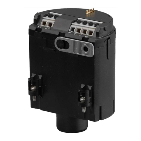
Vega VEGADIS 61 User manual

8888
8888
Operating Instructions
VEGADIS 61

2VEGADIS 61
27721-EN-021127
Contents
1 About this document
1.1 Function ..................................................... 4
1.2 Target group .............................................. 4
1.3 Symbolism used ....................................... 4
2 For your safety
2.1 Authorised personnel ................................ 6
2.2 Appropriate use......................................... 6
2.3 Warning about misuse ............................... 6
2.4 General safety instructions ........................ 6
2.5 CE conformity ............................................ 7
2.6 Safety instructions for Ex areas ................. 7
2.7 Environmentally responsible behaviour ..... 7
3 Product description
3.1 Configuration ............................................. 8
3.2 Principle of operation ................................. 9
3.3 Adjustment ................................................ 9
3.4 Storage and transport .............................. 10
4 Mounting ......................................................... 11

VEGADIS 61 3
27721-EN-021127
5 Connecting to the sensor
5.1 Prepare connection .................................. 13
5.2 Connection steps .................................... 14
5.3 Wiring plans ............................................ 16
6 Set-up with the indicating and adjustment
module PLICSCOM
6.1 Adjustment system and menu
structure .................................................. 17
6.2 Set-up procedure ..................................... 17
7 Maintenance and failure rectification
7.1 Maintenance ............................................ 18
7.2 Modify the instrument .............................. 18
7.3 Repair the instrument .............................. 19
8 Dismounting
8.1 Dismounting procedure ........................... 20
8.2 Disposal .................................................. 20
Supplement
Technical data .................................................. 21
Dimensions ....................................................... 23

4VEGADIS 61
27721-EN-021127
About this document
1 About this document
1.1 Function
This operating instructions manual has all the infor-
mation for quick set-up and safe operation of
VEGADIS 61. Please read this manual before you
start set-up.
1.2 Target group
All instructions described in this manual must be
carried out only by trained and authorized personnel.
The contents of this manual should be made avail-
able to this personnel and put into practice by them.
1.3 Symbolism used
Information, tip, note
This symbol indicates helpful additional information.
Caution
This symbol informs you of a possible and danger-
ous situation. Ignoring this cautionary note can impair
the person and/or the instrument.
Ex applications
This symbol indicates special instructions for Ex ap-
plications.

VEGADIS 61 5
27721-EN-021127
About this document
List
The dot set in front indicates a list with no implied
sequence.
Action
This arrow indicates a single action.
Sequence
Numbers set in front indicate successive steps in a
procedure.
•
1
–>

6VEGADIS 61
27721-EN-021127
For your safety
2 For your safety
2.1 Authorised personnel
All operations described in this operating instructions
manual must be carried out only by trained and au-
thorised personnel. For safety and warranty reasons,
any internal work on the instruments must be carried
out only by qualified VEGA personnel.
2.2 Appropriate use
VEGADIS 61 is an external indication and adjustment
unit for level and pressure transmitters of series 60.
2.3 Warning about misuse
Inappropriate or incorrect use of the instrument can
give rise to application-specific hazards, e.g. vessel
overfill or damage to system components through
incorrect mounting or setting.
2.4 General safety instructions
VEGADIS 61 is a high-tech instrument requiring the
strict observance of standard regulations and guide-
lines. The user must take note of the safety instruc-
tions in this operation instructions manual, the coun-
try-specific installation standards (e.g. the VDE
regulations in Germany) as well as prevailing safety
regulations and accident prevention rules.

VEGADIS 61 7
27721-EN-021127
2.5 CE conformity
VEGADIS 61 is in CE conformity with EMC (89/336/
EWG) and NSR (73/23/EWG) and fulfils the Namur
recommendations NE 21.
The conformity has been judged according to the
following standards:
EMC emission EN 61326: 1997
susceptibility EN 61326: 1997 + A1: 1998
NSR EN 61010: 2001
2.6 Safety instructions for Ex areas
In Ex applications, please note the Ex specific safety
instructions. They are a part of the operating instruc-
tions manual and are supplied with every instrument
with Ex approval.
2.7 Environmentally responsible behaviour
Protection of the environment is one of our most im-
portant duties. That is why we have introduced an
environment management system with the goal of
continuously improving company environmental pro-
tection. The environment management system is
certified acc. to DIN EN ISO 14001.
Please help us fulfil this obligation by observing the
environmental instructions in this manual:
– Section 3.4
– Section 8.2.
For your safety

8VEGADIS 61
27721-EN-021127
Scope of delivery
housing with
electronics
Housing cover with
indicating and ad-
justment module
PLICSCOM located
below
Mounting plate
Components
Product description
3 Product description
3.1 Configuration
The scope of delivery includes:
• VEGADIS 61 indication and adjustment unit
• Documentation
- this operating instructions manual
- Ex specific safety instructions (for Ex versions)
and other certificates, if required
VEGADIS 61 consists of the following components:
• mounting plate
• housing with electronics
• housing cover with indicating and adjustment
module PLICSCOM
The components are available in different versions.
Fig. 1:
Example of VEGADIS 61 with plastic housing and mounting
plate for wall mounting

VEGADIS 61 9
27721-EN-021127
3.2 Principle of operation
VEGADIS 61 is an external indication and adjustment
unit for the following VEGA sensors:
– Pressure transmitters VEGABAR 52, 53, 61, 64
and 65
- Level sensors VEGAFLEX 61, 62 and 65.
Product description
Area of application
Power supply
Fig. 2:
Connection of VEGADIS 61 to the sensor
VEGADIS 61 is connected to the sensor via a four-
wire, screened standard cable with a length of max.
25 m. An extra power supply is not required.
3.3 Adjustment
VEGADIS 61 can be adjusted via two different me-
dia:
• indicating and adjustment module PLICSCOM
• adjustment software PACT
ware
TM and PC.
The parameter adjustment is generally saved in the
sensor, or optionally in the PC when adjusting with
PACT
ware
TM and PC.

10 VEGADIS 61
27721-EN-021127
Product description
3.4 Storage and transport
Your instrument was protected by packaging during
transport. Its capacity to handle normal loads during
transport is assured by a test acc. to DIN 55439.
The packing consists of carton, is environment-
friendly and can be recycled. Dispose of the packing
material via specialised recycling companies.
Packing material carton/paper
Storage and transport temperature:-40 … 1)
rel. humidity: 20 … 85 %
Packing
Storage and transport tem-
perature
1) See Supplement, Technical data, Ambient conditions

VEGADIS 61 11
27721-EN-021127
Mounting
Select installation position
4 Mounting
VEGADIS 61 functions in any installation position. It
is mounted either on a mounting plate or rail 35 x 7.5
acc. to DIN EN 50 022. The housing can be rotated
330° without using any tools.
Fig. 3:
Bore pattern for mounting on the mounting plate
85
62
7
12

12 VEGADIS 61
27721-EN-021127
Mounting
Protection against mois-
ture Protect VEGADIS against moisture.
–> lead the connection cable located in front of the
cable entry downwards.
Fig. 4:
Measures against moisture ingress
Rain and condensed water can thus drain off, espe-
cially in outdoor installations, in rooms where humid-
ity is expected (e.g. caused by cleaning processes)
or on cooled or heated vessels.

VEGADIS 61 13
27721-EN-021127
Connecting to the sensor
5 Connecting to the sensor
5.1 Prepare connection
Always observe the following safety instructions:
• Connect only in the complete absence of line volt-
age
In hazardous areas, always observe the appropriate
guidelines and type approval certificates of the sen-
sors and VEGADIS 61.
VEGADIS 61 is connected with standard four-wire
cable to the sensor. An outer diameter of 5 ... 9 mm
ensures the seal effect of the cable entry.
We recommend screened cable.
In Ex applications, please observe the appropriate
installation guidelines.
Note safety instructions
Note safety instructions of
Ex applications
Select connection cable
Select connection
cable for Ex appli-
cations

14 VEGADIS 61
27721-EN-021127
Connecting to the sensor
5.2 Connection steps
Please proceed as follows:
1 Remove the cover of the housing
2 Turn PLICSCOM to the left and take it off
Fig. 5:
Dismounting the indicating and adjustment module PLICSCOM
3 Loosen the compression nut of the cable entry
4 Dismantle the connection cable approx. 10 cm,
remove approx. 1 cm insulation from core wires
5 Push the cable through the cable entry into
VEGADIS 61
6 Raise the opening lug of the terminals with a
screwdriver
7 Insert the core ends into the open terminals ac-
cording to the wiring diagram

VEGADIS 61 15
27721-EN-021127
Connecting to the sensor
Fig. 6:
Connection steps 6 and 7
8 Push down the opening lugs of the terminals, the
terminal spring closes clearly audibly
9 Check the hold of the wires in the terminals by
slightly pulling on them
10 Connect screen to ground terminals
11 Connect the ground terminals on the housing ex-
terior to a low-impedance ground
12 Tighten the compression nut of the cable entry
firmly, the seal ring must completely encircle the
cable
13 Press PLICSCOM lightly onto the electronics and
turn it to the right until it snaps in
14 Screw on the housing cover.
The electrical connection is finished.

16 VEGADIS 61
27721-EN-021127
Connecting to the sensor
Display
Typ:
DS61
Com.
567 8
Contact spring for indicating and
adjustment module PLICSCOM
Earth terminal1)
Plug connection for
VEGACONNECT 3
with adapter cable
Spring terminal for con-
nection of the sensor
1) Connect cable screen here,
connect ground terminal on
the housing exterior to
ground as prescribed. The
two terminals are galvani-
cally connected.
2) Earthing at both ends in
case of non-Ex. For Ex we
recommend earthing at one
side acc. to EN 60079-14.
Top view of the electronics
and connection compart-
ment
Wiring plan
Display
5678
PC with
PACT
ware
TM
e.g. VEGABAR
Plug con-
nection
VEGADIS 61 VEGABAR/
VEGAFLEX
Terminal 5 –> Terminal 5
Terminal 6 –> Terminal 6
Terminal 7 –> Terminal 7
Terminal 8 –> Terminal 8
2)
5.3 Wiring plans
Fig. 7:
Top view of the combined electronics and connection compart-
ment

VEGADIS 61 17
27721-EN-021127
ESC OK
1.1
6 Set-up with the indicating and adjustment module PLICSCOM
6.1 Adjustment system and menu structure
Set-up with the indicating and adjustment module PLICSCOM
LC display for indi-
cation of
- measured value
- menu item
- parameter
[ESC]:
- Interrupt entry
- Jump to the next
higher menu
[+]:
- Change the
value of the
parameter
[–>]:
- Menu
- Menu item
- Select parameter
[OK]:
- Jump to the menu
range
- Confirm parameter
- Edit parameter
- Save the value
Indicating and adjustment
elements
Adjustment system
Indication of the
menu items
You adjust the sensor via the four keys and the dis-
play of the A/B module. The functions are shown in
the above illustration. 15. minutes after you have
pushed a key for the last time, an automatic reset to
the measured value will be triggered.
6.2 Set-up procedure
The set-up and adjustment of the sensors must be
carried out according to the operating instructions of
the sensor and the indicating and adjustment module
PLICSCOM.

18 VEGADIS 61
27721-EN-021127
PLICSCOM mounting or
dismounting
7 Maintenance and failure rectification
7.1 Maintenance
In normal operation, VEGADIS 61 is completely main-
tenance-free.
7.2 Modify the instrument
PLICSCOM can be mounted on or dismounted from
VEGADIS 61 at any time. The power supply must not
be interrupted.
For dismounting, please proceed as follows:
1 Remove housing cover
2 Turn PLICSCOM slightly to the left and remove
Maintenance and failure rectification
Fig. 9:
Dismounting of indicating and adjustment module
PLICSCOM
3 Screw the housing cover back on tightly.
Mounting is carried out in reverse order.

VEGADIS 61 19
27721-EN-021127
Maintenance and failure rectification
7.3 Repair the instrument
If it is necessary to repair VEGADIS 61, please send
the instrument to the following address:
VEGA Grieshaber KG
Repair Department
Am Hohenstein 113
77761 Schiltach
Germany

20 VEGADIS 61
27721-EN-021127
Dismounting
8 Dismounting
8.1 Dismounting procedure
Please observe the chapters 4 "Mounting" and 5
"Connecting to the sensor" and carry out the steps in
reverse order.
8.2 Disposal
VEGADIS 61 consists of materials which can be recy-
cled by specialised recycling companies. We have
purposely designed the electronic modules to be
easily separable. Mark the instrument as scrap and
dispose of it according to government regulations.
If you cannot dispose of the instrument properly,
please contact us concerning disposal methods or
return.
Other manuals for VEGADIS 61
2
Table of contents
Other Vega Measuring Instrument manuals

Vega
Vega VEGABAR 82 User manual

Vega
Vega VEGAPULS 61 User manual

Vega
Vega VEGADIS 371 Ex User manual

Vega
Vega VEGACAL 69 User manual

Vega
Vega vegacap 62 User manual

Vega
Vega WEIGHTRAC 31 User manual

Vega
Vega plicscom User manual

Vega
Vega ALT-5 User manual

Vega
Vega VEGABAR 38 User manual

Vega
Vega EL 4 User manual

Vega
Vega VEGABAR 52 User manual

Vega
Vega VEGAFLEX 81 User manual

Vega
Vega VEGAVIB 61 User manual

Vega
Vega POINTRAC 31 User manual

Vega
Vega VEGAMIP R62 User manual

Vega
Vega vegaflex 83 User manual

Vega
Vega vegaflex 83 User manual

Vega
Vega VEGACAL 62 User manual

Vega
Vega VEGACAL 69 User manual

Vega
Vega VEGAMIP R61 User manual