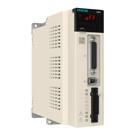
Veichi SD700 series User manual

1
前言
感谢您选用 SD700 系列交流伺服驱动器。
SD700 系列交流伺服驱动器为我司通用型高性能伺服驱动器,该产品采用了一系列先进电机控制算法并搭
配24 位高精度编码器,具有控制精度高,跟踪响应快,调试简单方便等特点,可满足中高端通用伺服应用需求
的功能及性能。产品内置点位控制功能、电子凸轮、RS485 接口、CANopen 接口、16 位模拟量输入等丰富的应
用扩展功能,可为机床、电子设备、机器人、纺织、包装等应用提供高可靠性、高性价比解决方案。
本手册为随机资料,仅提供安全注意事项、安装与配线、功能码简表、故障码解释及对策、监控参数说明
等方面的介绍,详细的功能注解及应用说明请参见 SD700 系列产品说明书或咨询本公司。本手册是您正确使用,
发挥其优越性能和安全运行的基本指导文件,请务必详细阅读和妥善保存,并请交给本产品的最终使用者。
在使用过程中,如遇有疑难问题或特殊要求,请随时与本公司(办事处)或经销商联络,也可直接同本公
司客户服务中心联系,我们将竭诚为您服务。
本公司一直致力于产品的持续优化,因此本系列产品及相关资料有可能优化或变动,亦有变动的可能,如
有变动恕不另行通知。由此带来的不便,敬请谅解。

2
安全注意事项
为保证安全、合理的使用本产品,请在完全理解本手册所述的安全注意事项后再使用该产品。
操作资质
本产品必需由经过培训的专业人员进行操作。并且,作业人员必须经过专业的技能培训,熟悉设备的安装、
接线、运行和维护保养,并正确应对使用中出现的各种紧急情况。
安全指导
警告标志是为了您的安全而提出的,是防止操作人员受到伤害、本产品及关联系统受到损坏而采取的措施;
请在使用前仔细阅读本手册,并严格按照本手册中的安全规则和警告标志进行操作。
正确的运输、存放、安装、以及细心的操作和维护、对于伺服系统安全运行是至关重要的。在运输和
存放期间要保证伺服系统不致遭受冲击和振动,也必须保证存放在干燥、无腐蚀气体、无导电粉尘和
环境温度小于 60℃的地方。
本产品带有危险电压,而且它所控制的是带有潜在危险的运动机构,如果不遵守规定或不按本手册的
要求进行操作,可能会导致人身伤亡、本产品及关联系统损坏。
请勿在电源接通的状态下进行接线作业,否则有触电致人死亡的危险;在接线、检查、维护等作业时,
请切断所有关联设备的电源,并确认主回路直流电压已经下降到安全水平,等 10 分钟后再进行相关
作业。
电源线、电机线、控制线都必须紧固连接,接地端子必须可靠接地,且接地电阻小于 10Ω。
人体静电会严重损坏内部敏感器件,进行相关作业前,请遵守静电防止措施(ESD)规定的措施和方
法,否则可能损坏伺服系统。
由于伺服系统输出电压是脉冲波形,如果输出侧安装有改善功率因数的电容或防雷用压敏电阻等器件,
务必请拆除或者改装在伺服系统输入侧。
伺服系统输出侧不要加断路器和接触器等开关器件(如果必须在输出侧接开关器件,则在控制上必须
保证开关动作时伺服系统的输出电流为零)。
无论故障出现在控制设备的什么地方,都有可能致停产及重大事故。因此,请采取必要的外部保护措
施或备用装置。
本产品只能按照制造商规定的用途来使用,未经许可不得使用在有关应急、救援、船舶、医疗、航空、
核设施等特殊领域。
本产品的维护保养只能由本公司或得到本公司授权许可的专业人员进行,未经授权改装、使用非本公
司可的配件,可能导致产品故障。维护中,任何有缺陷的器件都必须及时更换。

3
1. 安装与配线
1.1 主回路端子尺寸
L1
L2
L3
L1C
L2C
B1
B2
B3
U
V
W
+
/
主回路接口
针号 信号名称 功能
1 L1 主回路电源输入
请根据铭牌确定输入电源为 220V 还是 400V
220V 机型:200V ~ 240V, -15% ~ +10% 50Hz /60Hz
400V 机型:380V ~ 440V, -15% ~ +10% 50Hz /60Hz
注:“L3”端子,SD700-1R1A、1R8A、3R3A 机型为单相输入无该引脚
2 L2
3 L3
4 L1C 控制电源输入
电源输入要求同 L1、L2、L3
5 L2C
6 B1/+ 再生电阻器连接端子
SD700-1R1A、1R8A、3R3A 再生制动能力不足时,在 B1/+与 B2 之间连接外置再
生电阻器;其他型号拆下 B2-B3 之间的短接线或短接片,在 B1/+与 B2 之间连
接外置再生电阻器,外置再生电阻器请另行购买。
“B1/+”端子,可用于共直流母线正电源端子
注:“B3”端子,SD700-1R1A、1R8A、3R3A 机型无该引脚
7 B2
8 B3
9 - “-”端子,可用于共直流母线负电源端子
10 U
连接电机的 U、V、W 相 11 V
12 W
13 安全地

4
1.2 CN1 控制端子

5
1.3 CN2 编码器信号端子
B
A
1
23
4
5
6
78
9
信号定义 A端针脚号 B端针脚号
编码器电源+5V
编码器电源0V
串行数据SD+
串行数据SD-
PE(屏蔽层)
1
2
5
6
1
2
5
6
铁壳 7
引脚定义
绝对值编码器电池BAT+ 33
绝对值编码器电池BAT- 4 4
1
3
5
2
4
6
注意:使用多圈绝对值编码器时,请注意电池、串行数据的连接。
1.4 电机电源端子
视图
A
3
4
12
黄绿
PE
W
V
U蓝
棕
红
A
信号定义 线芯颜色A端脚位号
40/60/80法兰电机动力线定义
U蓝
2
V棕
3
W红
4
PE 黄绿
1
PE
W
V
U
A
A D
CB
信号定义 线芯颜色A端脚位号
100/110/130/180/220法兰动力线定义
U蓝
A
V棕
B
W红
C
PE 黄绿D

6
1.5 CN6A/CN6B 总线通讯端子
引脚8
引脚1
引脚8
引脚1
CN6A
CN6B
根据机型不同,该端口的定义不同,使用时需确认机型后再对应该接口的定义。
字段标识位为 P:脉冲型;S:标准型;C:CANopen 总线型。
CN6A/CN6B 接口定义
针号 信号名称 功能 针号 信号名称 功能
1 CANH CAN 数据+ 6 -
2 CANL CAN 数据- 7 GND 485 信号地
3 CANG CAN 信号地 8 - -
4 485- 485 数据- 外壳 屏蔽 屏蔽
5 485+ 485 数据+
字段标识位为 M:MECHATROLINK‐II 总线型。
CN6A/CN6B 接口定义
针号 信号名称 功能
1 SRD+ M-II 数据+ 6 - -
2 SRD- M-II 数据- 7 - -
3 - - 8 - -
4 - - 外壳 屏蔽 屏蔽
5 - -
字段标识位为 N:EtherCAT 总线型;L:MECHATROLINK‐III 总线型。
CN6A/CN6B 接口定义
针号 信号名称 功能 针号 信号名称 功能
1 TX+ 数据发送+ 6 RX- 数据接收-
2 TX- 数据发送- 7 - -

7
3 RX+ 数据接收+ 8 - -
4 - - 外壳 屏蔽 屏蔽
5 - -
关于同时使用多台驱动器,级联方式为 CN6A 进,CN6B 出,级联电缆请在 50cm 以下,最后一台的 CN6B
需视情况连接终端电阻。
1.6 输出端口注意事项
ALM-等
输出端子
ALM+等输
出端子
SO1+等
输出端子
SO1-等
输出端子
接感性负载时,务必安
装此续流二极管
各输出端子的最大带载能
力:30V,50mA。
RY
各输出端子的最大带载能
力:30V,50mA。
接阻性负载时,该限流电阻阻
值大小需保证回路电流小于
50
mA
伺服驱动器
1.7 抱闸配线
伺服电机用于垂直轴的场合时,抱闸可用来在伺服驱动器断电时阻止或保持重物下落的速度。电磁制动器
的连接如下图:
+
-
RY
12V~24V
SO1-
SO1+
伺服驱动器
+
-
电机
制
动
绕
组
浪涌吸
收器
保险
(5A)
制动绕组
专用电源
急停
按钮
RY
DC24V
注意:
制动器绕组必须使用专用24V电源,切勿与控制电源或
RY 继电器线圈电源共用。
电磁制动器用 24V 电源需用户另备一专用电源,切勿与控制信号用电源共用;
图中 为继电器线圈,请注意二极管的方向;
电磁制动器用于保持用,不可用于通常的停车;
虽然电磁制动器有阻止或保持重物下落的作用,但请用户同时要在外部安装
RY

8
1.8 位置控制的连接示例
PL1
PL2
PL3
GND
PAO
/PAO
PBO
/PBO
PCO
/PCO
PULS
/PULS
/SIGN
SIGN
CLR
/CLR
OCP
OCS
差分指令
脉冲输入
(最大4Mp ps)
集电极
开路
编码器分频
脉冲输出A相
编码器分频
脉冲输出B相
编码器分频
脉冲输出C相
指令脉冲用集电
极开路电源输出
信号接地
CN1
7
8
11
12
15
14 适用的线性接收
器T.I.公司制
SN75ALS175型
或MC3486的同
等产品
连接器
壳体
FG 屏蔽线与连接器壳体相连。
框架接地
光电耦合器输出
最大容许电压:
DC 30V
最大容许电流:
DC 50mA
*1
33
35
36
19
20
3
34
13
18
1
25
26
27
28
29
30
31
32
①24V电源,内置限流电阻
②12V~24V电源,且需外置
限流电阻
V
DC
24V
PULS
/PULS
SIGN
/SIGN
V
DC
12V
~24V
R
R
V
DC
12V
24V
R电阻参数
2kΩ,1/4W
1kΩ,1/4W V
DC
-1.5
R+68 ≈10mA
OCP
/PULS
OCS
/SIGN
16
17
绝对值编码器用
电池
3.2V~4.5V
*3
21
22
BAT(+ )
BAT(-)
*2
/S-ON
/P-CON
P-OT
N-OT
/ALM-RST
顺控输入信号
用电源输入
伺服ON输入
(信号ON时伺服ON)
P动作指令输入
(信号ON时P动作)
警报复位输入
(信号ON时复位)
转矩限制选择
(根据转矩限制方式配
置)
40
41
42
43
44
45
+24V 47
+24VIN
39
/INHIBIT
38
/C-SEL
指令脉冲禁止输入
(信号ON时指令脉
冲禁有 止输入有效)
控制方式切换输入
(信号ON时控制方式
切换有效)
*2. DC24V电源请用户自备。此外,DC24V电源请使用双重绝缘或强化绝缘的设备。
*3. 在使用绝对值编码器时连接。但在使用带电池单元的编码器电缆时,请勿连接CN1-21、CN1-22引脚。
*4. 输出信号请务必通过线性接收器接收。
(注)使用24V制动器时, DC24V电源请务必与输入输出信号(CN1)用等电源分开,另行准备其它电源。电源通用时,会导致输入输出信号
的误动作。
*1. 表示双股绞合屏蔽线。
+15V
/TLC
正向限位输入
(OFF时限位)
负向限位输入
(OFF时限位)
OCC 24
ALM+
ALM- 伺服报警输出
报警时OFF
/S-RD Y+
/S-RD Y-
伺服准备就绪输
出(可接收/SON
信号状态时ON)
/COIN+
/COIN-
定位完成
(定位完成时ON)
/V-CM P+
/V-CM P-
速度一致
(速度一致时ON)

9
1.9 速度控制的连接示例
ALM+
ALM-
GND
PAO
/PAO
PBO
/PBO
PCO
/PCO
编码器分频
脉冲输出A相
编码器分频
脉冲输出B相
编码器分频
脉冲输出C相
信号接地
伺服报警输出
报警时OFF
CN1
连接器
壳体
FG 屏蔽线 与连接 器壳体相 连。
框架接地
光电耦合器输出
最大容许电压:
DC 30V
最大容许电流:
DC 50mA
33
35
36
19
20
34
1
25
26
27
28
29
30
31
32
5
9
10
6
V-REF
SG
SG
T-REF
速度指令输入
(最大输入电压:±10V) D/A
D/A
A/D
外部转矩限制/转矩前馈
(最大输入电压:±10V)
*2
/S-ON
/P-CON
P-OT
N-OT
/ALM-RST
/TLC
顺控输入信号
用电源输入
伺服ON输入
(信号ON时伺服ON)
P动作指令输入
(信号ON时P动作)
警报复位输入
(信号ON时复位)
转矩限制选择
(根据转 矩限制方式配
置)
40
41
42
43
44
45
+24V 47
+24VIN
39
/ZCLAMP
38
/C-SEL
零位固定输入
(信号ON零位固定有效)
控制方式切换输入
(信号ON时控制方式
切换有效)
绝对值编码器用
电池
3.2V~4.5V
*3
21
22
BAT(+)
BAT(-)
*2. DC24V电源请用户自备。此外,DC24V电源请使用双重绝缘或强化绝缘的设备。
*3. 在使用绝对值编码器时连接。但在使用带电池单元的编码器电缆时,请勿连接CN1-21、CN1-22引脚。
*4. 输出信号请务必通过 线性接收器接收。
(注)使用24V制动器时, DC24V电源请务必与输入输出信号(CN1)用等电源分开,另行准备其它电源。电源通用时,会导致入输出
信号的误动作。
*1. 表示双股绞合屏蔽线。
正向限位输入
(OFF时限位)
负向限位输入
(OFF时限位)
适用的线性接收
器T.I.公司制
SN75AL S175型
或MC3486的同
等产品
/S-RDY+
/S-RDY-
伺服准备就绪输
出(可接收/SON
信号状态时ON)
/COIN+
/COIN-
定位完成
(定位完成时ON)
/V-CMP+
/V-CMP-
速度一致
(速度一致时ON)

10
1.10 转矩控制的连接示例
ALM+
ALM-
GND
PAO
/PAO
PBO
/PBO
PCO
/PCO
编码器分频
脉冲输出A相
编码器分频
脉冲输出B相
编码器分频
脉冲输出C相
信号接地
伺服报警输出
报警时OFF
CN1
连接器
壳体
FG 屏蔽线与连接器壳体相连。
框架接地
光电耦合器输出
最大容许电压:
DC 30V
最大容许电流:
DC 50mA
33
35
36
19
20
34
1
25
26
27
28
29
30
31
32
5
9
10
6
V-REF
SG
SG
T-REF
外部速度限制
(最大输入电压:±10V) D/A
D/A
A/D
转矩指令输入
(最大输入电压:±10V)
绝对值编码器用
电池
3.2V~4.5V
*3
21
22
BAT(+)
BAT(-)
*1. 表示双股绞合屏蔽线。
*2
/S-ON
/P-CON
P-OT
N-OT
/ALM-RST
/TLC
顺控输入信号
用电源输入
伺服ON输入
(信号ON时伺服ON)
P动作指令输入
(信号ON时P动作)
正向限位输入
(OFF时限位)
警报复位输入
(信号ON时复位)
转矩限制选择
(根据转矩限制方式配
置)
负向限位输入
(OFF时限位)
40
41
42
43
44
45
+24V 47
+24VIN
38
/C-SEL
控制方式切换输入
(信号ON时控制方式
切换有效)
适用的线性接收
器T.I.公司制
SN75AL S17 5型
或MC3486的同
等产品
/S-RDY+
/S-RDY-
伺服准备就绪输
出(可接收/SON
信号状态时ON)
/COIN+
/COIN-
定位完成
(定位完成时ON)
/V-CMP+
/V-CMP-
速度一致
(速度一致时ON)
*2. DC24V电源请用户自备。此外,DC24V电源请使用双重绝缘或强化绝缘的设备。
*3. 在使用绝对值编码器时连接。但在使用带电池单元的编码器电缆时,请勿连接CN1-21、CN1-22引脚。
*4. 输出信号请务必通过线性接收器接收。
(注)使用24V制动器时, DC24V电源请务必与输入输出信号(CN1)用等电源分开,另行准备其它电源。电源通用时,会导致入输出
信号的误动作。

11
装 箱 明 细
序号 名 称 数量
11伺服驱动器
简易说明书
SCSI插头(50P)
接线端子手柄
请您在打开包装时,认真清点包装箱内物品是否
与装箱明细上所列一致,如有疑义请与经销商联系。
7P插拔式接线端子头
3P插拔式接线端子头
备注:4、5、6项配件仅以下机型配备
SD700-1R1A-**/SD700-1R8A-**/SD700-3R3A-**
1
1
1
1
1
2
3
4
5
6

12
Preface
Thanks for using SD700 series AC servo drive.
VEICHI SD700 series is the general purpose high performance servo drive which adopts a series of advanced
motor control algorithm and 24-bit high precision encoder, featuring high control precision, fast tracking response,
simple and convenient debugging to meet the function and performance requirements in high-end general purpose
servo applications. Rich application functions such as built-in point control function, electronic cam, RS485 interface,
CANopen interface and 16-bit analog input can provide high reliability and high cost performance solutions for
machine tools, electronic equipment, robots, textile applications, packaging industry and etc.
This manual is delivered with equipment and only introduces safety precautions, installation and wiring, function
code table, fault diagnoses and processing, monitoring parameters and etc. For detailed function explanations and
application specifications please refer to SD700 series product instructions or consult VEICHI company. As it is the
basic guide for proper use and safe operation, please carefully read and keep it and be sure to handle it to end users.
If any problems or special requirements, please feel free to contact our company, dealers or the customer service
center, we will provide dedicated service for you.
This manual is subject to change without notice, thanks for your kind support.

13
Safety Precautions
For safety concerns, please fully understand the safety requirements and cautions before using.
Operational Qualifications
Only professional trained people are allowed to operate the equipment. In addition, operators must undergo
professional skills training and be familiar with the equipment installation, wiring, operation and maintenance, and can
correctly respond to various emergency situations in use.
Safety Guidance
Safety regulations and warning signs come for your security. They are measures to prevent the operator and
machine system from damage. Please carefully read this manual before using and strictly observe the regulations
and warning signs while operating.
Correct transport, store, installation and careful operation and maintenance are important for servo system
safe operation. In transport and store process, make sure the servo system is free from impact and
vibration. It must be stored where is dry without corrosive air and conductive dust, and the temperature
bust be lower than 60℃.
This product carries dangerous voltage and controls driver machine with potential danger. If you don’t abide
by the regulations or requirements in this manual, there is danger of body injury even death and machine
damage.
Do not wire while the power is connected. Otherwise, there is danger of death for electric shock. Before wiring,
inspection, maintenance, please cut off power supply of all related equipment and ensure main DC
voltage in safe range. And operate it after 10 minutes.
Power line, motor line and control line must be fastened. The grounding terminal must be grounded reliably
and the grounding resistance is less than 10Ω.
Human body static electricity will seriously damage the internal sensitive devices. Before operation, please
follow ESD measures, or there will be danger of servo system damage.
As the output voltage of servo system is pulse weave, if components such as capacitors for improving power
factor or pressure-sensitive resistances for anti-thunder are installed at the output side, please dismantle
them or change to input side.

14
1. Installation and Wiring
1.1 Main Circuit Terminal Size
L1
L2
L3
L1C
L2C
B1
B2
B3
U
V
W
+
/
Main circuit interface
Pins number Sign name Function
1 L1
Power input of the main circuit
Please determine whether the input power is 220V or 400V according to the nameplate
220V models: 200V ~ 240V, -15% ~ +10% 50Hz / 60Hz
2 L2 400V models: 380V ~ 440V, -15% ~ +10% 50Hz / 60Hz
3 L3
Note: "L3" terminal, SD700-1R1A, 1R8A, 3R3A models are single-phase inputs without
this pin
4 L1C Control power input
5 L2C Power input requirements same with L1, L2, L3
6 B1/+
Regenerative resistor connection terminal
SD700-1R1A, 1R8A, 3R3A. When regenerative braking capacity is insufficient, connect
an external regenerative resistor between B1 / + and B2. Other models remove short
wiring or short connection between B2 and B3. Connect an external regenerative resistor
between B1 / + and B2. The external regenerative resistor need be purchased separately.
7 B2 "B1 / +" terminals can be used for common DC bus positive power supply terminals.
8 B3 Note: "B3" terminal, SD700-1R1A, 1R8A, 3R3A models without this pin.
9 - "-" terminal can be used for common DC bus negative power supply terminals
10 U
Connect the U, V, W phase of the motor
11 V
12 W
13
Safe ground

15
1.2 CN1 Control Terminal
No.1
No.2
No.24
No.25
No.26
No.27
No.49
No.50
The appearance seen from the
arrow direction is shown below.
2SG Sig nal
gr o und
4SEN
R eq ui rem en t
input of
en cod er
absolu te d at a
(SE N)
6SG
Si g nal g r oun d
Signal ground
3PL1
OC power
outp ut of
command
pu l se
5V-REF
Sp ee d
command
input
1SG
8/PULS
Pulse
command
input
7PULS
Pulse
command
input
10 SG
Sig nal
gr o und
9T-REF
Torque
command
input
27
/SO2+
(TGON
+)
General
sequence
control output 2
29
/SO3+
(S-
RDY+)
General
sequence
control
outp ut 3
31 AL M+ Servo alarm
ou tp ut
33 PA O
A pha se of
en cod er
pu l se d i visi o n
ou tp ut
35 PB O
B pha se of
encoder pulse
division output
26
/SO1-
(V-CMP-
)
General
sequence
control output 2
28 /SO2-
(TGON-)
General
sequence
control
ou tp ut 2
30
/SO3-
(S-RDY-
)
General
sequence
control output 3
32 AL M- Servo alarm
ou tp ut
34 /PAO
A pha se of
en cod er p uls e
di vis ion ou tpu t
11 SI GN Sig n
command
input
36 /PB O
B pha se of
encoder pulse
division output
12 /SIGN
Sig n
command
input
37 ST O R ese rve d
13 PL2
OC power
outp ut of
command
pulse
14 /CLR
C lear a nce
input of
po si ti on
deviatio n
39 /SI9
Gene ral
sequence
control input 9
/SI838
General
sequence
control input
8
16 OCP
OC power
input of
command
pulse
CLR
Clearance
input of
position
de vi ati o n
15 41
/SI3
(P-
CON)
General
sequence
control input 3
40 /SI0
(/S-ON)
General
sequence
control input 0
18 PL 3
OC power
ou tp ut o f
command
pu l se
17 OCS
OC input of
pu l se
di rec t io n 43 /SI2
(N-OT)
General
sequence
control input 2
42 /SI1
(P-OT)
General
sequence
control input 1
20 /PCO
C ph ase of
en cod er
pulse division
ou tp ut
19 PCO
C phase of
en cod er
pu l se d ivisi o n
ou tp ut
44
/SI4
(/ALM-
RTS)
General
sequence
control input 4
22 BA T-
Batte ry(-) of
ab sol u te
en cod er
21 BA T+
Ba tte ry( +) of
ab s olu te
en cod er
45 /SI5
(/P-CL)
General
sequence
control input 5
46 /SI6
(/N-CL)
General
sequence
control input 6
47 +24VIN
Power input of
sequence
control input
signal
48 PS O
Position output
of ab s olut e
en cod er
24 OCS
OC input of
pu l se
clearance
23 OCZ
OC o utput of
Z phase
pu l se d ivisi o n 49 /PS O
Position
outp ut of
ab sol u te
en cod er
25
/SO1+
(V-
CMP+)
General
sequence
control output
1
50 TH
Overheat
pr o tecti o n
input of linear
motor

16
1.3 CN2 Encoder Signal Terminal
B
A
1
23
4
5
6
7
8
9
21
43
65
Sign Define AEnd Pins Number BEnd Pins Number
+5V
0V
SD+
SD-
PE(Shield
)
1
2
5
6
1
2
5
6
Iron Shell 7
Pins Define
BAT+ 3 3
BAT- 4 4
Note: When using multi-turn absolute encoder, please pay attention to the connection of battery and serial data.
1.4 Motor Power Terminal

17
PE
W
V
U
A
A D
CB
信号定义 线芯颜色A端脚位号
100/110/130/180/220法兰动力线定义
U蓝
A
V棕
B
W红
C
PE 黄绿D
1.5 CN6A/CN6B Bus Communication Terminal
The definition of this port is different according to different models. When you use it, you need to confirm the model
and then correspond to the definition of the interface.

18
The field identification bits are P: pulse type; S: standard type; C: CANopen bus type.
CN6A/CN6B Port definition
Pin No. Signal name Function Pin No. Signal name Function
1 CANH CAN data+ 6 -
2 CANL CAN data- 7 GND 485 signal ground
3 CANG CAN signal ground 8 - -
4 485- 485 data- shell shield shield
5 485+ 485 data+
The field identification bit is M: MECHATROLINK-II bus type.
CN6A/CN6B Port definition
Pin No. Signal name Function Pin No. Signal name Function
1 SRD+ M-II data+ 6 - -
2 SRD- M-II data- 7 - -
3 - - 8 - -
4 - - shell shield shield
5 - -
The field identification bit is N: EtherCAT bus type; L: MECHATROLINK-III bus type.
CN6A/CN6B Port definition
Pin No. Signal name Function Pin No. Signal name Function
1 TX+
Data transmission
+ 6 RX- Data reception -
2 TX-
Data transmission
- 7 - -
3 RX+ Data reception + 8 - -
4 - - shell shield shield
5 - -
Regarding the use of multiple drivers at the same time, the cascading method is CN6A in, CN6B out, the
cascading cable should be under 50cm, and the last CN6B needs to be connected to the terminating resistor as
appropriate.

19
=
1.6 Output Port Attentions
1.7 Brake Wiring
When servo motor is used for vertical axis situations, the brake can be used to prevent or keep the falling speed of
heavy loads when servo drive is in power off state. Wiring diagram of electromagnetic brake is shown as below:
Electromagnetic brake must be provided with a dedicated 24V power supply, be prohibited to share
power source with control signal;
means relay coil, please note the diode direction;
Electromagnetic brakes are for holding and can not be used for normal parking;
Though electromagnetic brake has function to prevent or keep heavy objects from falling, external
braking devices are still necessary.
RY

20
1.8 Position Control Wiring Diagram
COIN+
COIN-
TGON+
TGON-
S-RDY+
S-RDY-
ALM+
ALM-
PL1
PL2
PL3
SG
PAO
/PAO
PBO
/PBO
PCO
/PCO
/PSO
PSO
PULS
/PULS
/SIGN
SIGN
CLR
/CLR
OCP
OCS
Differential
comma nd puls e
input
(Max 4Mpps)
OC
Aphase of encoder
pulsedivisionoutput
Bphase of encoder
pulsedivisionoutput
C phase of encoder
pulsedivisionoutput
Position output of
absolute encode
OC power output of
commandpulse
Signal ground
Position finished
(ON while finished)
Speed detection output
(ON while above setting
value)
Servo ready output (ON
whilereceivable /SON)
Servo alarm output
OFF while alarm
CN1
7
8
11
12
15
14 Linear receiver:
SN75ALS175or
MC3486of T.I.
company
Connector shell
FG shields are connectedwith
connector shell.
Frame ground
Max voltage
of optocoupler
output:
DC 30V
Max current:
DC 50mA
*1
33
35
36
19
20
48
49
3
34
13
18
1
25
26
27
28
29
30
31
32
①24V power, with built-in
current limitingresistance
②12V~24Vpower ,with
external current limiting
resistance
V
DC
24V
PULS
/PULS
SIGN
/SIGN
V
DC
12V
~24V
R
R
V
DC
12V
24V
R
2kΩ,1W/4W
1kΩ,1W/4W
V
DC
-1.5
R+68 ≈10mA
OCP
/PULS
OCS
/SIGN
16
17
Battery of absolute
encoder
2.8V~4.5V
*3
21
22 BAT(+)
BAT(-)
*2
/S-ON
/P-CON
/P-OT
/N-OT
/ALM-RST
/P-CL
/N-CL
Powerinput of sequence
control input signal
Servo ON input
(ServoON whilesignal ON)
Poperationcommandinput
(P operates while ON)
Forbid FWD driving input
(Forbiddrivingwhile OFF)
Alarmreset input
(Reset while ON)
FWDside
External torque limit input
(Limit whileON)
Forbid REV driving input
(Forbiddrivingwhile OFF)
REV side
External torque limit input
(Limit whileON)
40
41
42
43
44
45
46
+24V 47
+24VIN
39
/ZCLAMP
38
/C-SEL
37
/STO
Forbidcommandpulseinput
(ValidwhileON)
Control modeswitch input
(ValidwhileON)
*2. DC24VpoweR should be prepared by user. And double insulation orreinforced insulation equipments should beused for DC24Vpower.
*3. Connected whileusingabsolute encoder. But never connect backupbattery while using encoder cables with battery unit.
*4. Output signalshould be received by linear receiver.
(Note)While using 24VBRaker,DC24Vpower should be separatedFormthe power for input andoutput signal(CN1).Pleaseprepare otherpower individually, otherwise,
there maybe misoperation of input and output signal whilepower on.
*1. is twisted shields;
+15V
Other manuals for SD700 series
3
This manual suits for next models
3
Table of contents
Other Veichi Servo Drive manuals
Popular Servo Drive manuals by other brands

Applied Motion Products
Applied Motion Products MDX Series Quick setup guide

Welcon
Welcon WEC-D048/08-FS0025-E Hardware manual

turck
turck IM72-11Ex/L manual

Panasonic
Panasonic MINAS A6 Series quick start guide

Kollmorgen
Kollmorgen AKD manual

Control Techniques
Control Techniques Unidrive Regen installation guide