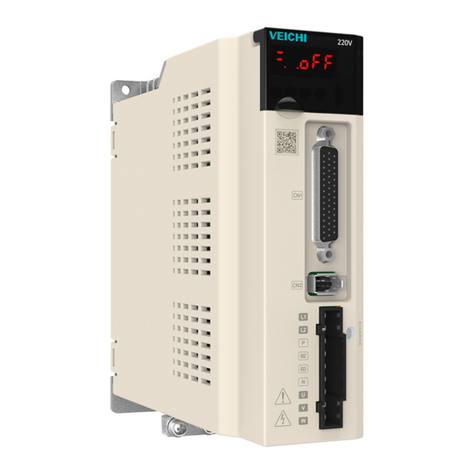
Veichi SD780 Series User manual

Contents
I SD780 Series Servo Technical Manual
Contents
Contents ............................................................................................................................................I
1 Abstract..........................................................................................................................................1
1.1 Series Introduction..............................................................................................................1
1.2 Name of Each Part of the Servo Drive................................................................................1
1.3 Basic Information of Servo Drive ........................................................................................2
1.3.1 Installation Dimensions ...........................................................................................2
1.3.2 Installation Way.......................................................................................................4
1.3.3 Specifications and Electric Parameters .................................................................. 5
1.3.4 Basic specifications.................................................................................................6
1.4 System Diagram................................................................................................................10
1.5 System Configuration Examples....................................................................................... 11
1.6 Drive Name .......................................................................................................................12
1.7 Maintenance and Inspection of Servo Drive .....................................................................13
1.7.1 Inspection of Servo Motor .....................................................................................13
1.7.2 Inspection of Servo Drive......................................................................................13
1.7.3 Approximate Standards for Changing Internal Parts of Servo Drive.....................14
1.8 Motor Name ...................................................................................................................... 15
1.9 Dimension of Motors .........................................................................................................16
2 Panel Operation ..........................................................................................................................22
2.1 Basic Operation.................................................................................................................22
2.1.1 Keys’ Names and Functions of the Panel Operator.............................................. 22
2.1.2 Functions Switch ...................................................................................................23
2.1.3 Status Display .......................................................................................................23
2.2 Operations of Auxiliary Functions (Fn group) ...................................................................24
2.3 Operations of Parameter (Pn Group)................................................................................24
2.4 Operations of Monitoring Display Un Group .....................................................................25
3 Wiring and Connections.............................................................................................................26
3.1 Main Circuit Wiring............................................................................................................26
3.1.1 Terminals Description............................................................................................ 26
3.1.2 Wiring Diagram .....................................................................................................27
3.2 Motor Power Line Connection...........................................................................................30
3.3 CN2 Encoder Connection .................................................................................................32
3.4 CN7 USD communication terminal (connect to host machine).........................................33
3.5 Connection of CN6A and CN6B Communication Terminal ...............................................34
3.6 CN5 Full Closed Loop Port ...............................................................................................35
3.7 Definition of CN1 Terminal ................................................................................................36
3.8 Digital Input Signal ............................................................................................................ 37
3.8.1 Input Signal Descriptions ......................................................................................37
3.8.2 Input Signal Configuration.....................................................................................38
3.8.3 Confirming the Input Status...................................................................................40
3.9 Digital Output Signal .........................................................................................................41
3.9.1 Output Signal Descriptions....................................................................................41
3.9.2 Output Signal Configuration..................................................................................42
3.9.3 Confirming the Output Status................................................................................42

Contents
II SD780 Series Servo Technical Manual
3.10 Connection with the Upper Device..................................................................................43
3.10.1 Analog Input Circuit 3..........................................................................................43
3.10.2 Position Instruction Input Circuit..........................................................................43
3.10.3 Sequence Control Input Circuit ...........................................................................47
3.10.4 Sequence Output Loop .......................................................................................47
3.11 Position Control Wiring Diagram .....................................................................................49
3.12 Speed Control Wiring Diagram .......................................................................................50
3.13 Torque Control Wiring Diagram.......................................................................................51
3.14 Regenerative Resistor Connection .................................................................................52
3.14.1 Connection of Regenerative Resistors ...............................................................52
3.14.2 Selection of Regenerative Resistor.....................................................................52
3.15 Noise and High Harmonic Countermeasures .................................................................53
4 Trial operation .............................................................................................................................54
4.1 Inspections and Notes before Trail Operation ..................................................................54
4.1.1 Conditions of the Servo Motor...............................................................................54
4.1.2 Conditions of the Servo Drive ...............................................................................54
4.1.3 Installation .............................................................................................................54
4.2 JOG trail operation............................................................................................................ 54
5 Operation.....................................................................................................................................55
5.1 Basic Functions.................................................................................................................55
5.1.1 Quick Guide...........................................................................................................55
5.1.2 Servo Enable and Over-Travel Setting .................................................................55
5.1.3 Motor Rotation Direction .......................................................................................57
5.1.4 Stop Mode............................................................................................................. 57
5.1.5 Electromagnetic Brake..........................................................................................58
5.1.6 Regenerative Resistor...........................................................................................60
5.1.7 Overload................................................................................................................61
5.1.8 Multi-turn Absolute Encoder.................................................................................. 62
5.1.9 Torque Limit ............................................................................................63
5.2 Position Mode ...................................................................................................................65
5.2.1 Quick Guide...........................................................................................................66
5.2.2 Basic Settings .......................................................................................................66
5.2.3 Deviation Clearance..............................................................................................68
5.2.4 Command Pulse Prohibition..................................................................................70
5.2.5 Positioning Approach ............................................................................................70
5.2.6 Positioning Completion .........................................................................................71
5.2.7 Command Pulse Input Magnification Switching....................................................72
5.2.8 Smooth Settings....................................................................................................73
5.2.9 Frequency-division Output ....................................................................................74
5.3 Speed Mode......................................................................................................................77
5.3.1 Quick Guide...........................................................................................................77
5.3.2 Basic Settings .......................................................................................................77
5.3.3 Soft Start ...............................................................................................................80
5.3.4 Zero Fixed Functions ............................................................................................81
5.3.5 Rotation Detection Signal......................................................................................82
5.3.6 Consistent Speed..................................................................................................83
5.4 Torque Mode .....................................................................................................................84
5.4.1Quick Guide............................................................................................................85
5.4.2 Basic Setting ......................................................................................................... 85

Contents
III SD780 Series Servo Technical Manual
5.4.3 Adjustment of Command Offset ............................................................................87
5.4.4 Speed Limit in Torque Control...............................................................................88
5.5 Hybrid Control Mode Selection .........................................................................................88
5.6 Other Output Signals ........................................................................................................91
5.6.1 Servo Ready Output Signal...................................................................................91
5.6.2 Warning Output Signal ..........................................................................................91
5.7 Timing Sequence ..............................................................................................................93
5.7.1 Power Enable ON Timing sequence ..................................................................... 93
5.7.2 Power-Off Enable OFF Timing Sequence.............................................................94
5.8 Full closed-loop control.....................................................................................................94
5.8.1 What is a full closed-loop system..........................................................................94
5.8.2 Parameter setting of full closed-loop control.........................................................95
5.8.3 Control block diagram of full closed loop control .................................................. 96
5.8.4 Setting of motor rotation direction and machine moving direction........................96
5.8.5 Resolution of external grating ruler .......................................................................97
5.8.6 Setting of frequency division pulse output signal of grating ruler / encoder..........98
5.8.7 Setting of Electronic Gear .....................................................................................99
5.8.8 Setting example of electronic gear ratio..............................................................100
5.8.9 Setting of alarm detection ...................................................................................101
6 Adjustment ................................................................................................................................103
6.1 Adjustments.....................................................................................................................103
6.1.1 Adjustments Steps ..............................................................................................103
6.1.2 Safety Precautions When Adjusting....................................................................104
6.2 Robust Control ................................................................................................................105
6.2.1 Summary.............................................................................................................105
6.2.2 Operating procedure ...........................................................................................106
6.2.3 Supplement .........................................................................................................107
6.2.4 Related Parameters ............................................................................................107
6.3 Inertia Identification.........................................................................................................108
6.3.1 Summary.............................................................................................................108
6.3.2 Steps ...................................................................................................................108
6.3.3 Supplement .........................................................................................................108
6.4 Intelligent Setting ............................................................................................................109
6.4.1 Summary.............................................................................................................109
6.4.2 Steps ................................................................................................................... 110
6.4.3 Supplement ..........................................................................................................111
6.4.4 Related Parameters ............................................................................................ 112
6.5 Bandwidth Setting ........................................................................................................... 113
6.5.1 Profile .................................................................................................................. 113
6.5.2 Steps ................................................................................................................... 113
6.5.3 Supplement ......................................................................................................... 114
6.5.4 Related Parameters ............................................................................................ 115
6.6 Manual Adjustment Function........................................................................................... 116
6.6.1 Servo Gain .......................................................................................................... 116
6.6.2 Gain Switching .................................................................................................... 118
6.6.3 Speed Feedforward.............................................................................................121
6.6.4 Torque Feedforward ............................................................................................122
6.6.5 PI-P Switching.....................................................................................................122
7 Auxiliary Functions...................................................................................................................126

Contents
IV SD780 Series Servo Technical Manual
7.1 List of Auxiliary Functions ...............................................................................................126
7.2 Alarm Records Display (Fn000)......................................................................................126
7.2.1 Overview .............................................................................................................126
7.2.2 Operating Procedure...........................................................................................127
7.3 Clear Alarm Record (Fn001)...........................................................................................127
7.3.1 Summary.............................................................................................................127
7.3.2 Operating Procedure...........................................................................................127
7.4 Software Reset (Fn002)..................................................................................................127
7.4.1 Summary.............................................................................................................127
7.4.2 Operating Procedure...........................................................................................128
7.5 Restore Factory Parameters (Fn003) .............................................................................128
7.5.1 Overview .............................................................................................................128
7.5.2 Operating Procedure...........................................................................................128
7.6 JOG Operation (Fn005) ..................................................................................................128
7.6.1 Overview .............................................................................................................128
7.6.2 Operating Procedure...........................................................................................129
7.7 Program JOG Operation (Fn006) ...................................................................................129
7.7.1 Overview .............................................................................................................129
7.7.2 Operating Procedure...........................................................................................130
7.8 Automatic Adjustment of Command Offset (Fn100) .......................................................130
7.8.1 Overview .............................................................................................................130
7.8.2 Operating Procedure...........................................................................................130
7.9 Speed command Offset Manual Adjustment (Fn101).....................................................131
7.9.1 Overview .............................................................................................................131
7.9.2 Operating Procedure...........................................................................................131
7.10 Torque Command Offset Manual Adjustment (Fn102) .................................................131
7.10.1 Overview ...........................................................................................................131
7.10.2 Operating Procedure.........................................................................................132
7.11 Current Offset Automatic Adjustment (Fn103) ..............................................................132
7.11.1 Overview............................................................................................................132
7.11.2 Operating Procedure .........................................................................................132
7.12 Current Offset Manual Adjustment (Fn104) ..................................................................132
7.12.1 Overview ...........................................................................................................132
7.12.2 Operating Procedure.........................................................................................133
7.13 Initializing the Detection Value of Vibration Detection (Fn105).....................................133
7.13.1 Overview ...........................................................................................................133
7.13.2 Operating Procedure.........................................................................................134
7.14 Bandwidth Settings (Fn303)..........................................................................................134
7.14.1 Overview ...........................................................................................................134
7.14.2 Operating Procedure.........................................................................................135
7.15 EasyFFT (Fn401)..........................................................................................................135
7.15.1 Overview ...........................................................................................................135
7.15.2 Operating Procedure.........................................................................................136
7.16 Online Vibration Monitoring (Fn402).............................................................................136
7.16.1 Overview ...........................................................................................................136
7.16.2 Operating Procedure.........................................................................................136
8 Home Position Return and Internal Positions .......................................................................137
8.1 The principle of home position return function................................................................137
8.1.1 Home position return trigger................................................................................139

Contents
V SD780 Series Servo Technical Manual
8.1.2 Home position return SI terminal trigger .............................................................139
8.1.3 Home position return automatically trigger when power on................................139
8.1.4 Home position return triggered by point function ................................................140
8.1.5 Communication triggers home position return ....................................................141
8.2 Home position return function code ................................................................................141
8.3 Home position return method..........................................................................................143
9 Internal Position........................................................................................................................179
9.1 The Position Control Function Code Parameter Setting.................................................179
9.2 Position Control Related Function Code.........................................................................180
9.2.1 Position command trigger, select, stop ...............................................................180
9.2.2 Position Command Control Parameter Configuration.........................................182
9.2.3 Position Command Segment Control Word Definition........................................183
9.2.4 Position Command Segment Pulse Given..........................................................190
9.2.5 Position Command Segment Sharing Parameters .............................................191
9.3 The Point Function Operating Parameters .....................................................................195
9.3.1 Position Command..............................................................................................195
9.3.2 Acceleration and Deceleration Time ...................................................................196
9.3.3 Point Control Speed and Delay Time..................................................................197
9.4 The Interrupt Function.....................................................................................................198
9.4.1 Incremental Position Interrupt Position Command..............................................198
9.4.2 Equivalent Position Command Insertion Position Command .............................199
9.4.3 Absolute Position Interrupt Position Command...................................................199
9.4.4 Multi-segment Storage Function .........................................................................200
9.4.5 Overlapping Storage Function ............................................................................201
9.4.6 Interrupt Storage Function ..................................................................................202
9.5 Overlapping Function......................................................................................................202
9.6 Stop Function..................................................................................................................203
9.7 Jump Function.................................................................................................................204
9.8 Jog Function....................................................................................................................206
9.8.1 Jog Operation of External Terminals...................................................................207
9.8.2 Communication Jog ............................................................................................207
10 Function Code Instructions ...................................................................................................208
10.1 Pn0 Group Basic Control Related Parameters .............................................................208
10.2 Pn1 Group gain parameters..........................................................................................213
10.3 Pn2 Position Related Parameters.................................................................................219
10.4 Pn3 Group Speed Related Parameters ........................................................................225
10.5 Pn4 Group Torque Related Parameters........................................................................226
10.6 Pn5 JOG related parameters........................................................................................228
10.7 Pn6 Group Switch Configuration Related Parameters .................................................228
10.8 Pn7 Group Expansion Related Parameters..................................................................231
10.9 Pn8 Group Internal Position/Home Position Return Parameters..................................233
11 Monitoring Parameters...........................................................................................................240
12 Fault Code and Countermeasures ........................................................................................244
12.1 Fault Code.....................................................................................................................244
12.2 Warning Code ...............................................................................................................248
13 Communication.......................................................................................................................249
13.1 Communication introduction .........................................................................................249
13.2 RS485 communication protocol description .................................................................249
13.3 Communication frame structure....................................................................................249

Contents
VI SD780 Series Servo Technical Manual
13.4 Command code and communication data description..................................................250
13.5 Communication frame error check mode:.....................................................................252
13.5.1 Byte Bit Check...................................................................................................252
13.5.2 CRC check method --- CRC (Cyclical Redundancy Check) .............................252
13.6 Error message response...............................................................................................252
14 Host Debugging Instruction ..................................................................................................254
14.1 System Requirements...................................................................................................254
14.1.1 System Configuration........................................................................................254
14.1.2 Connection Configuration..................................................................................254
14.2 Main Interface ...............................................................................................................255
14.3 Features........................................................................................................................256
14.4 Real-Time Monitoring....................................................................................................260
14.5 Auxiliary Functions........................................................................................................260
14.5.1 JOG...................................................................................................................260
14.5.2 Inertia Identification...........................................................................................261
14.5.3 Program JOG ....................................................................................................263
14.5.4 Mechanical Characteristics ...............................................................................263
14.5.5 FFT Analysis......................................................................................................265
14.5.6 Bandwidth setting..............................................................................................265
14.5.7 Offset Adjustment..............................................................................................267
14.5.8 Back to Origin....................................................................................................267
14.5.9 Soft Reset (Same as Power on again)..............................................................268
14.5.10 Restoring the Factory Value............................................................................268
14.5.11 Fault Information..............................................................................................269
14.6 Digital Oscilloscope.......................................................................................................269
14.6.1 Real-Time Acquisition .......................................................................................272
14.6.2 Trigger Acquisition.............................................................................................272
14.6.3 Graphic Operations...........................................................................................273
14.7 Others ...........................................................................................................................277
14.7.1 Window Display.................................................................................................277
14.7.2 Help...................................................................................................................278

1 Abstract
1 SD780 Series Servo Technical Manual
1 Abstract
1.1 Series Introduction
SD780 series servo drives are mainly used for the occasion of high speed, high frequency
and high positioning accuracy. The servo unit can maximize the performance of the machine in the
shortest time, which can improve the production efficiency. SD780 servo drive not only support
PROFINET, EtherCAT,MECHATROLINK-II,MECHATROLINK-III,CANopen,RS-485 and other field
bus in the market, but also has a full closed loop, electronic CAM, flying shear,
gantrysynchronization and other non-standard application functions, through USB can be
connected to the PC for debugging, convenient and fast.
1.2 Name of Each Part of the Servo Drive
Motor
encoder
line
port
Multi-function
control
port
Communication
RJ45
Host computer
micro USB
Operation
keyboard
Digital display tube
Rotate the
keyboard cover
Top full-closed
loop port
Heat sink
Servo nameplate
Power Indicator
Main circuit
power
Control power
Motor power
Safety
grounding
Braking unit
Main circuit power
protection cover

1 Abstract
2 SD780 Series Servo Technical Manual
1.3 Basic Information of Servo Drive
1.3.1 Installation Dimensions
W
H
DW1
H1
B
A
安装孔径
W2
Size
Model
(SD780-)
Allover size(mm)
Installation size(mm)
Mounting
aperture
W
H
D
W1
W2
H1
H2
A
B
A
1R1A-**
45
168
170
\
20
160
\
7.5
5
2-M4
1R8A-**
3R3A-**
B
5R5A-**
71
168
180
58
58
160
\
6.5
5
3-M4
7R6A-**
9R5A-**
2R5D-**
3R8D-**
C
120A-**
92.5
188
182
82.5
75
180
\
5
5
3-M4
160A-**
6R0D-**
8R4D-**
110D-**
D
170D-**
120
260
210
100
84.5
250
236
\
\
4-M5
240D-**
300D-**
Mounting aperture

1 Abstract
3 SD780 Series Servo Technical Manual
W
W1
H2
安装孔径
H1
H
D
W2
Size
Model
(SD780-)
Allover size(mm)
Installation size(mm)
Mounting
aperture
W
H
D
W1
W2
H1
H2
E
500D-**
210
471
254
140
140
457
434.
5
4-M6
600D-**
F
700D-**
240
558
310
176
176
544
520
4-M6
800D-**
121D-**
171D-**
270
638
350
195
195
615
580
4-M10
221D-**
350
738
405
220
220
715
680
4-M10
321D-**
360
940
495
200
200
911
880
4-M18
421D-**
370
1140
565
200
200
1111
1080
4-M18
Mounting aperture

1 Abstract
4 SD780 Series Servo Technical Manual
521D-**
420
1250
590
240
240
1213
1180
4-M20
1.3.2 Installation Way
150mm
30mm
150mm
30mm
150mm
30mm
30mm 30mm
150mm
150mm 150mm
Single installation Multiple installation
Notice
!
To ensure effective cooling through fans and natural convection, leave enough space around the driver
for heat dissipation during installation. To ensure good heat dissipation effect, install a fan above the
cabinet where the driver is installed to draw air outward. Ensure that the heat dissipation duct in the
cabinet is the air inlet under the cabinet and the air outlet above the cabinet.

1 Abstract
5 SD780 Series Servo Technical Manual
1.3.3 Specifications and Electric Parameters
AC SERVO DRIVE
MODLE SD780-3R3A-PA
SER NO
IP20
请务必按照使用说明书的指示操作.
为了防止触电,必须连接好地线.
本产品有内置电机过热保护回路.
Must readthe manual before installing.
Never fail to connect protective Earth( ) terminal.
Motor overtemerature protection is not provided.
断电10分钟内,以及CHARGE充电指示灯未
熄灭,请勿触摸电源端子部位,有触电危险.
请勿触摸散热器,有烫伤的危险.
Risk of electric shock. Don't touch powerterminals
for 10 minutes aftertur ning OFF orCHARGE
indicator islit.
Hot surface-ris kof burn. Don't touch heatsink.
INPUT
OUTPUT
MAIN
CONT
1PH 200V-240V 50Hz/60Hz
1PH:5.6A
3PH 0V-240V 0Hz-500Hz 3.3A
危险
DANGER
注意
CAUTION
警告
WARNING
400-600-0303
Suzhou Veichi Electri c Co.,Ltd.
苏州伟创电气科技股份有限公司 MADE IN CHINA
Specification
1R1A
1R8A
3R3A
5R5A
7R6A
9R5A
2R5D
3R8D
Size
A
B
Continuous output
current /Arms
1.1
1.8
3.3
5.5
7.6
9.5
2.5
3.8
Maximum output
current /Arms
3.9
6.3
11.6
16.5
22.8
23.8
7.5
11.4
Secification
120A
160A
6R0D
8R4D
110D
170D
240D
300D
Size
C
D
Continuous output
current /Arms
12.0
16.0
6.0
8.4
11.0
17.0
24.0
30.0
Maximum output
current /Arms
36.0
40.0
18.0
25.2
27.5
42.5
60.0
70.0
Specification
500D
600D
700D
800D
121D
171D
221D
321D
Size
E
F
Scan to download the detailed manual.

1 Abstract
6 SD780 Series Servo Technical Manual
Continuous output
current /Arms
50
60
70
80
121
170
220
320
Maximum output
current /Arms
115
120
140
160
240
340
440
640
Specification
421
521
Size
F
Continuous output
current /Arms
420
520
Maximum output
current /Arms
840
1040
1.3.4 Basic specifications
Item
Specification
Drive method
IGBT PWM control sine wave current drive mode
Feedback
Rotary servo motor
Serial encoder: 17-bit, 23-bit absolute encoder
Linear servo
Incremental linear encoder, parallel signal
Environmental
conditions
Ambient temperature
-5° C~55° C(55° C~60° C,can be used after
lowering the rated value)
Storage temperature
-20° C~85° C
Ambient humidity
95% RH or less (no freezing, condensation)
Storage humidity
95% RH or less (no freezing, condensation)
Vibration resistance
4.9m/s²
Shock resistance
19.6m/s²
Protection level
Level IP20
Cleanliness
Non-corrosive gas, flammable gas, water, oil, and
chemical splashes. Environments with less dust,
salt, and metal powder
Altitude
1000m or less (1000m~2000m, it is necessary to
lower the rated value)
Other
Free of static electricity, strong electromagnetic
fields, magnetic fields or exposure to radioactivity
Applicable standard
IEC61800-2/-3/-5、IEC61000-2/-3/-4
Installation type
Base mounting type
Standard
Rack mounting type
Need accessories
Performance
Speed control range
1:5000 (The lower limit of the speed control range
must be lower than thepoint at which the rated
torque does not cause the servo motor to stop)
Speed volatility
Load fluctuation
± 0.01% of rated speed (load fluctuation: 0%~
100%)
Voltage fluctuation
± 0.01% of rated speed (voltage fluctuation: ± 10%)
Temperature
± 0.1% of rated speed (temperature fluctuation: 25° C

1 Abstract
7 SD780 Series Servo Technical Manual
fluctuation
± 25° C)
Torque control accuracy
(reproducibility)
± 1%
Soft start time setting
0s~30s (Can be set individually for acceleration
and deceleration)
Item
Specification
Input and
output signal
Encoder divided pulse output
Phase A, Phase B, Phase C: Linear Drive Output
C phase: Collector open circuit output
Number of divided pulses: any setting ratio
Sequence input
signal
Fixed input
Operating voltage range: DC5 V ± 5%
Input points: 1 point
Encoder absolute value data requires input (SEN)
signal
Assignable input
signal
Operating voltage range: DC24V ± 20%
Input points: 9 points
Input method: common collector input, common
emitter input
• Servo ON (/S-ON)
• Positive limit (P-OT), negative limit (N-OT)
• Alarm Clear (/ALM-RST)
• Manual PI-P Control (/P-CON)
• Torque limit switching (/TLC)
• Motor rotation direction switching input (/SPD-D)
signal
• Internal set speed switching (/SPD-A, /SPD-B)
• Control mode selection (/C-SEL)
• Zero clamping (/ZCLAMP)
• Reference pulse inhibit (/INHIBIT)
• Gain selection (/G-SEL)
• Reference pulse input multiplication switching
(/PSEL)
(Assignable signals and change positive/negative
logic. More details refer to chapter 3.8)
Sequential
output signal
Fixed output
Operating voltage range: DC5V ~DC30V
Output points: 1 point
Output signal: servo alarm (ALM)
Assignable output
signal
Operating voltage range: DC5V ~DC30V
Output points: 3 points
(3 points, output mode: optocoupler output (isolated))
• Positioning completed (/COIN)
• Speed consistent detection (/V-CMP)
• Rotation detection (/TGON)
• Servo ready (/S-RDY)
• Torque limit detection (/CLT)
• Speed limit detection (/VLT)
• Brake (/BK)
• Warning (/WARN)
• Positioning near (/NEAR)
• Reference pulse input multiplication switching
output (/PSELA)
(Assignable signals and change positive/negative

1 Abstract
8 SD780 Series Servo Technical Manual
logic. More details refer to chapter 3.9)
Item
Specification
Communication
function
Bus
communication
(CN6)
RS-485
Standard
CAN
Optional
M-II
Optional
M-III
Optional
PROFINET
Optional
EtherCAT
Optional
USB
communication
(CN7)
Connecting device
PC, standard, micro-USB(android USB)
Communication
specification
Compliant with USB2.0 specification (12Mbps)
Display function
CHARGE,8-segment LED × 5 digits
Panel operator function
Button switch × 4
Dynamic brake (DB)
Activated when a servo alarm or overtraveling occurs
or when the power supply for the main circuit or
servomotor is OFF
Regeneration treatment
Function can be built in / external
Overtravel (OT) prevention
Dynamic brake stop, deceleration to a stop, or free
run to a stop at P-OT or N-OT
Protective function
Over current, over voltage, under voltage, overload,
regenerative fault, encoder disconnection, etc
Accessibility
Gain adjustment, alarm recording, JOG operation,
origin search, etc
Control
Speed
control
Soft start time setting
0s~30s (acceleration and deceleration can be set
separately)
Input
signal
Command
voltage
Maximum input voltage: ± 10V (motor forward
rotation when positive voltage command)
• Rated speed at DC6V [factory setting]
Input gain setting can be varied
Input
Impedance
About 66kΩ
Circuit Time
Constant
30μs
Internal
set
speed
control
Direction of
rotation
Use /SPD-D signal selection
Speed
selection
Use SPD-A/SPD-B signal input (1st ~3rd speed
selection)
Stop or change to other control modes when both
sides are OFF
Item
specification
Control
Position
control
Feedforward
compensation
0% ~100%
Positioning Complete
width setting
0 ~1073741824 Command unit
Input
signal
Reference
pulse
Reference
pulse form
Choose one of the following:
Symbol + pulse sequence, CW +

1 Abstract
9 SD780 Series Servo Technical Manual
CCW pulse sequence, Two-
phase pulse sequence with 90°
phase differential
Input form
Linear drive, open collector
Maximum input
frequency
• Line drive (differential input)
Symbol + pulse sequence,
CW+CCW pulse sequence: max
4Mpps
Two-phase pulse sequence with
90° phase differential: 1Mpps
• Open collector
Symbol + pulse sequence,
CW+CCW pulse sequence:
200kpps
Two-phase pulse sequence with
90° phase differential: 200kpps
Reference
Pulse Input
Multiplication
Switching
1times ~100 times
Clear signal
Position error clear
Support linear drive, open
collector
Torque
control
Input
signal
Reference
voltage
• Maximum input voltage: ±10V (for forward torque
output during positive voltage reference)
• Rated torque at DC3V [factory setting]
Input gain setting can be varied
Input
Impedance
About 66kΩ
Circuit Time
Constant
16μs

1 Abstract
10 SD780 Series Servo Technical Manual
1.4 System Diagram
Over-temperature/current
protection Dynamic
brake circuit
M
L1
L2
L3
Main
circuit
power
Rheost
at
Cha
rge
B1/⊕
2
B2 B3
Voltage
sampling
Delay Drive Temperature
sampling
Gate
drive Current
sampling
Control
power
Rheostat
L1C
L2C
Control
power
ARM+FPGA
CN7 CN6
MicroUSB Dual RJ45 bus interface Full-closed loop and 2500 line interface
I/O
A/D
CN5
Input and
output signals
Command
voltage input
Encoder divider
pulse output
Command pulse
input
U
V
W
CN1
CN2
Servo motor
ENC
Fan
Bus encoder
interface
Panel operator

1 Abstract
11 SD780 Series Servo Technical Manual
1.5 System Configuration Examples
AC200V/400V
Circuit break
Filter
Braking resistor
Battery unit (matches
with an absolute encoder)
Grating ruler
VM7 series servo drive
Contactor
SD780 Servo Drive
Brake power

1 Abstract
12 SD780 Series Servo Technical Manual
1.6 Drive Name
SD780-3R3A-PA*
A B C D E F G
Field
ID
Field Explanation
A
SD:Servo product code
B
780:Product series
C
Current class:
1R1:1.1A 1R8:1.8A 3R3:3.3A 5R5:5.5A 7R6:7.6A 9R5:9.5A 120:12A 160:16A
2R5:2.5A 3R8:3.8A 6R0:6A 8R4:8.4A 110:11A 170:17A
240:24A 300:30A 500:50A 600:60A 700:70A 800:80A 121:120A
171:170A 221:220A 321:320A 421:420A 521:520A
D
Input voltage class:
A:220VAC; D:400VAC;
E
Type:
P:pulse type; S:standard type; C:CANopen bus type; E:EtherCAT bus type
M:MECHATROLINK-II bus type; L:MECHATROLINK-III bus type;
N:PROFINET bus type
F:Multiple I/O type
F
Supported encoder types:
A
Absolute type
G
Product management number, standard product default
Difference functions between different types:
Code
Model
Input
pulse
16-bit
analog
value
Full
closed
loop
RS485
CAN
open
Ether
CAT
MECHA
TROLIN
K Ⅱ
MECHA
TROLIN
K Ⅲ
PROFIN
ET
P
Pulse type
√
×
√
√
×
×
×
×
×
S
Standard
type
√
√
√
√
√
×
×
×
×
C
CAN type
√
×
√
√
√
×
×
×
×
E
EtherCAT
type
×
×
∆
√
×
√
×
×
×
M
MECHATRO
LINKII type
×
×
∆
√
×
×
√
×
×
L
MECHATRO
LINK III type
×
×
∆
√
×
×
×
√
×
F
Multiple I/O
type
√
×
∆
√
×
×
×
×
×
N
PROFINET
type
×
×
∆
√
×
×
×
×
√
*1.M-II type refers to the servo unit interface specification for MECHATROLINK-II communication

1 Abstract
13 SD780 Series Servo Technical Manual
command type
*2.M-III type refers to the servo unit interface specification for MECHATROLINK-III communication
command type
Note: Pulse and CANopen servo is standard configured with 12 bit analog;
∆is optional configuration; √ is standard configuration; × is not configured.
1.7 Maintenance and Inspection of Servo Drive
The servo system is made up of many parts. The equipment performs its functions only when all
the parts work properly. In mechanical parts and electronic parts, some parts need to be
maintained depending on the conditions of use. It must be regularly checked or replaced according
to the service-time to ensure that the servo motor and servo drive can operate normally for a long
time.
1.7.1 Inspection of Servo Motor
Since the AC servo motor does not have the electric brush so that only a simple daily maintenance
is required. The maintenance period in the table is a rough standard. Please judge and determine
the most appropriate time for repair according to the conditions of use and use environment.
Inspect items
Inspect
time
The essentials of inspection
and maintenance
Notes
Vibration and
sound
every day
Tactile and auditory judgments
No increase
compared to usual
Appearance
overhaul
According to
the insult
Erasing with a cloth or cleaning
with an air gun
-
Insulation
resistance
measurement
At least once a
year
Disconnect the servo system
and measure the insulation
resistance with a 500V megger
Resistance value exceeding
10MΩ is normal
When it is 10MΩ or
less, please contact
our maintenance
department
Replacement of
oil seals
At least once
every 5,000
hours
Please contact our agents or
technical support
Only servo motor with
oil seal
Comprehensive
maintenance
At least once
every 20,000
hours or 5
years
-
1.7.2 Inspection of Servo Drive
Although the servo drive does not require daily inspections, it should be Inspection more than once
a year.
Maintenance
Inspect time
The essentials of inspection
and maintenance
Notes
Appearance
maintenance
At least once a
year
No garbage, dust, oil traces,
etc
Erasing with a cloth
or cleaning with an air
gun

1 Abstract
14 SD780 Series Servo Technical Manual
Loose screws
Wiring board, connector
mounting screws and so on
must not loosen
Please tighten
1.7.3 Approximate Standards for Changing Internal Parts of Servo Drive
Electrical and electronic parts are subject to mechanical wear and aging. To ensure safety, please
do regular inspections. In addition, please refer to the following table for the standard number of
years of replacement, and contact our agency or sales office. After the inspection, we will judge
whether we need to replace the parts. The servo drive serviced by our company has its user
parameters adjusted back to the factory settings. Be sure to reset the user parameters before use
by yourself.
Parts’ name
Standard replacement period
Conditions of use
Cooling fan
4 years~5 years
Ambient
temperature:annual
average 30° C
Load rate: 80% or less
Operating rate: 20
hours or less/day
Smoothing capacitor
7 years~8 years
Relay
According to actual use conditions
Aluminum electrolytic
capacitors on printed circuit
boards
5 years
Table of contents
Other Veichi Servo Drive manuals
Popular Servo Drive manuals by other brands

Allen-Bradley
Allen-Bradley Kinetix 5500 user manual

Allen-Bradley
Allen-Bradley Kinetix 5700 user manual

Kollmorgen
Kollmorgen AKD2G-S Series installation manual

Danfoss
Danfoss VLT Integrated Servo Drive ISD 510 System operating instructions

Parker
Parker BD-E Series manual

Parker
Parker IM20 Series product manual