Velbus VMB1BLS User manual

VMB1BLS
Velbus –Legen Heirweg 33, BE-9890 Gavere, Belgium –tel. +32 9 384 36 11 –e-mail: [email protected] –www.velbus.eu PN-VMB1BLS-ed1
NEDERLANDS
Lees en begrijp deze handleiding en de veiligheidsinstructies vóór ingebruikname.
Bewaar deze handleiding voor verdere raadpleging.
BESCHRIJVING
1-kanaals rolluikmodule (universele montage)
TECHNISCHE SPECIFICATIES
•relaiscontact
o230 VAC/ 16 A max.
o30 VDC / 12 A max.
•voeding: 12..18 VDC
•verbruik: max. 100 mA
•afmetingen: 72 x 59 x 24 mm
KENMERKEN
•bediening via VELBUS of met 2 drukknoppen
•programmeerbare timer
•terugmelding naar de bedieningsmodules
•led-indicaties voor
oomhoog- en omlaag werkingsmodi
ovoeding
ofoutmeldingen
•universele montage (bv. in rolluikkast)
•250 mogelijke adressen
BEDIENING
Tweeknops:
•kort drukken op ↑ of ↓: rolluik omhoog/omlaag tot einde of tot op tegengestelde
richting gedrukt wordt
•lang drukken op ↑ of ↓: rolluik omhoog/omlaag tot knop losgelaten wordt
Eenknops: zelfde principe als tweeknops. Na elke stilstand wordt de richting van de
motor omgedraaid. Andere acties voor gebruik in een Velbus systeem kunnen
geprogrammeerd worden via de Velbuslink* software.
Voor algemene informatie over de installatie en configuratie van Velbus,
raadpleeg de Installatiehandleiding en andere documentatie op www.velbus.eu.
LED-INDICATIES
•LED PS (voeding) ⑫:
ocontinu aan: voeding OK
oOFF: voeding niet OK
•LED up ⑬: knippert terwijl rolluik omhoog gaat
•LED down ⑭: knippert terwijl rolluik omlaag gaat
•In geval van een fout, zullen de LED up ⑬en LED down ⑭simultaan knipperen
als volgt:
o2 x knipperen, pauze, 2 x knipperen, enz.: communicatiefout (enkel indien
aangesloten op Velbus data bus en adres ≠ FF)
o3 x knipperen, pauze, 3 x knipperen, enz.: voedingsspanning te laag
o4 x knipperen, pauze, 4 x knipperen, enz.: voedingsspanning te hoog
OPMERKINGEN
1. ADRESSERING IN EEN VELBUS INSTALLATIE
Wij raden aan de VMB1BLS modules vooraf te adresseren. Sluit hiervoor de VMB1BLS
aan op een Velbus (test) installatie en gebruik de functie “Adresbeheer” met
automatische detectie in Velbuslink* (voor uitgebreide instructies, zie de VMB1BLS
gebruikershandleiding op www.velbus.eu > Downloads). Velbuslink zal de VMB1BLS
automatisch detecteren bij bediening van de drukknop “omlaag” of “omhoog”
(verbind aansluiting ④ of ⑥ met ⑤).
Indien de VMB1BLS niet vooraf geadresseerd werd, kan dit achteraf gebeuren als
volgt:
•in Velbuslink, klik rechts op het rolluikkanaal van een VMB1BLS die geadresseerd
moet worden en selecteer “Bedienen”
•verifieer welk geïnstalleerd rolluik omhoog of omlaag gaat
•u weet nu welke VMB1BLS module in Velbuslink met dit rolluik overeenkomt
2. STANDALONE GEBRUIK
De VMB1BLS kan ook gebruikt worden als standalone rolluikbesturing (zonder Velbus
installatie). In dat geval moet de VMB1BLS gewoon gevoed worden met 12..18 V DC /
100 mA (aansluitingen ⑦ en ⑧) zonder de BUS H ⑨of BUS L⑩aan te sluiten. De
bediening van het rolluik kan in dat geval rechtstreeks gebeuren via één of twee
drukknoppen aangesloten op “knop omhoog” ④, “knop common” ⑤ en “knop
omlaag” ⑥.
3. AFSLUITER
Elke Velbus module beschikt over een afsluiter (terminator switch of jumper) ⑪. In
een modale Velbus installatie moeten alle afsluiters open zijn behalve twee. De
gesloten afsluiters bevinden zich best zo ver mogelijk van elkaar.
In een standalone installatie van de VMB1BLS is de toestand van de afsluiter van geen
belang.
*Versie 9.28 of hoger
Dit product voldoet aan alle geldende Europese richtlijnen en
voorschriften.
AANSLUITSCHEMA'S
Aansluitingen
motor omhoog
⑥
drukknop common
motor omlaag
⑦
bus voeding -
lijnaansluiting
⑧
bus voeding + (12..18 V DC)
④
drukknop omhoog
⑨
bus data L
⑤
drukknop omlaag
⑩
bus data H
Overige elementen
⑪
afsluiter
⑬
LED up
⑫
LED PS (voeding)
⑭
LED down
1. VELBUS
230 V AC MOTOR
24 V DC MOTOR
2. STANDALONE
1 DRUKKNOP
230 V AC MOTOR
24 V DC MOTOR

VMB1BLS
Velbus –Legen Heirweg 33, BE-9890 Gavere, Belgium –tel. +32 9 384 36 11 –e-mail: [email protected] –www.velbus.eu PN-VMB1BLS-ed1
FRANÇAIS
Lire et comprendre ce mode d'emploi et toutes les consignes de sécurité avant
d'utiliser l'appareil. Garder ce mode d'emploi pour toute référence ultérieure.
DESCRIPTION
module de pilotage volet roulant à 1 canal (montage universel)
SPECIFICATIONS TECHNIQUES
•contact relais :
o230 V CA / 16 A max.
o30 V CC / 12 A max.
•alimentation : 12..18 V CC
•consommation : max. 100 mA
•dimensions : 72 x 59 x 24 mm
CARACTÉRISTIQUES
•fonctionnement via VELBUS ou via bouton(s)-poussoir(s) directement
connecté(s)
•temporisateur programmable
•notification vers les modules de contrôle
•indication LED pour
omodes de fonctionnement monter / descendre
oalimentation
omessages d'erreur
•moulé pour installation dans p.ex. caisson de volet roulant
•250 adresses possibles
UTILISATION
Deux boutons-poussoirs :
•appuyer brièvement sur ↑ ou ↓: monter / descendre le volet jusqu’à la fin, ou
jusqu’à ce que la direction opposée soit choisie
•maintenir enfoncé ↑ ou ↓: monter / descendre le volet jusqu’à ce que le bouton
soit relâché
Un bouton-poussoir : le même principe que deux boutons-poussoirs. Après chaque
arrêt, le sens du moteur est inversé. Autres actions pour utilisation dans un système
Velbus peuvent être programmées via le logiciel Velbuslink*.
Pour une explication générale concernant l’installation et configuration de Velbus,
consulter le Guide d'installation et d'autres documentation sur www.velbus.eu.
INDICATION LED
•LED PS (alimentation) ⑫:
ocontinuellement allumé: alimentation OK
oÉTEINT : alimentation pas OK
•LED monter ⑬: clignote pendant que le volet monte
•LED down ⑭: clignote pendant que le volet descend
•En cas d'erreur, les LED monter ⑬ et descendre ⑭ clignoteront simultanément
comme suit :
o2 clignotements, pause, 2 clignotements, etc. : erreur de communication
(seulement si connecté à un bus de données Velbus et adresse ≠ FF)
o3 clignotements, pause, 3 clignotements, etc. : tension d’alimentation trop
faible
oclignotements, pause, 4 clignotements, etc. : tension d’alimentation trop élevée
REMARQUES
1. ADRESSAGE DANS UNE INSTALLATION VELBUS
Nous vous recommandons d’adresser les modules VMB1BLS d’avance. Connecter le
VMB1BLS à une installation Velbus et utiliser dans Velbuslink* la fonction “Gestion
des adresses” avec détection automatique (pour des instructions détaillées, voir la
notice d’utilisation complète du VMB1BLS dans la rubrique « Téléchargements » de
www.velbus.eu). Velbuslink détectera automatiquement le VMB1BLS lors de
l’utilisation du bouton-poussoir “bas” ou “haut” (connecter ④ ou ⑥ à ⑤).
Si le VMB1BLS n’a pas été adressé d’avance, vous pouvez encore le faire par la suite :
•dans Velbuslink, cliquer droit sur le canal de volet d’un VMB1BLS à adresser et
sélectionnez « Piloter »
•vérifier lequel des volets installés monte ou descend
•vous savez maintenant quel module VMB1BLS correspond à ce volet
2. UTILISATION AUTONOME (STANDALONE)
Le VMB1BLS peut également être utilisé comme commande de volet autonome
(sans installation Velbus). Dans ce cas, le module doit seulement être alimenté avec
12..18 V CC / 100 mA (bornes ⑦ et ⑧) sans connecter le BUS H ⑨ ou BUS L⑩. Le
volet peut alors être directement piloté via les boutons-poussoirs connectés au
“bouton haut” ④, “bouton commun” ⑤ et “bouton bas” ⑥.
3. TERMINAISONS
Chaque module Velbus comporte un cavalier ou interrupteur de terminaison ⑪.
Dans une installation Velbus typique toutes les terminaisons sauf deux doivent être
ouvertes. Idéalement, les terminaisons se trouvent aussi loin que possible l’une de
l’autre.
Pour un VMB1BLS installé en mode ‘standalone’ (sans bus de données), l’état de la
terminaison n’a pas d’importance.
*Version 9.28 ou supérieur
Ce produit est conforme à tous les règlements et directives
européens en vigueur.
SCHÉMAS DE CONNEXION
Connexions
moteur monter
⑥
bouton-poussoir commun
moteur descendre
⑦
alimentation bus -
conducteur de phase
⑧
alimentation bus + (12..18 V
CC)
④
bouton-poussoir monter
⑨
bus data L
⑤
bouton-poussoir descendre
⑩
bus data H
Autres éléments
⑪
terminaison
⑬
LED monter
⑫
LED PS (alimentation)
⑭
LED descendre
1. VELBUS
MOTEUR 230 V CA
MOTEUR 24 V CA
2. STANDALONE
1 BOUTON-POUSSOIR
MOTEUR 230 V CA
MOTEUR 24 V CC

VMB1BLS
Velbus –Legen Heirweg 33, BE-9890 Gavere, Belgium –tel. +32 9 384 36 11 –e-mail: [email protected] –www.velbus.eu PN-VMB1BLS-ed1
ENGLISH
Read and understand this manual and all safety signs before using this appliance. Keep
this manual for future reference.
DESCRIPTION
One-channel blind module (universal mounting).
TECHNICAL SPECIFICATIONS
•relay contact:
o230 V AC/ 16 A max.
o30 V DC / 12 A max.
•supply voltage: 12..18 V DC
•power consumption: max. 100 mA
•dimensions: 72 x 59 x 24 mm
CHARACTERISTICS
•controlled by Velbus or by directly connected push buttons
•programmable switch-off time per channel
•feedback to the input modules
•LED indications for
oup and down working modes
osupply voltage
oerror messages
•encapsulated for mounting in e.g. shutter casings
•250 possible addresses
CONTROL
Two buttons:
•short press on ↑or ↓: shutter up/down until end or until opposite direction pressed
•continually pressing ↑or ↓: shutter up/down until button released
One button: same principle as two buttons. After each standstill, the motor direction
is reversed. Other actions for use in a Velbus system can be programmed using the
Velbuslink* software.
For general information about the installation and configuration of Velbus, please
consult the Installation Guide and other documentation on www.velbus.eu.
LED INDICATIONS
•LED PS (power supply) ⑫:
ocontinuously on: power supply OK
ooff: power supply not OK
•LED up ⑬: flashes while shutter is going up
•LED down ⑭: flashes while shutter is going down
•In case of error, LEDs up ⑬ and down ⑭will simultaneously flash as follows:
o2 flashes, break, 2 flashes, etc.: communication error (only if connected to
Velbus data bus and address ≠ FF)
o3 flashes, break, 3 flashes, etc.: power supply voltage too low
o4 flashes, break, 4 flashes, etc.: power supply voltage too high
REMARKS
1. ADDRESSING IN A VELBUS INSTALLATION
We recommend addressing the VMB1BLS in advance. To do so, connect the
VMB1BLS to a Velbus (test) installation and use the function “Address management”
with automatic detection in Velbuslink* (for full instructions, see the VMB1BLS
extended user manual on www.velbus.eu > Downloads). Velbuslink will automatically
detect the VMB1BLS when the “up” or “down” push buttons are operated (connect ④
or ⑥to ⑤).
In case the VMB1BLS was not addressed in advance, this can be done afterwards as
follows:
•in Velbuslink, right click on a shutter channel of a VMB1BLS that needs to be
addressed and select “Operate”
•check which of the installed shutters goes up or down
•you now know which VMB1BLS module in Velbuslink corresponds to this shutter.
2. STANDALONE USE
The VMB1BLS can also be used as a standalone shutter controller (without Velbus
installation). In this case, the VMB1BLS needs only to be powered with 12..18 V
DC/100 mA (connections ⑦and ⑧) without connecting the BUS H ⑨or BUS L ⑩.
The shutter can directly be operated through the push button(s) connected to
“button up” ④, “button common” ⑤and “button down” ⑥.
3. TERMINATOR
Every Velbus module has a terminator switch or jumper ⑪. In a typical Velbus
installation all terminators have to be open except two. These two closed
terminators are ideally positioned as far as possible from each other.
In a standalone installation of the VMB1BLS, the state of the terminator is of no
importance.
*Version 9.28 or higher
This product complies with all of the relevant European guidelines
and regulations.
CONNECTION DIAGRAMS
Connections
motor up
⑥
push-button common
motor down
⑦
bus supply -
mains
⑧
bus supply + (12..18 V DC)
④
push-button up
⑨
bus data L
⑤
push-button down
⑩
bus data H
Other elements
⑪
terminator
⑬
LED up
⑫
LED PS (power supply)
⑭
LED down
1. VELBUS
230 V AC MOTOR
24 V DC MOTOR
2. STANDALONE
1 PUSH BUTTON
230 V AC MOTOR
24 V DC MOTOR

VMB1BLS
Velbus –Legen Heirweg 33, BE-9890 Gavere, Belgium –tel. +32 9 384 36 11 –e-mail: [email protected] –www.velbus.eu PN-VMB1BLS-ed1
DEUTSCH
Lesen und begreifen Sie diese Bedienungsanleitung und die Sicherheitshinweise vor
Inbetriebnahme. Bewahren Sie diese Bedienungsanleitung für künftige Einsichtnahme
auf.
BESCHREIBUNG
1-Kanal-Rollladenmodul (Universalmontage)
TECHNISCHE DATEN
•Relaiskontakt:
o230 V AC/ 16 A max.
o30 V DC / 12 A max.
•Stromversorgung: 12..18 V DC
•Stromverbrauch: max. 100 mA
•Abmessungen: 72 x 59 x 24 mm
EIGENSCHAFTEN
•Bedienung über VELBUS oder mit 2 Druckknöpfen
•programmierbarer Timer pro Kanal
•Rückmeldung zu den Bedienungsmodulen
•LED-Anzeigen für
oAufwärts- und Abwärtsbetriebsmodi
oStromversorgung
oFehlermeldungen
•geeignet für Montage z.B. im Rollladenkasten
•250 mögliche Adressen
STEUERUNG
2 Druckknöpfe:
•kurz auf ↑ oder ↓ drücken: Rollladen ganz aufwärts/abwärts oder bis die andere
Richtung gedrückt wird
•kontinuierlich auf ↑ oder ↓ drücken: Rollladen aufwärts/abwärts bis der
Druckknopf losgelassen wird
1 Knopf: Dasselbe Prinzip als mit 2 Druckknöpfen. Nach jedem Stillstand, wird die
Richtung des Motors umgekehrt. Mit der Velbuslink*-Software lassen sich andere
Aktionen für eine Verwendung in das Velbus-System programmieren.
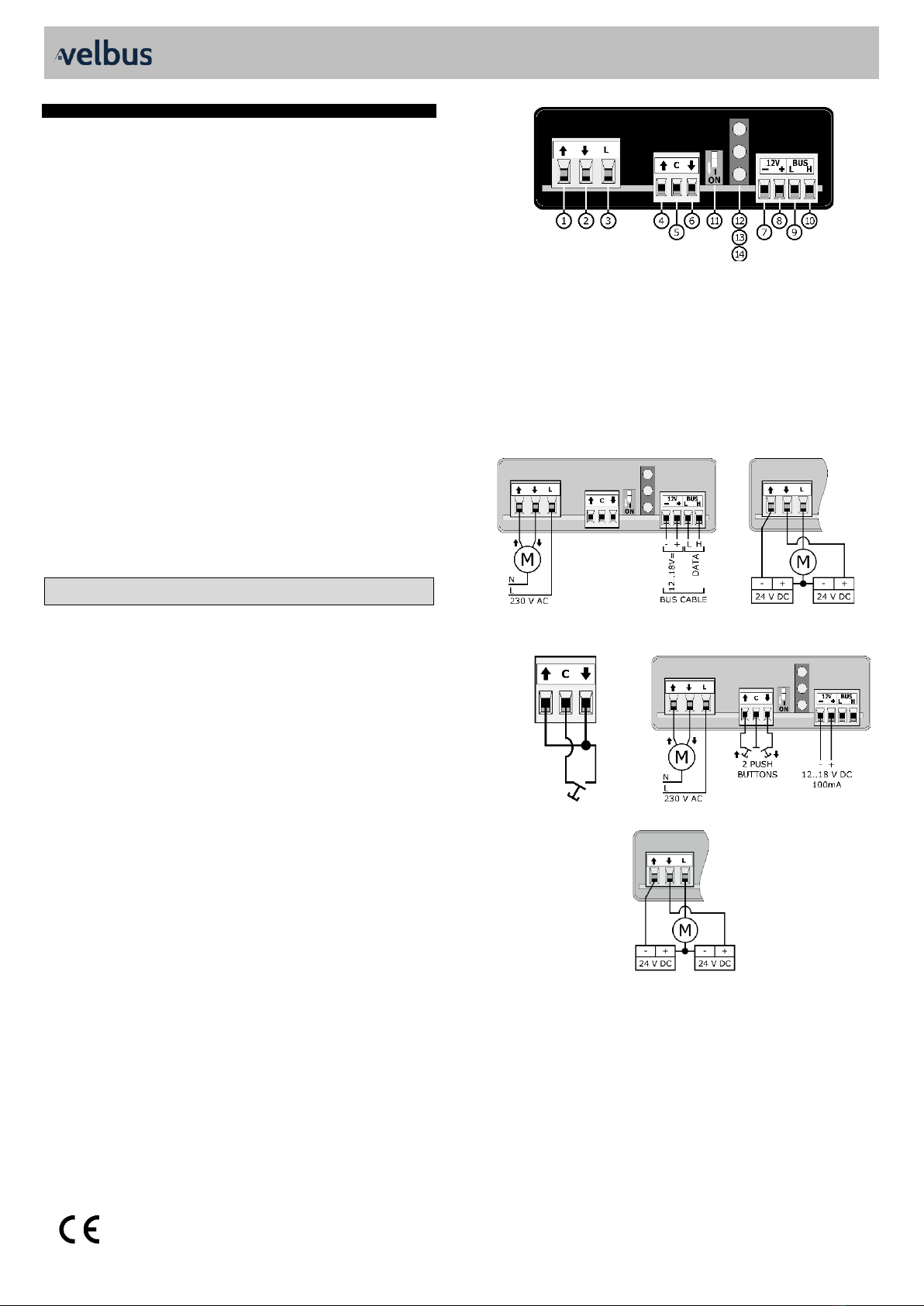
Allgemeine Informationen zur Installation und Konfiguration von Velbus, finden
Sie in der Anleitung und in den anderen Dokumentation auf www.velbus.eu.
LED-ANZEIGEN
•LED PS (Stromversorgung) ⑫:
oleuchtet kontinuierlich: Stromversorgung OK
oAus: Stromversorgung nicht OK
•LED aufwärts ⑬: blinkt, wenn der Rollladen aufwärts geht
•LED abwärts ⑭: blinkt, wenn der Rollladen abwärts geht
•Im Fehlerfall, blinken die LED aufwärts ⑬ und abwärts ⑭ gleichzeitig wie folgt:
o2 x Blinken, Pause, 2 x Blinken usw. Kommunikationsfehler (nur, wenn mit dem
Velbus-Datenbus verbunden und Adresse ≠ FF)
o3 x Blinken, Pause, 3 x Blinken usw. Stromversorgung zu niedrig
o4 x Blinken, Pause, 4 x Blinken usw. Stromversorgung zu hoch
BEMERKUNGEN
1. ADRESSIERUNG IN EINER VELBUS-INSTALLATION
Adressieren Sie VMB1BLS im Voraus. Verbinden Sie VMB1BLS mit einer Velbus-(test)-
Installation und verwenden Sie die Funktion “Address management” mit
automatischer Detektion in Velbuslink* (alle Anweisungen finden Sie in der
ausführlichen Anleitung vom VMB1BLS auf www.velbus.eu > Downloads). Velbuslink
detektiert VMB1BLS automatisch, wenn Sie den Druckknopf “Aufwärts” oder
“Abwärts” drücken (verbinden Sie ④ oder ⑥ mit ⑤).
Haben Sie VMB1BLS nicht im Voraus adressiert, gehen Sie wie folgt vor:
•In Velbuslink, rechtsklicken Sie auf den Rollladen-Kanal vom VMB1BLS, den Sie
adressieren möchten und wählen Sie “Operate” aus.
•Überprüfen Sie, welche der installierten Rollladen aufwärts oder abwärts gehen.
•Nun sehen Sie, welches VMB1BLS-Modul in Velbuslink mit dem Rollladen
übereinstimmt.
2. STANDALONE-BETRIEB
VMB1BLS kann auch als Standalone-Rollladencontroller (ohne Velbus-Installation)
verwendet werden. Ist dies der Fall, dann muss nur 12..18 V DC/100 mA (Anschlüsse
⑦ und ⑧) mit Strom versorgt werden und müssen BUS H ⑨ oder BUS L ⑩nicht
angeschlossen werden. Der Rollladen kann direkt über den mit dem “Druckknopf
aufwärts” ④, Druckknopf allgemein” ⑤ und “Druckknopf abwärts” ⑥verbundenen
Druckknopf (Druckknöpfe) angesteuert werden.
3. TERMINIERUNG
Jedes Velbus-Modul hat einen Terminierung für Abschlusswiderstand oder eine
Steckbrücke ⑪. In einer typischen Velbus-Installation stehen alle Terminierungen,
außer 2, offen. Diese zwei geschlossenen Terminierungen werden so weit wie
möglich voneinander installiert.
In einer Standalone-Installation vom VMB1BLS, spielt der Zustand Terminierung
keine Rolle.
*Version 9.28 oder höher
Dieses Produkt entspricht allen geltenden Europäischen Richtlinien
und Vorschriften.
SCHALTPLÄNE
Anschlüsse
Motor aufwärts
⑥
Druckknopf allgemein
Motor abwärts
⑦
Bus Stromversorgung -
Netz
⑧
Bus Stromversorgung +
(12..18 V DC)
④
Druckknopf aufwärts
⑨
Busdaten L
⑤
Druckknopf abwärts
⑩
Busdaten H
Andere Elemente
⑪
Terminierung
⑬
LED aufwärts
⑫
LED PS (Stromversorgung)
⑭
LED abwärts
1. VELBUS
WECHSELSTROMMOTOR 230 V
GLEICHSTROMMOTOR 24 V
2. STANDALONE
1 DRUCKKNOPF
WECHSELSTROMMOTOR 230 V
GLEICHSTROMMOTOR 24 V
Other manuals for VMB1BLS
1
Table of contents
Languages:
Other Velbus Control Unit manuals