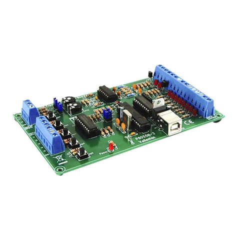
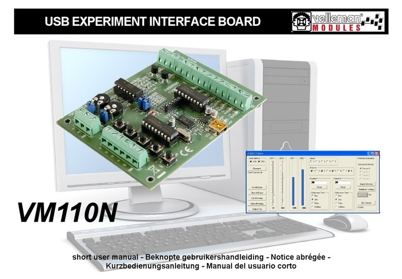
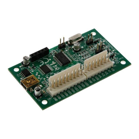
Velleman VM110 User manual

VM110
USB EXPERIMENT INTERFACE BOARD
Belgium [Head office] +32(0)9 384 36 11
France +33(0)3 20 15 86 15
Netherlands +31(0)76 514 7563
USA +1(817)284-7785
Spain +32(0)9 384 36 11

2
ND Vertaling van deze handleiding, alsook meer gegevens van deze module kan men terugvinden op de CD.
FR Vous trouverez la traduction de cette notice sur le CD, avec d'autres informations/données.
S Svensk Bruksanvisning och annan information finns på medföl jande CD.
SF Tämän käyttöohjeen sekä muun informaation suomenkielinen käännös on oheisella CD:llä.
ILa traduzione di questo manuale e tutte le informazioni concernenti l'unità possono essere trovate sul CD.
DK Oversættelsen af denne manual, samt alle øvrige informationer vedrørende enhederne, kan findes på
CD'en.
DDie Übersetzung dieser Bedienungsanleitung und alle anderen Informationen über diese Geräte finden Sie
auf der CD
SP La traducción de este manual de instrucciones y toda otra información sobre los dispositivos se encuen-
tran en el CD
PA tradução deste Manual e toda a informação referente às uni dades pode ser encontrada no CD.

3
Thank you for purchasing this module. Please read the instructions carefully to ensure correct and safe use.
WARRANTY
This product is guaranteed against defects in components and construction from the moment it is purchased and for a period of ONE YEAR starting from the
date of sale. This guarantee is only valid if the unit is submitted together with the original purchase invoice. VELLEMAN Ltd limits its responsibility to the
reparation of defects or, as VELLEMAN Ltd deems necessary, to the replacement or reparation of defective components. Costs and risks connected to the
transport, removal or placement of the product, or any other costs directly or indirectly connected to the repair, will not be reimbursed by VELLEMAN Ltd.
VELLEMAN Ltd will not be held responsible for any damages caused by the malfunctioning of a unit.
CONTENTS :
SPECIFICATIONS & FEATURES ....................................................................................................................................................................4
DEMO SOFTWARE............................................................................................................................................................................................5
CONTROL & INDICATORS...............................................................................................................................................................................6
CONNECTION DIAGRAM.................................................................................................................................................................................8
TEST PROCEDURE.........................................................................................................................................................................................10
This device complies with Part 15 of the FCC Rules provided the enclosed
instructions are followed to the letter. Use of the device is subject to the
following conditions: (1) this device must not cause harmful interference
and (2) the operation of this device should not be influenced by unwanted
interference.
More information about FCC can be look at http://www.fcc.gov
Contents

4
Specifications & features
Specifications and features
SPECIFICATIONS*
5 Digital inputs (0= ground, 1= open). On board test buttons provided.
2 Analog inputs (0 …+5V) with attenuation and amplification option. Internal test +5V provided.
8 Digital open collector output switches (max 50V/100mA). On board LED indication.
2 Analog outputs
0 to 5V, output resistance 1K5.
PWM 0 to 100% open collector outputs
max 100mA / 40V. On board LED indication.
General conversion time: 20mS per command
Power supply through USB approx. 70mA.
Diagnostic software and communication DLL included
*Modifications and typographical errors reserved.
DIAGNOSTIC / TEST SOFTWARE
Features:
Separate output / input test
Clear all / set all function
Counter function on inputs 1 and 2 with adjustable debounce (max 2KHz depending on the total I/O load).
Analogue output with sliders
Analogue input with bar graph indication

5
• Insert the included CD in your CD-ROM player.
Use the following procedure if the CD does not start up automatically :
1. Run setup.exe from the directory 'K8055_VM110 USB board/Demo PC soft install'
If the CD starts up automatically :
1. Choose "Browse this CD for other velleman software'
2. Run setup.exe from the directory 'K8055_VM110 USB
board/Demo PC soft install'
• An installation wizard will guide you trough the installation
procedure.
• By default the software is installed in the folder :
'C:\Program Files\Velleman\K8055'.
If the necessary software is not included or if you want to
check for updates, you can always download it for free from
our Velleman Website www.velleman.be
Demo software
Demo software

6
Control & indicators
5 digital inputs (e.g. push button, switch, relay contact, ...). Input is generally "high" (1), connection to GND makes the input
"low" (0).
Analogue inputs (e.g. temperature sensor, potentiometer, ...) 0 ... +5VDC MAX!
If the jumper is mounted, then you can use the internal voltage and adjust it using RV2/RV1. If the jumper is not mounted you
must use the external voltage A2/A1.
Adjusting of the internal voltage for input A1.
Adjusting of the internal voltage for input A2.
Address selection, open = 1, closed = 0
Analogue outputs :
• 2 analogue outputs with an output voltage between 0 and +5V (impedance 1K5).
• 2 PWM outputs with a pulse width modulation between 0 and 100%.
Digital outputs :
• 8 open collector contacts, to be connected with suitable inputs.
USB connection to computer using USB cable. correct address in the test program
1.
2.
3/4
5.
6.
7.
8.
9.
10.
Control & indications
REMARK: the analogue outputs and PWM outputs are always activated /deactivated together.

7
2
43
1
75 6
8
9
10
Control & indicators

8
Connection diagram
Connection Diagram
C
VELLEMAN 2003
P8055-1
From PC USB1.X
USB
OR
"1" "0" - +
ANALOG VOLTAGE 0 ...5V RVx : FOR EXPERIMENTAL USE
mount SK2 & SK3 when using RV1,2
To external electronics
analog output 0 ... 5V
-
+
-
+
RELAY
LED
220V
AC
EXTERNAL !
DC voltage 5 ... 30V
DC Adapter (ex. PS1208)

9
Warnings
WARNING
UK : PLEASE NOTE THAT THE GROUND OF THE BOARD IS NOT ISOLATED FROM
THE COMPUTER GROUND!
ND : DE MASSA VAN HET BORD IS NIET GESCHEIDEN MET DE COMPUTERMASSA!
FR : REMARQUEZ QUE LA TERRE DE LA PLAQUE N'EST PAS ISOLEE DE LA TERRE
DE L'ORDINATEUR !
D : BITTE VERGEWISSEM SIE SICH, DASS SICH DIE ERDUNG DER PLATINE UND
DIE ERDUNG DES COMPUTERS NICHT GEGENSEITIG ISOLIERT SIND!
ES : ¡OBSERVE QUE LA TIERRA DE LA PLACA NO ESTÁ AISLADO DE LA TIERRA
DEL ORDENADOR!
!

10
The included demo software makes it easy to experiment.
Start by selecting the address : tick off SK5 and/or SK6 (see address selection).
ATTENTION : Execute these settings before connecting the kit with the computer or before booting the computer.
Connect the USB cable.
LED LD3 'Power' lights up if the connection has been executed
properly.
After start-up LD8 (output 8) will flash momentarily to indicate that
the circuit works as it should.
Start the program 'K8055_Demo.exe'.
Next press the 'connect' button to connect the K8055 with the com-
puter.
The message "Card x connected" * is displayed if the connection is
successful, see fig.
* X is the number of the card.
SK5 SK6 ADDRESS
ON ON 0
OFF ON 1
ON OFF 2
OFF OFF 3
Test procedure
Test procedure

11
You can now simulate the inputs via push buttons Inp1 through Inp5. The matching check box remains ticked off as long as you
keep one of the push buttons pressed down.
Always tick off the check box for the matching output if you wish to test a digital output.
You can also conduct this procedure automatically : press the 'output test' button or activate all outputs with the 'Set all digital'
button. Press the 'output test' button to test all digital outputs automatically.
Test the analogue outputs with the 'set all analog' button and modify the output voltage with DA1 & DA2
Counter 1 & 2 are hardware integrated 16-bit counters, they are triggered by INP1 & INP2.
You can test the counter with push buttons Inp1 and Inp2 : the counter adds 1every time one of these two buttons is pressed. The
debouncing control allows you to determine the reaction time of the counter (0ms - 2ms - 10ms - 1000ms).
You can use the internal analogue voltage to simulate the analogue input via potentiometers ATT1 (RV1) & ATT2 (RV2).
The scroll bars AD1 & AD2 change on the screen whenever you adjust the position of the potentiometers. The "digital" value (0 to
255) of this internal analogue voltage can be read directly under the scroll bars.
When the input voltage is too low you can amplify it x4 / x15.
The analogue inputs A1 and A2 have a standard range of 0 ~ +5Vdc. To use them externally, remove the jumper caps on SK2 and SK3.
The internal 5V voltage source can only be used for testing purposes.
A gain of x4 requires a resistance of 3K3 for R8 (input signal 1) and for R9 (input signal 2). A x15 gain requires a resistance of 820ohm.
When the gain is set to e.g. x4, the max. input voltage falls inversely proportional to 1,25V.
If you want a different gain factor you can calculate it quite easily using the following formula :
Gain A1 = 1 + (R10/R8) Gain A2 = 1 + (R11/R9)
PLEASE BROWSE THE CD FOR MORE INFO AND SAMPLE SOFTWARE.
VISIT OUR WEBSITE REGULARY!
Test procedure

Modifications and typographical errors reserved - © Velleman nv. HVM110G - 2004 - ED1 (Rev 3.0)
USB EXPERIMENT INTERFACE BOAR
USB EXPERIMENT INTERFACE BOARD
D
D
5 410329 305819
Table of contents
Other Velleman Computer Hardware manuals
Velleman
Velleman PIC VM134 User manual

Velleman
Velleman VM205 User manual

Velleman
Velleman Whadda WPSH455 User manual

Velleman
Velleman VMA209 User manual

Velleman
Velleman RFM69HCW User manual
Velleman
Velleman VM167 User manual

Velleman
Velleman K8042 User manual

Velleman
Velleman K8055N User manual

Velleman
Velleman VMP403 User manual

Velleman
Velleman VMA452 User manual
Popular Computer Hardware manuals by other brands

ICP DAS USA
ICP DAS USA PISO-725 Series quick start guide

ICS ELECTRONICS
ICS ELECTRONICS 4865B user guide

Steltronic
Steltronic Stand Alone Vision Lane Computer installation manual

D-Link
D-Link DFE-690TXD user manual

Avalue Technology
Avalue Technology VMS-BYT Quick reference guide

AMX
AMX RDC-DC/277 Schematic diagram