Velleman HAA2890 User manual

DUAL RELAY DIGITAL ACCESS
CONTROL READER KEYPAD
W E AT H E R P R O O F
HAA2890
Programming & Installation Manual
FOR ELECTRIC LOCK
AND SECURITY SYSTEM INSTALLATIONS
HAA2890_Manual.indd 3 24/05/2012 15:21:11

2
TABLE OF CONTENTS
INTRODUCTION
FEATURES
SPECIFICATIONS
INSTALLATION
Precautions
Package Contents
CONNECTION HARNESS
The On-Board LED Indicators
The Pacifier Tones & The LED Signals
FEATURE PROGRAMMING & OPERATION INSTRUCTIONS
Set System in Programming Mode with The Master Code
Direct Access to Programming Mode with The “DAP” Code – 8 0 8 0
Refresh The System with The “Refreshing Code” --- 9 9 9 9
The Default Values of The Keypad
KEYPAD PROGRAMMING MAKE SIMPLE – For General Users
FEATURE PROGRAMMING -- KEY IN AND STORE THE DESIRED VALUES
Programming Criteria for Codes
Record A Master Code
Record A Super User PIN
Operation And Functions of The Super User PIN
Record The Common User PINs for Output 1
Record-Delete PINs or Cards for Output 1
Examples – Programming And Operation
Visitor Codes (For Output 1 Only)
Configuration of The Output Modes for Output 1
Personal Safety And System Lock-Out
User PIN Entry Mode
Pacifier Tones On-Off Selection
Output Operation Announcer
Status LED Flashing On-Off during Standby
Intelligent Egress Button – An Unique Feature of A Contemporary Keypad
Where And Why “Going Out” Needs Attention
Egress Delay and Warning
Configurations of The Egress Warning And Alarm
Close The Programming Mode
The Operation Modes
Wiegand Output at Keypad Operation Mode
THE APO DATA I/O PORT -- FOR SETTING UP A SPLIT-DECODED KEYPAD
The Optional DA-2800 Controller --- Introduction
PROGRAMMING SUMMARY CHART
APPLICATION EXAMPLE
Basic Wirings of A Stand Alone Door Lock
APPLICATION HINTS FOR THE AUXILIARY TERMINALS
........................................................................................4
.............................................................................................4
........................................................................................5
..........................................................................................6
..........................................................................................6
.........................................................................................6
................................................................................7
............................................................................8
.....................................................................8
.......................................................9
......................................................9
............................................9
..................................................10
.......................................................................10
.................................................11
........................................13
.........................................................................13
.................................................................................14
...............................................................................14
..........................................................15
..............................................................15
.................................................................16
...............................................................17
........................................................................19
.............................................................20
....................................................................20
..................................................................................21
..........................................................................21
............................................................................22
.................................................................22
.......................................23
...........................................................23
...............................................................................24
........................................................24
...........................................................................25
...................................................................................26
..............................................................26
........................................27
............................................................27
........................................................................28
..................................................................................30
.................................................................30
.......................................................31
HAA2890_Manual.indd 4 24/05/2012 15:21:12

3
VOOR VERPAKKINGEN
At the end of its life cycle, dispose of this product in accordance with local and national disposal
regulations. Read the manual thoroughly before bringing this device into service
Ontdoe u, ophet einde van zijn levensduur, van dit product volgens de plaatselijke en nationale
regelgeving inzake verwijdering. Lees deze handleiding grondig voor u het toestel in gebruik neemt.
A la fin de sa durée de vie, débarrassez-vous de ce produit en respectant la législation d'élimination
locale et nationale. Lisez le présent manuel attentivement avant la mise en service de l'appareil.
Tire las muestras inservibles en los correspondientes depósitos de eliminación de residuos según las
leyes locales y nacionales.Lea atentamente las instrucciones del manual antes de utilizar el aparato.
Entsorgen Sie dieses Produkt gemäß der örtlichen und nationalen Gesetzgebung bezüglich Entsorgung.
Lesen Sie diese Bedienungsanleitung vor Inbetriebnahme sorgfältig durch.
IN DE HANDLEIDINGEN
To all residents of the European Union
Important environmental information about this product
This symbol on the device or the package indicates that disposal of the device after its lifecycle could harm the environment.
Do not dispose of the unit (or batteries) as unsorted municipal waste; it should be taken to a specialised company for recycling.
This device should be returned to your distributor or to a local recycling service.
Respect the local environmental rules.
If in doubt, contact your local waste disposal authorities.
Aan alle ingezetenen van de Europese Unie
Belangrijke milieu-informatie betreffende dit product
Dit symbool op het toestel of de verpakking geeft aan dat, als het na zijn levenscyclus wordt weggeworpen, dit toestel schade kan
toebrengen aan het milieu.
Gooi dit toestel (en eventuele batterijen) niet bij het gewone huishoudelijke afval; het moet bij een gespecialiseerd bedrijf
terechtkomen voor recyclage.
U moet dit toestel naar uw verdeler of naar een lokaal recyclagepunt brengen.
Respecteer de plaatselijke milieuwetgeving.
Heeft u vragen, contacteer dan de plaatselijke autoriteiten inzake verwijdering.
Pour tous les résidents de l’Union européenne
Informations importantes sur la protection de l’environnement
Ce symbole figurant sur l’appareil ou sur l’emballage indique que l’élimination de l’appareil en fin de vie peut polluer
l’environnement.
Ne pas éliminer l’appareil (ou des batteries) avec des déchets non triés ; il doit être recyclé par une déchèterie.
Vous devez retourner l’appareil en fin de vie à votre distributeur ou à un service de recyclage local.
Il convient de respecter la réglementation locale relative à la protection de l’environnement.
En cas de doute, contactez les autorités locales.
HAA2890_Manual.indd 7 24/05/2012 15:21:12

INTRODUCTION
The HAA2890 is a weatherproof, self-contained, mullion mount compact keypad. It combines the functions of digital
keypad and proximity EM card reader in one unit.
The HAA2890 has been designed to work independently as a stand alone keypad or works together with an optional “APO
controller” to form a high security split-decoded keypad system.
The keypad comes with plenty of functions for owner’s selection via programming. Owners can take them freely to
tailor the desired features for their system.
HAA2890 is an ideal keypad mainly for Door Strike or Alarm Arm-disarm control. It is also a programmable industrial
timer (with the timing of 1 second to over 24 hours) for Automatic Operator systems.
The unit is designed for surface mounting on wall or door frame. The two relay outputs are coming with N.C. and N.O.
Contacts for Door strike and N.O. Contact for Door Bell.
FEATURES
A Member of The Tri-Tech Series Keypads Compatible with The APO Access Controller, DA-2800 or DA-2801
Durable Epoxy Coated Back-lit Key Board with Door Bell Button
Mullion Surface Mount Plastic Housing
Operated with PINs & EM Cards
Self-contained, Stand-Alone Operation
Built-in Data I/O Port Expandable for Split-decoded Operation
Relay Output Contacts for Door Strike and Door Bell
THE OPTIONAL CONTROLLERS FOR SPLIT-DECODED OPERATION
DA-2800 -- Full Feature Decoder + RF Remote Control
DA-2801 -- Full Feature Decoder
4
HAA2890_Manual.indd 8 24/05/2012 15:21:12

SPECIFICATIONS
Operating Voltage:
12V DC Nominal; 11-15V DC
Operating Current:
60mA (quiescent) to 95mA (two relays active)
Operation Temperature:
-20 C to +70 C
Environmental Humidity:
5-95% relative humidity non-condensing
Working Environment & Ingress Protection:
Indoor or Outdoor, IP-55 Weatherproof
Number of Users:
1,000 (PINs and/or Cards)
Proximity Card:
Standard EM Card or Keyfob, 125Khz
Number of Visitor Codes:
50, programmable for one time or with the time limit
Timings for Code Entry and Card Reading:
10 seconds waiting for next digit entry
30 seconds waiting for code entry after card reading
The Timer:
1-99,999 Seconds (Over 24 Hours possible) Programmable Timer for O/P 1
Egress Button:
Programmable for Instant, Delay with Warning and/or Alarm
Momentary or Holding Contact for the Exit Delay
Output Contact Ratings:
Output Relay 1 – N.C. & N.O. dry contacts, 2A/24VDC Max.
Door Bell Relay – N.O. dry contact, 1A/24VDC Max.
Tamper Switch – N.C. dry contact, 50mA/24VDC Max. , Magnet Operated Reed Switch
Dimensions:
168.5(H) X 46.5(W) X 24(D)mm
Weight:
160g net
Housing:
ABS Plastic Box
Specifications are subject to change for modification without notice
5
HAA2890_Manual.indd 11 24/05/2012 15:21:12

HAA2890_Manual.indd 12 24/05/2012 15:21:13

CONNECTION HARNESS
1 - 2 : TAMPER N.C. (Tamper Switch Normally Closed Contact)
A normally closed dry contact while the front cover is secured on the main box. It is open while the cover is
separated from the box. Connect this N.C. terminal to the 24 hour protection zone of an alarm system if necessary.
3 - 4 : DOOR BELL (Output Relay Contact for Door Bell)
It is a Normally Open (N.O.) relay dry contact with maximum rating of 24VDC/1Amp. It is prepared as a triggering
contact of a low voltage door chime. The contact point keeps close as long as the bell button on the keypad is
pressed.
5 - 6 : 12V DC (Power Input Terminal)
Connect to 12V DC power supply. The (
-
) supply and the (
-
) GND are the common grounding points of the system.
7 : EG IN ( Egress Input)
A Normally Open (N.O.) input terminal referring to (
-
) ground. With the help of connecting a normally opened button
to activate Output 1 for door opening in the same manner of using the Group 1 User PINs or Cards.
Egress button is usually put inside the house near the door. More than one egress buttons can be connected in
parallel to this terminal. Leave this terminal open if not used.
See Programming Location 90 for more information about the Egress Button with other features.
8 : GND (
-
) (Common Ground)
A common grounding point of the keypad
9 : DATA I/O (Data Input/Output Port for Split-Decoded Operation)
A data bus for signal communication with the optional Access Controller in Split-decoded operation.
See "THE APO I/O PORT" Section for the details.
7
THE WIRE HARNESS
HAA2890_Manual.indd 15 24/05/2012 15:21:13

10 - 11 - 12 : OUTPUT 1 (Output Relay 1)
2 Amp relay dry contact controlled by the Group 1 user PINs or Cards for Output 1, recommended for door strike.
Terminal 10 is Normally Closed (N.C.), terminal 12 is Normally Open (N.O.) and terminal 11 is the common point of
the two contacts. Use N.C. output for Fail-safe locking device; and N.O. output for Fail-secure locking device. The
relay is programmable for Start/Stop (toggle) mode or Momentary timing mode. See programming Location 51 for
the details.
THE ON-BOARD LED INDICATORS
MAINS (AMBER)
------
It flashes on Standby. It shows the system status in synchronization with the beep tones.
The standby flashing can be set to OFF in programming. See Location 73 for the details.
DOOR (GREEN) ----
---
- It lights up for Output 1 activation.
INHIBIT (RED) ---------- It lights up while the output is inhibited.
THE PACIFIER TONES & THE LED SIGNALS
The buzzer and the amber LED indicator give following tones and signals respectively for system status:
STATUS TONES * LED SIGNALS
1) On Programming Mode ----- ON
2) Successful Key Entry 1 Beep 1 Flash
3) Successful Code / Card Entry 2 Beeps 2 Flashes
4) Unsuccessful Code / Card Entry 5 Beeps 5 Flashes
5) Power Up Delay Continuous Beeps Continuous Flashes
6) Output Relay Activation ** 1 Second Long Beep
7) On Standby *** ----- 1 Flash in 1 Second Interval
8) System Refreshing ----- Fast Flashes for 2.5 Minutes
9) Card or PIN Already Stored in System 1 Long Beep -----
NOTE:
* All Pacifier Tones can be ON or OFF through the programming option at Location 71
* * The Output Relay Activation beep can be selected through the programming option at Location 72
* * * The Standby flashing can be ON or OFF through the programming option at Location 73
8
HAA2890_Manual.indd 16 24/05/2012 15:21:13

9
FEATURE PROGRAMMING & OPERATION INSTRUCTIONS
SET SYSTEM INTO PROGRAMMING MODE WITH THE MASTER CODE
IMPORTANT NOTE:
1) DO NOT TURN OFF POWER while the keypad is in Programming Mode. Otherwise, it may cause data lost/error to the
programmed features in the memory.
2) The keypad beeps after power up. Wait 1 minute until the end of the power up delay, then key in the Master Code for
setting the system into programming mode.
3) For the owner’s convenience in programming at the first time, the factory has put a Master Code 0 0 0 0 into the
keypad (It is NOT a default code). To compromise security, in all cases, the owner should program a new Personal
Master Code to invalidate the factory set Master Code after the keypad is owned.
MASTER CODE
The Master Code can be a factory set master code or the private master code that
was set by the owner.
Validate the master code with * * .
2-beep confirms a valid master code. The Mains LED (Amber) is constantly ON after the system is set in the
programming mode.
DIRECT ACCESS TO PROGRAMMING MODE WITH THE “DAP” CODE – 8 0 8 0
Set System Into Programming Mode With DAP Code In Case Of The Master Code Is Forgotten ! !
The owner requires to apply the following procedures precisely to set the system into programming mode
with the DAP code 8 0 8 0.
1) Switch OFF all the power for 1 minute to ensure that the system is fully discharged.
2) Swich ON power again. The system is in Power-up Mode for 1 minute and the buzzer gives beeps during the whole
period. This is the only time limit for setting the system to Direct Access to Programming (DAP).
3) Press the Egress Button (EG IN) once first to enable the DAP function.
4) Key in the DAP Code 8 0 8 0 and validate it with * * , the existing Master Code in the memory is erased and the
power up beep stops. The keypad turns itself into programming mode like using the Master Code and it is ready to
accept the new programming data.
5) If the Egress Button is not pressed and the DAP code is not keyed in within the power up period, the system will set
itself to normal operation mode. To set it back to power-up mode, repeat procedures 1-4.
DAP CODE
The DAP code is fixed on 8 0 8 0 and it is valid only in the Power-up Period after the Egress Button is pressed.
Validate the DAP code with the * * .
2-beep confirms the system is in the Programming Mode; and the Mains LED is constantly ON.
See “RECORD A MASTER CODE” at “Location 01” for the details of programming a new master code.
NOTE:
If the keypad is linking up with the DA-2800 or DA-2801 controller in the Split-decoded operation, it is necessary to put
the controller’s “Link-up Jumper” to “ON” position to get the new Master Code for it. As the Master Code is also the
link-up code of the two units. Do Not Forget to put the Link-up jumper back to OFF position after the programming.
0000
8080
**
**
MASTER CODE VALIDATION
DAP CODE VALIDATION
EGRESS BUTTON
PRESS ONCE
HAA2890_Manual.indd 19 24/05/2012 15:21:13
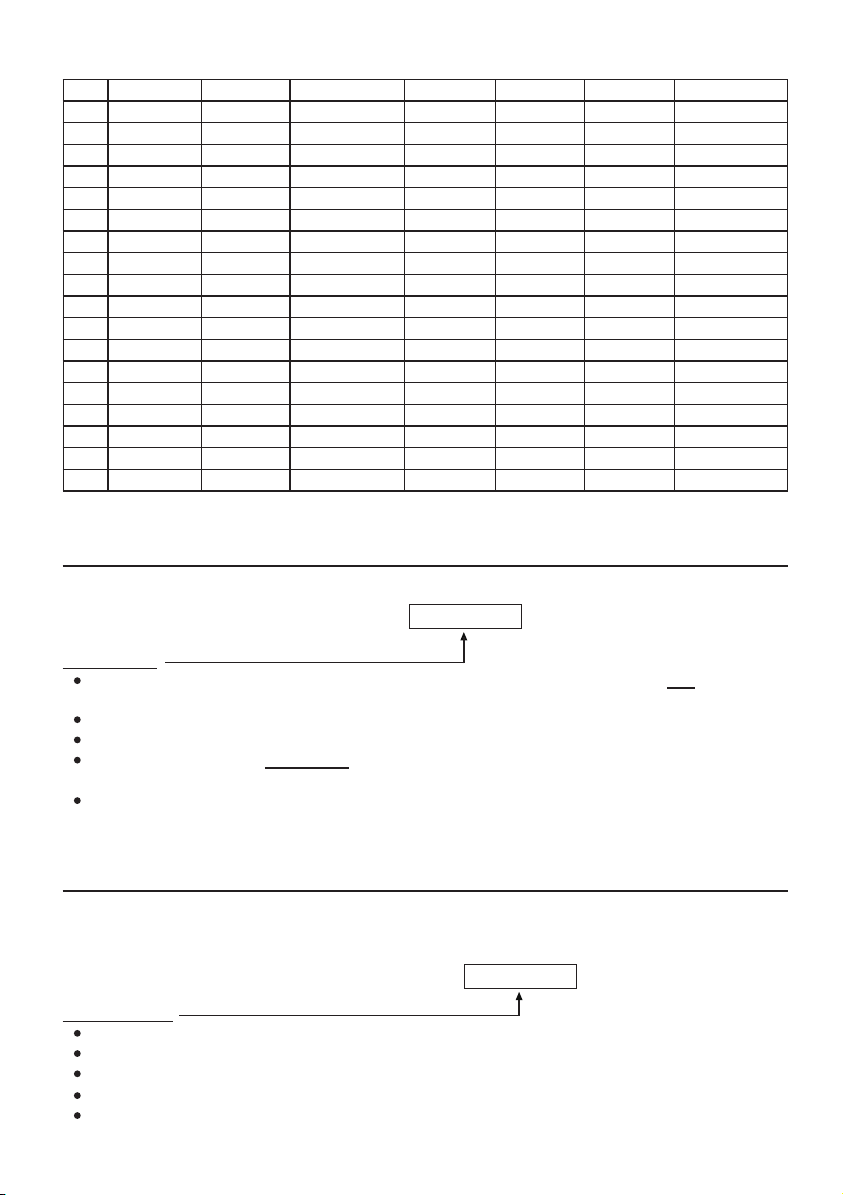
REFRESH THE SYSTEM WITH THE “REFRESHING CODE” --- 9 9 9 9
The system can be refreshed to clear all the old data stored and back to its ex-factory default values.
IMPORTANT NOTE:
Make sure that you really want to clear ALL the OLD data before entering of the Refreshing Code. The keypad will be
back with its default values like a new unit. Re-program of the desired values are necessary.
REFRESHING CODE
The Code 9 9 9 9 is for refreshing of the system. Once it is keyed in and validated with #, all the values
programmed previously will be cleared EXCEPT the Master Code.
The refreshing takes around 2.5 minutes. During the keypad is being refreshed the Status LED (Amber) flashes fast
until the end.
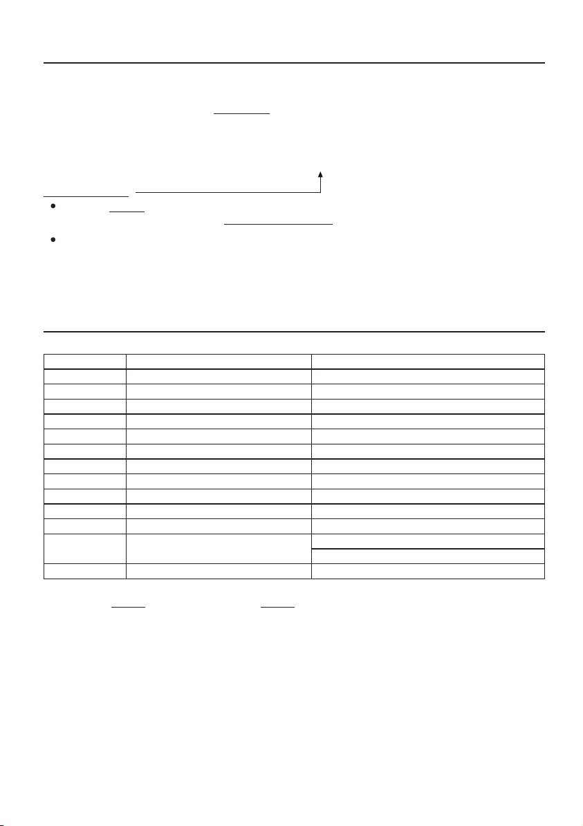
THE DEFAULT VALUES OF THE KEYPAD
PROGRAMMING
LOCATION PARAMETERS DEFAULT FUNCTIONS & VALUES
0 1 Master Code 0 0 0 0 Factory Set, Not a default value *
0 2 Super User PINs Nil ----- User Program Required
0 3 Common User PIN 1 Nil ----- User Program Required
1 0 User PINs & Cards for O/P 1 Nil ----- User Program Required
4 0 Visitor Codes Nil ----- User Program Required
5 1 O/P Mode of The O/P 1 Time = 5 Sec, Momentary
6 0 Personal Safety & Lock-out Code = 1, 10 False Code/Card Lock-out 60 Sec
7 0 User Code Entry Mode Code = 2, Manual Entry Mode
7 1 Pacifier Tones ON-OFF Selection Code = 1, Pacifier Tone ON
7 2 O/P Operation Announcer Code = 1 Sec, Notification Beep ON
7 3 Status LED Standby Flashing ON-OFF Code = 1, Flashing Enabled
9 0 Egress Delay & Warning Code 1 = 0, Instant, No Delay
Code 2 = 1, Momentary Contact without Warning
9 4 Operation Modes Code = 0, Stand Alone Keypad
NOTE:
The DAP Code 8 0 8 0 and the Refreshing Code 9 9 9 9 are fixed in the operating system program. It can not be
changed in any ways or be influenced by the system in default setting.
REFRESHING CODE VALIDATION
9999 #
10
HAA2890_Manual.indd 20 24/05/2012 15:21:13

KEYPAD PROGRAMMING MAKE SIMPLE – For General Users
The HAA2890 has many functions for user’s selection. For those general users taking the keypad for door strike only,
most of the features can be kept in their Default values. Only the User PINs / Cards and a private Master Code are
necessary to program for the system.
The keypad accepts 1) Card only, 2) PIN only, 3) Card + PIN or 4) Card + Common User Code to operate its outputs.
PROGRAMMING
NOTE: Wait 1 minute until the end of the power up delay.
1) Set System into Programming Mode with The Factory Set Master Code 0 0 0 0
---- 2 beeps, system is in Programming Mode
Note:If the Master Code is forgotten, use the DAP Code to set the system into programming mode. See DAP CODE
8080 on the previous page for the details.
2) Change The Factory Set Master Code to Owner’s Private Master Code for Security Reason
---- 2 beeps, 3 2 8 9 is a Master Code for example here only
3289 is the new Master Code and the 0000 is erased
3) Record an “EM Card” to Operate The Output 1 for Door Open
(a) (b) (c) (d) (e)
(a) 10 = Programming Location for Output 1
(b) 1 = Programming option for EM Card only
(c) 001 = One of the 1,000 User IDs for the User PIN/Card from 000-999
(d) Read Card = Put the Card close to the card reader
(e) # = Confirm the card is read, 2 beeps
4) Set an “User PIN” to Operate The Output 1 for Door Open
(a) (b) (c) (d) (e)
(a) 10 = Programming Location for Output 1
(b) 2 = Programming option for User PIN only
(c) 002 = One of the 1,000 User IDs for the User PIN/Card from 000-999
(d) 8321 = The User PIN that is programmed for door open. 8321 is an User PIN for example here only
(e) # = Confirm the User PIN, 2 beeps
5) Record an “EM Card + User PIN” to Operate The Output 1 for Door Open
10 3 003 6123 #
(a) (b) (c) (d) (e) (f)
(a) 10 = Programming Location for Output 1
(b) 3 = Programming option for EM Card + User PIN. (The User PIN can be repeated use or proprietary)
(c) 003 = One of the 1,000 User IDs for the User PIN/Card from 000-999
(d) Read Card = Put the Card close to the card reader
(e) 6123 = The User PIN to be used with the EM Card. 6123 is an User PIN for example here only.
(f) # = Confirm the Card+PIN is stored, 2 beeps
0000 **
01 3289 #
10 2 002 8321 #
10 1 001 #
READ CARD
READ CARD
11
HAA2890_Manual.indd 23 24/05/2012 15:21:14

6) Record an “EM Card + Commom User Code” to Operate The Output 1 for Door Open
10 4 004 #
(a) (b) (c) (d) (e)
(a) 10 = Programming Location for Output 1
(b) 4 = Programming option for EM Card + Common User Code
(c) 004 = One of the 1,000 User IDs for the User PIN/Card from 000-999
(d) Read Card = Put the Card close to the card reader
(e) # = Confirm the card is read, 2 beeps, the Common User Code goes to this User ID automatically
(f) A Common User Code (for example: 8 6 2 5) MUST be set at the Programming Location 03 first for this operation
mode. The code can be used for all the EM Cards in this operation mode.
REMARK:
If more User PINs and Cards are required for Output 1, repeat the procedures (3) , (4) , (5) or (6) above with other User
IDs, such as 005, 006, 007 --- 999 etc. Total 1,000 users are allowed. See Programming Location 10 for the details.
7) Close The Programming Mode
---- 2 beeps
The programming mode is closed. The keypad is back to normal operation mode
OPERATION
8) Open The Door with The EM CARD
---- 2 beeps, the door is open
9) Open The Door with The User PIN
8321 #---- 2 beeps, the door is open
10) Open The Door with The EM CARD + User PIN
6123 #---- 2 beeps, the door is open
11) Open The Door with The EM CARD + Common User Code
8625 #---- 2 beeps, the door is open
REMARK:
In the next Section, “KEY IN AND STORE THE DESIRED VALUES” describes all the features and functions of the system
in detail. Users can follow them to tailor the desired values for their access control systems. Suggest the general users
also spend some time on them to get acquaint with this powerful system for future expansion.
READ CARD
READ CARD
READ CARD
**
12
READ CARD
HAA2890_Manual.indd 24 24/05/2012 15:21:14

FEATURE PROGRAMMING -- KEY IN AND STORE THE DESIRED VALUES
The feature values can be set and stored into the system one by one with the desired Programming Locations.
Programming can be made continuously and it is not necessary to be in sequence order. Just go to the desired
programming location and key in the value for the desired feature.
IMPORTANT NOTE --- Programming Criteria for Codes:
a) The Prime Codes:
All the Private User PINs, Master Code, Duress Codes, Super User PIN, Common User Code and the Visitor User Codes
belong to Prime Codes in the system. They have the priority to be read and they MUST be unique and can not be
repeated in the programming. A Prime code also can NOT be duplicated for a Secondary code to work with the EM Card
or vice versa.
b) The Prime Cards:
All the EM Cards used in this system are Prime Cards. The cards MUST be unique and can not be repeated use. The
Card always has the priority to be read when working with an User PIN in “EM Card + Secondary PIN” or EM Card +
Common User PIN”.
c)Warning for A Repeated Use of Prime Code or Card:
One long beep is given if a Code/PIN is keyed in or a Card is read. It means that a Prime Code or a Prime Card is
repeated. The Code/PIN or Card was already in one of the PIN or Card Locations or IDs. The programming is invalid.
Change a new Code/PIN or Card and program it again.
d)Secondary User PINs:
The Secondary User PINs are prepared to enhance security. It is put after a Card in “EM Card + Secondary User PIN”
programming. They can be a repeated code within the Secondary PINs but it is NOT allowed a duplicate of the Prime
Codes. The system will reject a duplicated Prime Code for Secondary User PIN or vice versa.
e)Getting Advantages from The Secondary User PINs:
The repeated Secondary PINs can be used as a Group Common User Code or called Department User Code for a group
of EM Cards, which simplifies the programming of using large number of different User PINs. EM Card with Department
Code prevents a lost card used by people of other department. Also, it will be easier to trace out the department of the
lost card belongs to. Of cause, the owner can use a proprietary Secondary User PIN for each EM Card in the “EM Card
+ Secondary User PIN” programming to further increase the security if it is the main concern.
f) Security Level Comparison of The Secondary User PIN/Code following Card Reading:
i) EM Card + Common User Code --- All EM Cards use the same User Code. Security level is better than just Card
only. A lost Card picked up by any people can be used if he knows the Common User Code.
ii) EM Card + Department User Code --- The EM Cards are divided into groups with a Department User Code. A lost
Card can be used only by the people in the same group who know the Department Code.
iii) EM Card + Secondary User PIN --- Each EM Card has its own proprietary User PIN. A lost Card can not be used
by other people.
g) Make A List Recording of The User Names VS User Codes:
Suggest the owner to make a list recording of the User Names corresponding to the Codes/PINs/Cards that are going to
store in the Locations and the IDs before the programming. It will be a useful tool for the owner to easily program them
smoothly and also to trace them from this multi-users system in the future.
Example: (Please see the following page)
13
HAA2890_Manual.indd 27 24/05/2012 15:21:14
Example:
User Name Location Function Code User ID PIN/Code Card # Remark
1
2
3
4
5
6
7
8
9
10
11
12
13
14
15
16
--
1,000
RECORD A MASTER CODE (Location 01)
MASTER CODE
Master Code is the authorization code for setting the system to programming mode. It is NOT an User Code
operating of the output relays.
The Master Code can be 4 to 8 digits. Press # key to confirm code entry
When a new master code is keyed in and confirmed, the old master code is replaced automatically.
The master code is also the Link-up Code between the keypad and the optional controller of the system in Split-
decoded operation.
Example: Set a Master Code with the number of “2 2 3 3” ----
RECORD A SUPER USER PIN (Location 02)
The Super User PIN has TWO functions. It is prepared for the owner to use it to operate the keypad under inhibit
condition and make operation of inhibit enable / disable to the system output.
SUPER USER PIN
The Super User PIN can be 4 to 8 digits.
Two beeps will be heard after pressing the # key to confirm code entry.
When a new Super User PIN is keyed in and confirmed, the old one is replaced.
Example: Set a Super User PIN with the number of “2 5 8 0” ----
To deleted a Super User PIN from memory: Key in just the Location number and #. ----
4 to 8 Digits
SUPER USER PIN VALIDATIONLOCATION
02
02 2580 #
02 #
#
4 to 8 Digits
MASTER CODE VALIDATIONLOCATION
01
01 2233 #
#
14
HAA2890_Manual.indd 28 24/05/2012 15:21:14

OPERATION AND FUNCTIONS OF THE SUPER USER PIN
1) Operate Output 1 (Output Relay 1)
The operation of the Super User PIN is just like a normal User PIN. Simply key-in the PIN with a specific output
number for the Output. The Super User PIN can also be used to reset an operating output timer instantly.
---------- Output 1 Activates or Resets
2) Inhibit The User PINs For Output 1
The Super User PIN can also be used to inhibit the normal User PINs/Cards for the Output 1 (usually they are for
door strike). It enhances the security level of the access control system, such as to stop a keypad after office hour
or while the house is nobody inside. Once the Output 1 is inhibited, the User PINs/Cards for it become invalid and
those people even know the User PINs are refused during the system is inhibited. The inhibit function is toggled in
Start / Stop mode with the following code entry.
---------- The Whole Group of User PINs & Cards for Output 1 are Disabled
or Enabled in Toggle
NOTE:
The inhibit function setting with the Super User PIN applies to the whole group of User PINs and Cards for
Output 1.
For safety reason, the inhibit function initiated with the Super User PIN does not govern the Egress Button. The
door still can be opened with it from inside.
The function of the Super User PIN is not affected in the Inhibited Mode or Lock-out Mode. It is always a normal
user code for Output 1.
RECORD THE COMMON USER PINS FOR OUTPUT 1 (Location 03)
The Common User PIN is prepared for operating of the Output 1 as an enhance code. The Common User PINs MUST
work in the form of “Card + Common PIN” to operate the outputs to increase the security of the access control
system. See Location 10 for more information.
NOTE : Common User PIN alone can NOT be used to operate Output 1 directly.
COMMON USER PIN LOCATION
-- Location Stores The Common User PIN for Output 1
COMMON USER PINS
The Common User PIN can be 4 to 8 digits. Press # key to confirm the code entry.
When a new Common User PIN is keyed in and confirmed, the old one is replaced.
Example: Set a Common User PIN with the number of “1 3 5 7” for Output 1 ----
To deleted a Common User PIN from memory: Key in just the Location number and #. ----
4 to 8 Digits
SUPER USER PIN
SUPER USER PIN
COMMON USER PIN VALIDATIONLOCATION
# 1
# 9
03 1357 #
03 #
03
#
03
15
HAA2890_Manual.indd 31 24/05/2012 15:21:14

RECORD-DELETE PINS OR CARDS FOR OUTPUT 1 (Location 10)
Total of 1,000 User PINs and/or Cards are available for controlling of the output relay 1.
The Private User PINs and Cards MUST be unique. Repeated PINs will be rejected. Secondary User PINs in the “EM
Card + Secondary User PIN” can be repeated. See the Important Note --- Programming Criteria for Codes in page 13
for more information.
USER GROUP LOCATION
– Group 1 --For User PINs/Cards Controlling Output 1
1,000 Users are allowed in group 1 for O/P 1
SELECTION OF OPERATION MEDIA
Number 1, 2, 3 or 4 represents the Media to be used to operate the keypad.
Number 5 is the authorization code for deleting of an PIN and/or Card from
its User ID.
= EM Card only; = Private User PIN only;
= EM Card + Secondary User PIN = EM Card + Common User PIN
= Delete an User PIN &/or Card from the selected User ID number
= Clear all the PINs & Cards from the selected Location. It takes
few seconds to a minute to complete depending on the Location
selected and the data stored.Please see the programming example
below for the details.
USER ID NUMBER
A 3-digit ID is an identified number for each User PIN and/or Card.
Repeated ID number will be rejected by the system
ID Number 000
-
999 for 1,000 User PINs/Cards to operate Output 1
CARD &/OR USER PINS
The User PINs can be 4-8 digits. Key in the User PIN on each ID Number box, then confirm it with # key
Just simply put the EM card close to the reader window to read it on each ID Number box, then, confirm it with
# key if it is a Card ONLY, or Card + Common User PIN entry. The Common User PIN is NOT required to key-in
here. It will go into its location automatically after the Card is read.
Read the Card first, then key in the Secondary User PIN on each ID Number box, then confirm it with # key if it
is Card + Secondary User PIN. The Secondary User PINs can be duplicated or a proprietary User PIN but can
not be a duplicate of a Prime Code. Owner can use the same secondary User PIN for a group of Cards as a group
Common User Code (or called Department Code) for a specific relay output.
Cards (Operation Media # 1, 3, & 4) and Private User PINs (Operation Media 2) MUST be unique. A repeated EM
card or Private User PIN will be rejected and one long beep will be generated by the system to notify the owner.
10 1
-
5 000
-
999 #
10
1 2
3 4
5
0999
CARD &/OR USER PIN VALIDATIONLOCATION MEDIA USER ID
CARD &/OR USER PIN
16
HAA2890_Manual.indd 32 24/05/2012 15:21:14

EXAMPLES – PROGRAMMING AND OPERATION
1) Example 1 -- EM Card Only :
i) Programming :
10 1 001 #
(a) (b) (c) (d) (e)
(a) The card is programmed for operating of the Output 1
(b) The operation is EM Card only
(c) Take ID number 001 in Group 1 to store the card, which is one of the IDs in 000-999
(d) Put the card close to the reader to read it, one beep confirms the reading
(e) Press # to store the “Card” into memory, two-beep confirms a valid entry
ii) Operation : (while the system is back to operation mode)
(a)
a)Put the EM card close to the reader. Two-beep confirms the card is read and the Output 1 activates
2) Example 2 -- Private User PIN Only :
i) Programming :
10 2 002 1234 #
(a) (b) (c) (d) (e)
(a) The Private User PIN is programmed for operating of the Output 1
(b) The operation is Private User PIN only
(c) Take ID number 002 in Group 1 to store the Private User PIN, which is one of the IDs in 000-999
(d) Put Private User PIN “1 2 3 4” into the storage location
(e) Press # to confirm and store the “Private User PIN” into memory, two-beep confirms a valid entry
ii)Operation : (while the system is back to operation mode)
1234 #
(a) (b)
(a) Key in the Private User PIN “1 2 3 4”
(b) Confirm it with the # key. Output 1 activates
3) Example 3 -- EM Card + Secondary User PIN :
i) Programming :
10 3 003 24680 #
(a) (b) (c) (d) (e) (f)
(a) The card is programmed for operating of the Output 1
(b) The operation is EM Card + Secondary User PIN
(c) Take the ID number 003 in Group 1 to store the Card & PIN, which is one of the IDs in 000-999
(d) Put the card close to the reader. One beep confirms the reading
(e) Put Secondary User PIN “2 4 6 8 0” into the storage location
(f) Press # to store the “Card + Secondary User PIN” into memory, two-beep confirms a valid entry
ii) Operation : (while the system is back to operation mode)
24680 #
(a) (b) (c)
(a) Put the EM card close to the reader. Two-beep confirms the reading and 30 seconds waiting time is given for the
entry of the User PIN, the Amber LED keeps flashing
(b) Key in the Secondary User PIN “2 4 6 8 0”
(c) Confirm it with the # key. Output 1 activates
Read Card
Read Card
Read Card
Read Card
17
HAA2890_Manual.indd 33 24/05/2012 15:21:14

4) Example 4 -- EM Card + Common User PIN :
i) Programming :
10 4 004 #
(a) (b) (c) (d) (e)
(a) The card is programmed for operating of the Output 1
(b) The operation is “EM Card + Common User PIN”
(c) Take ID number 004 in Group 1 to store the card, which is one of the IDs in 000-999
(d) Put the card close to the reader. One beep confirms the reading. (No need to key in a Common User PIN but
there MUST be a Common User PIN already recorded in Location 03;
(e) Press # to store the “Card” into memory. Two-beep confirms a valid entry
ii) Operation : (while the system is back to operation mode)
#
(a) (b) (c)
a) Put the EM card close to the reader. One-beep confirms the reading and 30 seconds waiting time is given for the
entry of the Common User PIN, the Amber LED keeps flashing
b) Key in the Common User PIN “1 3 5 7” (the number programmed in “Location 0 3” for Output 1 in the previous
Example)
c) Confirm it with the # key. Output 1 activates
5) Example 5 -- Delete an User PIN & / or EM Card :
i) Delete An User PIN or A Lost EM Card
10 5 #
(a) (b) (c) (d)
a) Key in the User Group that the User ID belongs to. “10” for the Group 1. This keypad has user Group 1 only
b) Key in “5” that is the Command Code for making a deletion here
c) Key in the User ID that stored the User PIN, the lost EM card or the EM Card+User PIN
d) Press the # key. Two-beep confirms a valid entry and the PIN and/or Card in that User ID is cleared
ii) Delete an EM Card
10 5 #
(a) (b) (c) (d)
a) Key in the User Group that the EM Card belongs to. “1 0” for the Group 1. This keypad has user Group 1 only
b) Key in “5” that is the Command Code for making a deletion here
c) Put the EM card close to the reader. One-beep confirms the reading. Read the Card only also makes a valid
deletion to the Card working with the Common User PIN or the Secondary User PIN
d) Press the # key. Two-beep confirms a valid entry. The EM Card in that User ID is cleared. Key in the User ID is not required.
6) Example 6 – Clear The Whole Group of Users :
Whole group of users including the PINs and Cards can be cleared with the following command.
10 0999 #
(a) (b) (c)
a) The User Group 1 – “10” is selected to be cleared. This keypad has user Group 1 only
b) Key in the Group Deletion Command, 0 9 9 9
c) Confirm the deletion with #. All the User PINs and Cards in the Group 1 are cleared. It takes few seconds to
a minute to complete depending on the data stored.
Read Card
User ID
Read Card
Common User PIN
Read Card
18
HAA2890_Manual.indd 30 24/05/2012 15:21:14

VISITOR CODES (FOR OUTPUT 1 ONLY) (Location 40)
The Visitor Codes are the temporary user codes for operating of the Output 1 (mainly for door strike in access control).
They can be programmed as “One Time Codes” or “Codes with Time Limit”. The Visitor Codes will be cleared
automatically after use if they are one time codes, or, when the allowed time expires.
VISITOR ID
50 Visitor IDs for storing the codes. They are represented by a
Two-digit ID Number of 01 to 50.
0999 = Clear all the Visitor Codes from Location 40. Please
see the Programming example below for the details.
VALID PERIOD
The codes in this box MUST be two digits and they represent the time of the operation.
00 --- One Time Code
One Time Code has no time limit but it can only be used for ONCE.
It is cleared by the system automatically after use.
01
-
99 --- Time Limit in Hour(s)
The Visitor Code can be set with the valid time limit of 1 Hour to 99 Hours with a
two-digit number of 01 to 99. The visitor code is cleared by the system when
the time limit reaches.
VISITOR CODES
When a new Visitor Code is put in the same Code box, the old code is replaced.
The Visitor Codes can be 4-8 digits for the Manual Mode code entry.
The Visitor Codes MUST be in the same digit length with the Master Code for Auto Mode code entry.
NOTE: All Visitor Codes will be cleared after power down to prevent extension/confusion of their valid time limit.
EXAMPLES:
Example 1: Set a “One Time Visitor Code” with the number of “1 2 6 8” for the Output 1
40 01 00 1268 #
(a) (b) (c) (d) (e)
(a) Visitor Code Programming, (b) The Visitor ID, (c) An One Time Code, (d) The Visitor Code, (e) Entry Confirmation
Example 2: Set a “Visitor Code” with the number of “1 3 7 8” that is valid for three hours for the Output 1
40 02 03 1378 #
(a) (b) (c) (d) (e)
(a) Visitor Code Programming, (b) The Visitor ID, (c) Valid for 3 Hours, (d) The Visitor Code, (e) Entry Confirmation
Example 3: Delete a “Visitor Code” from Vistor ID 02 in the memory
40 02 #
(a) (b) (c)
(a) Visitor Code Programming, (b) The Visitor ID, (c) Delete Confirmation
Example 4: Clear all “Visitor Codes” from Location 40
40 0999 #
(a) (b) (c)
(a) Visitor Code Location, (b) The Deletion Command Code, (c) Confirmation, all Visitor Codes are cleared
4-8 DIGITS
40 #
01
-
50 00 or 01
-
99
VISITOR CODE VALIDATIONLOCATION VISITOR ID VALID PERIOD
19
HAA2890_Manual.indd 29 24/05/2012 15:21:14

CONFIGURATION OF THE OUTPUT MODES OF OUTPUT 1 (Location 51)
The relay output of this keypad is programmable for Start/Stop or Timing modes. Apart from the door access control,
alarm arm-disarm control, it is also an universal timer for automatic operator in industry with its 99,999 seconds (over
24 hours) programmable timer.
OUTPUT LOCATION
51 -- Location for Output 1
OUTPUT MODE & TIMING
0– Start /Stop Mode (Toggle)
The number 0 sets the output to the Start / Stop mode. The output Starts when an User PIN and/or Card is entered/
read; the output Stops when an User PIN and/or Card is entered/read again.
1
-
99999 Seconds Momentary --- (Default -- Momentary 5 Seconds)
The output can be set in Momentary Mode with the time of 1 second to 99,999 seconds. The output will reset
automatically when the time expires OR it can be RESET manually at anytime with the Super User Code before the
end of the time.
Example : Reset Output 1 -- # 1------------- Output 1 resets
PERSONAL SAFETY AND SYSTEM LOCK-OUT (Location 60)
SAFETY & LOCK-OUT OPTIONS
The Options are represented by their Mode Numbers in programming. They are described below:
1--- After 10 successive false Card/User Code trials, the keypad locks during 60 seconds. -- (Default)
5
-
10 --- Selection of after 5 to 10 successive Card/User Code trials, the keypad locks during 15 minutes.
The keypad can be reset to release the lock-out with the “Super User Code” in the following way.
Example : Release the lock-out -- # 9
00 --- Disappearance of all the above lock-out securities.
SUPER USER CODE
1 to 2 Digits
LOCK-OUT MODES VALIDATIONLOCATION
60 #
SUPER USER CODE
OUTPUT MODE & TIME VALIDATIONLOCATION
51 0 or 1
-
99999 #
20
HAA2890_Manual.indd 26 24/05/2012 15:21:14
Table of contents
Other Velleman Keypad manuals

Velleman
Velleman PCUSB29 User manual

Velleman
Velleman HAA9350 User manual

Velleman
Velleman CTC1000KP User manual

Velleman
Velleman etiampro HAA2866N User manual

Velleman
Velleman HAA263D User manual

Velleman
Velleman HAA2850 User manual

Velleman
Velleman HAA2866 User manual

Velleman
Velleman HAA85WP User manual

Velleman
Velleman HAA85 User manual

Velleman
Velleman PC50001 User manual


