Velleman HAA9350 User manual
HAA9350
DUAL OUTPUT FULL FEATURE
VANDAL-RESISTANT KEYPAD
(DK-9350)
USER MANUAL 2

TABLE OF CONTENTS
INTRODUCTION
ASSEMBLY
DESCRIPTION OF CONNECTION TERMINALS & INDICATORS
STANDARD PROGRAMMING SUMMARY CHART
SETTING & PROGRAMMING
SET KEYPAD TO SINGLE USER MODE (to whom it may require)
SPECIFICATIONS
APPLICATION EXAMPLE
APPLICATION HINTS FOR THE AUXILIARY FACILITIES
AUXILIARY INFORMATION
······························································································································· 3
········································································································································ 3
······················································ 4-6
················································································································· 4-6
························································································································· 7
·································································································································· 7
··········································································· 7
·········································································· 8-10
······································································································ 11-26
············································································································· 11
····························································································· 11
············· 11
······························································································ 12
··················································································· 12
······································································································· 13
························································································ 14-15
·································································································· 16
··································································································· 17
·············································································· 18
································································· 19-20
················································································ 21
··························································································· 22
······································································································ 22
··················································································· 23
·················································································································· 23
································································································ 23
·········································································································· 24-25
·········································································· 25
············································· 26-27
··························································· 26-27
·········································································· 27
······························································································································ 28
············································································································ 29-31
······························································ 32-34
············································································································· 35
2

INTRODUCTION
ASSEMBLY
Remark:
DK-9380A & B -- Surface Mount Version
Plastic inner boxSteel Box Faceplate
DK-9380C & D -- Flush Mount Version
DK-9350 -- Surface Mount Version
Cast Aluminum Box Faceplate
Plastic back box Faceplate
3
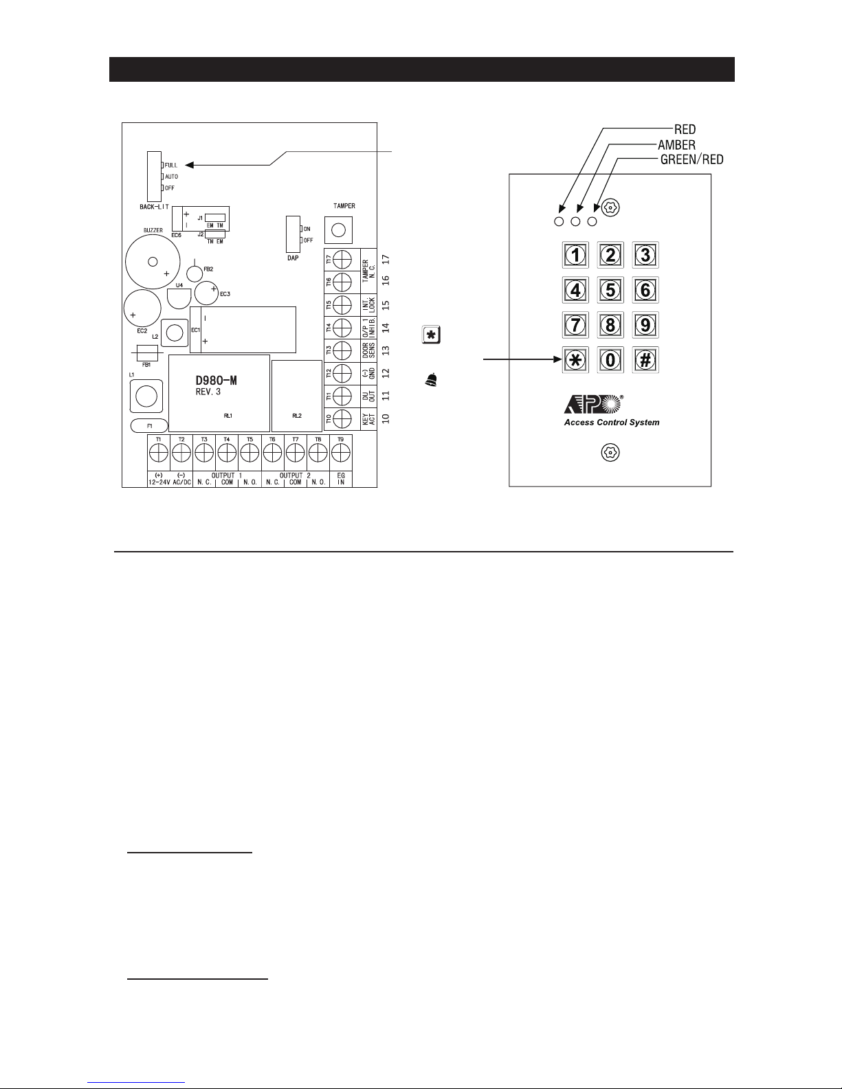
DESCRIPTION OF CONNECTION TERMINALS & INDICATORS
1 - 2 : 12-24V AC/DC --
3 - 4 - 5 : OUTPUT 1 --
N.O. contact for Fail-secureN.C. contact for Fail-safe.
6 - 7 - 8 : OUTPUT 2
a) Standard Version
●
●
●
CONNECTION TERMINALS
DK-9350 / DK9380
BACK-LIT JUMPER
STANDARD
VERSION
BELL BUTTON
VERSION
4

9 - EG IN --
10 : KEY ACT --
11 : DU OUT --
12 : GND (-) --
13 : DOOR SENS --
NOTE:
1) Door Auto Re-lock
2) Door Forced Open Warning
3) Door Propped-up Warning
4) Inter-lock Control
●
●
●
●
●
5

14 : O/P 1 INHIB. --
15 : INT. LOCK
16 - 17 : TAMPER N.C.
●
●
●
6

THE LED INDICATORS
MAINS (AMBER)
DOOR (GREEN & RED)
Auxiliary (RED)
BACK LIGHTING (BACK-LIT JUMPER SELECTION)
THE PACIFIER TONES & THE LED INDICATING SIGNALS
NOTE:
*
**
STATUS TONES*LED SIGNALS
1. In programming mode
---
1 Beep
2 Beeps
5 Beeps
Continuous Beeps
---
1 second Long Beep **
ON
1 Flash
2 Flashes
5 Flashes
Continuous Flashes
1 Flash in 2 seconds interval
---
2. Successful key entry
3. Successful code entry
4. Unsuccessful code entry
5. DAP jumper not replaced
6. In standby mode
7. Output relay activated
●
●
●
7

A) Enter Programming Mode with Master Code (Exit-Factory Master Code: 0 0 0 0)
NOTE:
B) System Refreshing –
C) Code Entries –
1) Recording Master Code and User Codes – (No Default Codes)
2) Recording Super User Code – (No Default Codes)
3) Recording Duress Codes – (No Default Codes)
4) Recording the Visitor Codes – (No Default Codes)
STANDARD PROGRAMMING SUMMARY CHART
8

(Default: Momentary, 1-second for all 3 outputs)
(default = 1 second)
(Default: 10 tries / 30 seconds)
(default)
F) Door Forced-Open Alarm – (Default: Disabled)
(default)
(Default: 1 long beep)
(default=1 second)
(default)
9

H) User Code Entry Modes (Auto or Manual) – (Default: Manual)
(Default: ON)
(default)
J) Main LED Flashing ON-OFF – (Default: Flashing)
K) Egress Delay & Warning – (Default: Instant, No warning)
(default)
L) Delay Time to Start Door Propped-up Warning – (Default: OFF)
(default)
M) Exit Programming Mode
(default)
(default)
10
Criteria for Programming
MUST
DO NOT
Enter and Exit Programming Mode
key.
Master Code
3. Exit the programming mode by pressing the
NOTE:
●
●
●
●
●
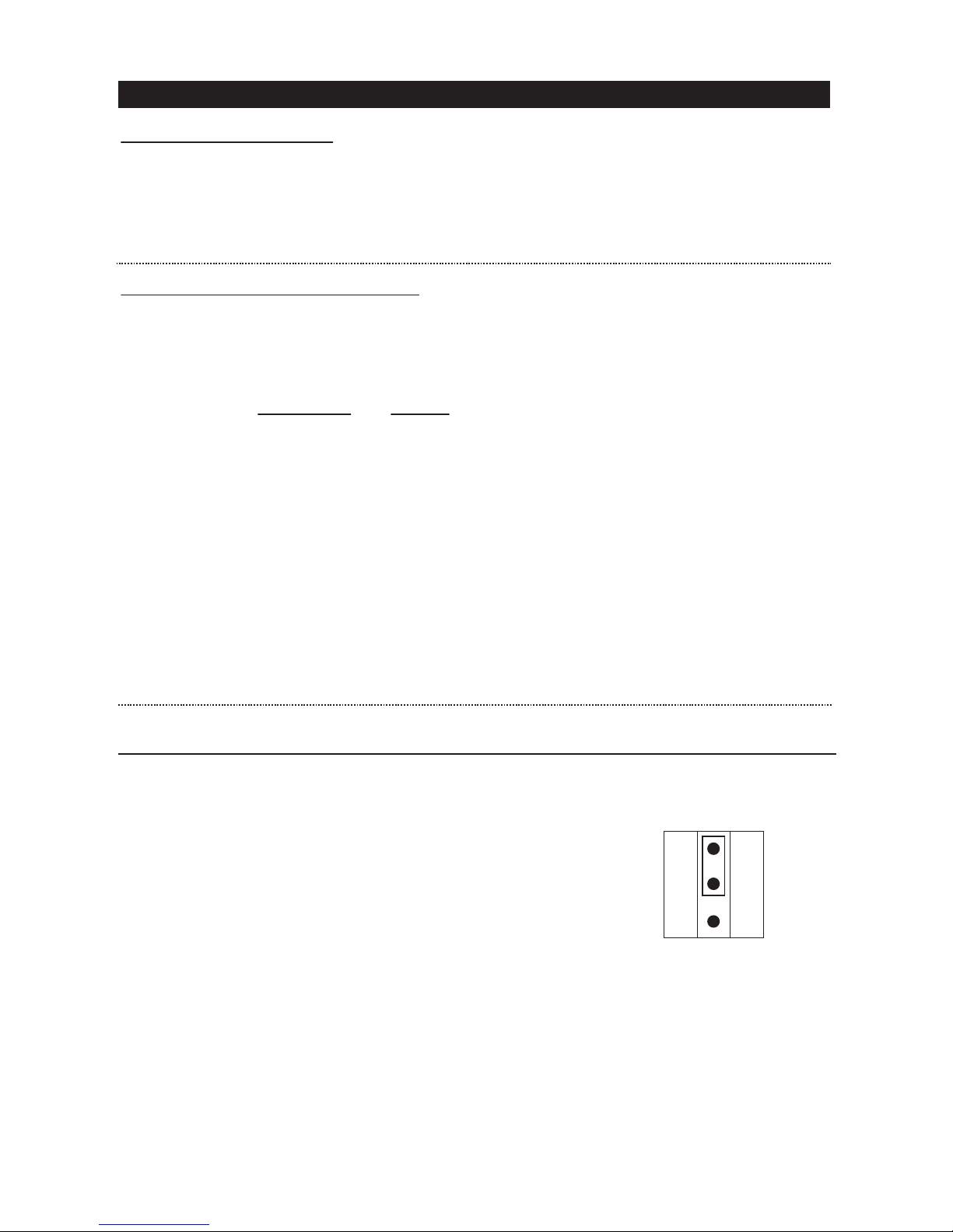
SETTING & PROGRAMMING
DAP
ON OFF
11

New Master Code
NOTE:
●
●
●
Programming Example :
0 0 0 0
2. Program a new Master Code 3 2 8 9 for the keypad:
NOTE:
●3 2 8 9
●
3 2 8 9
2. key to clear all the current stored data
except the Master Code:
NOTE:
●(default)
System Refresh (Complete Data Refresh) (Refresh Code 8901)
12

User ID Entry of Code
Output 1
Output 2
NOTE:
●
●00-99
●0-9
●
●
●
Programming Example :
3 2 8 9
2. Program an User Code 8 3 2 1 for output 1 ---------- One of the 100 user codes (user ID: 00-99,
taking ID = 01 as example):
3. Program an User Code 5 4 3 2 1 for output 2 ------- One of the 10 user codes (user ID: 0-9, taking
ID=1 as example):
Operaon (Manual Code Entry Mode)
NOTE:
13

Super User Code
NOTE:
●
●
●
●
Programming Example :
3 2 8 9
2. Program 2 5 8 0 as Super User Code:
Operaon :
14

NOTE:
●
●
●This feature is recommended for Fail-safe locks only.
●
REMARK :
●
●
●
●
●
●
3)
NOTE:
●
●
●
●
15

User ID Duress Code
NOTE:
●
●0-9
●
●
For example:1 3 5 7
3 3 5 7 1 3 5 8
●
●
Programming Example :
3 2 8 9
2. Program 3 3 5 7 as 1st Duress Code:
Program 2 3 9 8 0 as 2nd Duress Code --- if more user needs duress code:
Operaon :
NOTE :
●
●
16

One-Time
Time-Limit
User ID Entry of Code
NOTE:
●
●0-9
●
●
●
●
Programming Example :
3 2 8 9
2. Program a Visitor Code 1 3 7 8 at ID “0” for One-Time use:
3. Program a Visitor Code 2 3 0 8 9 at ID “1” with Time-Limit of 5 hours:
4. Program a Visitor Code 8 3 5 8 at ID “2” with Time-Limit of 10 hours:
Operaon :
17

Deleng Examples:
3289
a)
b)
c)
d)
e)
18

Time Length
A)
B)
C)
D)
NOTE:
●
● and 53
Programming Options for Outputs 1 & 2 (See “Programming Summary Chart” Secon D for more
informaon) :
Example:
8 3 2 18 3
5 4 3 2 15 4
Example:
5 4 3 2 15 4 3
9 2 7 0 5 39 2 7
19

Operaon :
8 3 2 1
5 4 3 2 1
5 4 3 2 1
NOTE:
●The purpose of the accelerated Code --
●
Super User Code
Super User Code
Programming Examples:
3 2 8 9
2. Set Output 1 in momentary mode of 5 seconds:
3. Set Output 2 in Start / Stop Mode; OR
4. Set Output 2 in Start / Stop Mode with 3-digit Accelerated Start Code:
20
This manual suits for next models
3
Table of contents
Other Velleman Keypad manuals

Velleman
Velleman HAA2890 User manual

Velleman
Velleman HAA85WP User manual

Velleman
Velleman PC50001 User manual

Velleman
Velleman HAA2850 User manual

Velleman
Velleman HAA263D User manual

Velleman
Velleman etiampro HAA2866N User manual

Velleman
Velleman CTC1000KP User manual

Velleman
Velleman HAA2866 User manual

Velleman
Velleman PCUSB29 User manual

Velleman
Velleman HAA85 User manual


