GLT-299-7-10 Rev.0
Jun 12, 2018
4
Section 5 – GENERAL OPERATION
VDOT-S6 Base is controlled by Fire Alarm Control Panel series for emitting alarm and selecting sound pattern.
The panel initiates the sound of the base individually or collectively and also the panel selects the sound from 4
patterns which are continuous, march, ANSI 3 temporal and 4 temporal according to a “Job data” (site-specific
data). Only ANSI 3 temporal pattern shall be used for UL Listed applications.
When the base is disconnected from SLC, the control panel indicates fault warning. Meanwhile, if the fault
warning caused by open or short circuit on the AUX. power circuit is required to be indicated on the panel, use
PCE and VDOT-MiniIP as described in Section 8.
Section 6 – ADDRESS SETTING
The VDOT-S6 Base requires compatible addressable communications to the control panel in order to function
properly. All sounder bases have random addresses from the factory before installation. The VDOT-AD2 Address
Programmer is used for setting the address between 1 and 254 decimal of all devices prior to installation. See
Annex A for the handling. Once addressed, connect to Fire Alarm Control Panel series.
Note: Address setting for VDOT-S6 Base needs to be executed in the condition of being unwired to SLC.
Section 7 – INSTALLATION
The product must be installed in accordance with the applicable NFPA standards, local codes and jurisdictional
authorities. Failure to follow these instructions may result in failure of the detector to report an alarm condition.
Note: ZETA ALARMS LIMITED is not responsible for the product which is improperly installed, maintained and
tested.
The sounder base is designed to be mounted to 3-1/2” octagonal, 4” octagonal or 4” square electrical conduit box.
Before installing the product, check the continuity, polarity and insulation resistance of all wiring. Check that siting
is in accordance with the site system drawings and conforms to all applicable local codes such as NFPA 72.
In normal use, the VDOT-S6 Base will be installed at ceiling level or wall position. Please refer to specific detector
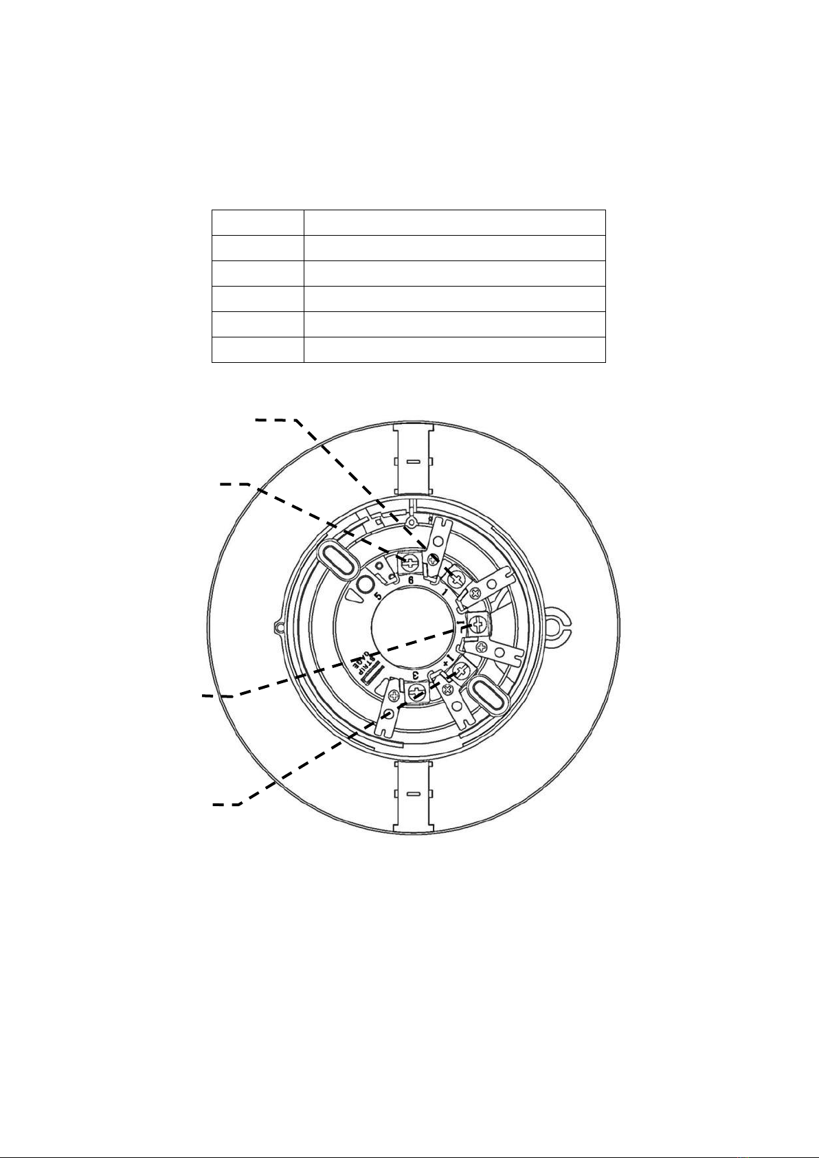
instruction manual for details. Pass the field wiring through the cable opening in the center and from the rear of
the base. Install the base to the electrical box with screws via the base mounting holes. Connect the field wiring to
the base terminals, as detailed in Figure 5.
Install the detector head by inserting it into the base and turning clockwise until the notch in the detector rim aligns
with base locking screw. To avoid unauthorized removal, turn the locking screw counterclockwise until the screw
extends out about 4 mm (3/16”) from the rim of the base (See Figure 4).
Note: If the detector is installed on a high ceiling where a tool (ladder, etc.) is needed, it is not recommended to
use the locking screw.