Venset TS700A User manual

Electric TV Lift, TS700A & TS1000A
1
INSTALLATION INSTRUCTIONS
CONTENT:
1. Important safety instructions.
2. Specifications and main dimensions.
3. Parts included.
4. Installation.
5. Adjusting the stroke length of the lift.
6. Declaration of conformity.
WARNING
WARNING: FAILURE TO COMPLY WITH OR OBSERVE ALL
ASSEMBLY, SAFETY AND OPERATION INSTRUCTIONS
AND WARNINGS REGARDING THE USE OF THIS PROD-
UCT MAY RESULT IN SERIOUS BODILY INJURY.
No. #324360.3
TS1000A
TS7
00A
Load with
min. 5 kg

Electric TV Lift, TS700A & TS1000A
2
1. Important safety Instructions.
Use the following safety guidelines to help protect your lift from potential damage and to en-
sure your own personal safety.
•Read all the installation instructions before testing or installing your lift.
•Read and follow all safety instructions.
•Keep remote control and manual rocker switch out of reach of children.
•To prevent bodily injury keep hands and clothing away from the lift while the lift is in
operation.
•Before installing the lift or working with its connections, unplug the lift from the elec-
tricity main supply.
•Do not install the lift, power supply or R.F. module in places subject to high tempera-
tures for example near a radiator, or heating vent.
•The TV lift must only be mounted in a dry area and it must be ensured before use that
the lift is safe or protected from liquid contact or spillage.
•To avoid damaging the power supply, R.F. module and power cord, do not put any-
thing on it or place it where it could become damaged.
•Unplug the lift in the following conditions:
When the power cord or plug is damaged or frayed.
If the lift, power supply or RF module has been exposed to rain or wa-
ter or any liquid contamination whatever.
If the lift exhibits a distinct change in performance, indicating a need
for attention.
•MANUFACTURES who build this lift into other products or use it with other products,
MUST make sure to prevent bodily injury. The MANUFACTURER of the final product
is responsible to give the end user proper warnings and instructions for use.
CAUTION: Before you begin any of the Installation procedures
(4. Installation.)
,
read and follow the warnings and safety instructions on this page.
WARNING ! THIS IS NOT A TOY !
WARNING ! CHILDREN SHOULD NOT OPERATE LIFT OR
REMOTE CONTROL !

Electric TV Lift, TS700A & TS1000A
3
2. Specifications and main dimensions.
Materials and weights: Steel, black powder coated - Weight ~ 17/23 kg
Max. working loads:
65 kg (by standard installation)
29 kg (when lift is mounted upside down)
100 kg peak load
Duty cycle: 10% by 50% of working load or max 2 min. continuously
Operation: Remote and rocker switch
Voltage:
Standby Consumption: 100-240 VAC / 50/60Hz
< 1 Watt
Above specifications may vary depending on local temperature, humidity and input voltage.
Main dimensions, TS700A [mm]:
VESA, TS700A:
400x400, 400x200, 400x100
300x300 (see venset.com for
mounting instruction)
200x200, 200x100
100x100

Electric TV Lift, TS700A & TS1000A
4
Main dimensions, TS1000A [mm]:
VESA, TS1000A:
600x400, 600x200, 600x100
400x400, 400x200, 400x100
300x300, 200x200, 200x100

Electric TV Lift, TS700A & TS1000A
5
3. Parts included.
Lift unit ( #1 )
Lid lifter ( #2 )
Lift brackets ( #3 )
TV mounting brackets ( #4 ) (TS1000A only)
R.F. Module ( #5 )
Remote control ( #6 )
AC input wire, country configured ( #7 )
Power supply bracket ( #8 )
Rocker switch ( #9 )
Power supply ( #10 )
Lift unit ( #1 )
Lid lifter ( #2 )
Lift brackets ( #3 )
(smaller for TS700A)
TV mounting
brackets ( #4 )
(TS1000A only)
R.F. Module
( #5 )
Remote con-
trol ( #6 )
AC input wire, coun-
try configured ( #7 )
Power supply mounting
bracket ( #8 )
Power supply ( #10 )
Rocker switch ( #9 )

Electric TV Lift, TS700A & TS1000A
6
4. Installation.
1) Remove all contents from packaging and compare with parts list.
2) Place the lift unit (#1) on e.g. the back panel of the cabinet** in a location that will al-
low full up and down movement of the lift.
3) Fasten the unit securely to the cabinet. Screws must be appropriate for the material
being used.
4) Connect the plugs from lift unit (#1) and power supply (#10) to R.F. Module (#5).
Please also refer to the separate user instruction for the remote unit, next page.
5) Mount rocker switch (#9) in an easy location by cutting a ø30 hole and pressing the
switch into place. Secure excess wire to keep away from moving parts.
6) Plug the power cord into main electrics and add minimum 5kg and operate manual
rocker switch. See troubleshooting guide on www.venset.com, click “support”.
Helpful hint: Mount TV lift and electronics to plywood panel and attach to inside back of cab-
inet using appropriate number of screws. This allows all components to be removed from the
cabinet if necessary. If this is not possible, create an access panel to the electronics.
** Aim to create access for wear and tear replacement stroke service.

Electric TV Lift, TS700A & TS1000A
7
User instruction, RF remote system
Installation
oconnect the power supply and
the motor unit to the remote re-
ceiver. 2 different plug sizes
make this connection only possi-
ble to make in the right way
oafter having connected the plugs,
the blue light will be lit
opush the emitter buttons and the
motor unit will move up and
down
ofor stopping the motion one of
the buttons need to be pushed
Learning
oif the remote receiver does not respond when pushing the emitter buttons, reset the
receiver. After that, code the emitter and receiver together again
Coding
opush the learner button on the receiver for less than 1 sec.
opush one of the emitter buttons
othe red light will start flashing
opush one of the emitter buttons again and the red light will turn off
othe units now are coded together with a unique code
Reset
opush and hold down the learner button on the receiver for 10 sec. (will be reset when
the red light turns off).
External rocker switch
othe external rocker switch can be connected to the receiver, if a fixed operation unit is
required.
Trouble shooting
ocheck the plug connections
ocheck whether the blue light is on
oreset the receiver and make a new coding
oalways test the lift on the manual rocker switch
osee www.venset.com , click “support”

Electric TV Lift, TS700A & TS1000A
8
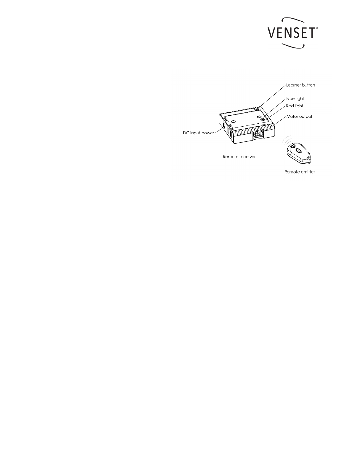
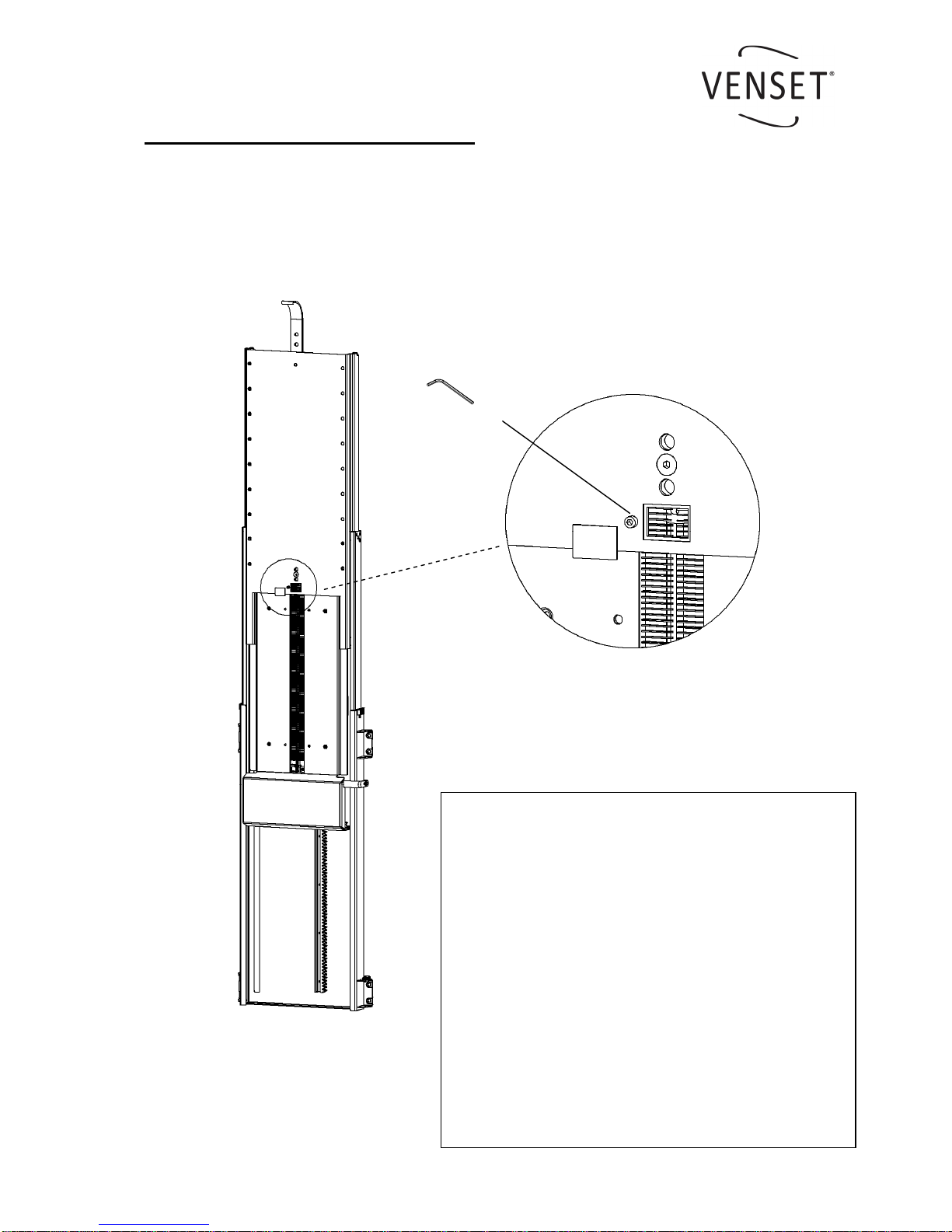
Setting options for operation of lift
This remote system has 4 ‘jumpers’ inside the remote receiver box, these can be lifted and
positioned ‘Left’ or ‘Right’ depending of how the functionality of the lift should be.
Jumper A – Power safety cut off time
Default ‘Left’ = 60 seconds. If moved to right
position then the lift will power off automatical-
ly after the motor has run for 20 seconds.
Jumper B – Remote emitter function
Default ‘Right’ = the buttons on the emitter
only need to be pushed once for activation. If
moved to the left position then the emitter
button will need to be held down during the
operation of the lift, ie..for use where a higher
level of safety may be required.
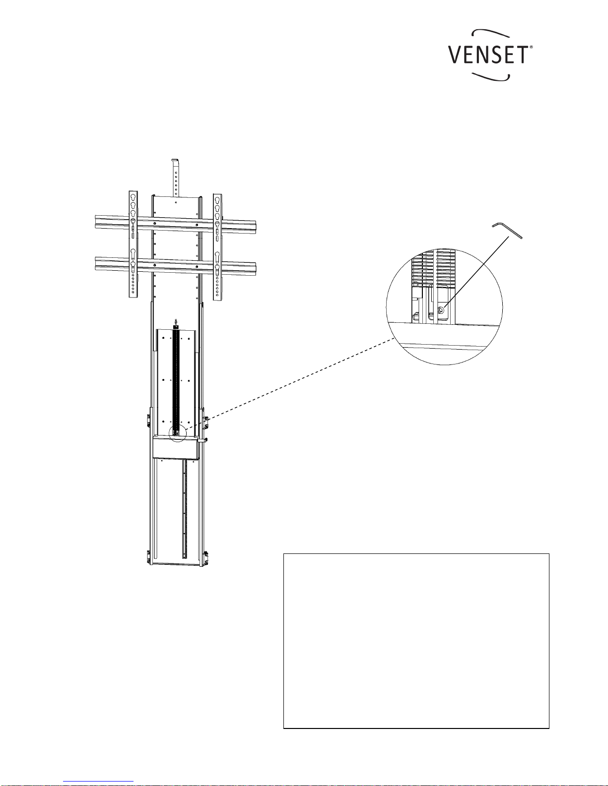
Jumper C – Auto-reverse time (type A lifts only)
Default ‘Right’ = a reverse period of 1 second. If moved to the left position, the reverse time
is reduced to 0.6 of a second.
Jumper D – Using the lift upside down (type A lifts only)
Default ‘Right’ = normal operation in an upright position ie.. to raise a TV up and down from a
floor standing cabinet. If moved to the left position the reverse function will work with the lift
mounted up-side down ie.. to lower down and up a TV from the bottom of a wall mounted
cabinet. If no reverse function is required then remove the jumper.
Change of battery in emitter (battery type 27A/12V)
oremove lid on back side
olift up battery
oplace new battery
Please be aware that storing emitter in environment with high humidity may damage the
product.
FCC Statement
This device complies with Part 15 of the FCC rules. Operation is subject to the following two
conditions; 1) This device may not cause any harmful interference and 2) This device must
accept any interference received, including interference that may cause undesired operation.

Electric TV Lift, TS700A & TS1000A
9
5. Adjusting the stroke length of the lift.
Adjusting the bottom stop:
The bottom stop can be adjusted to any preferred height, e.g. if you don’t want the lift to go
all the way down into the cabinet. You can adjust just one or both end stops.
1. The more you move the glider down the cable
the earlier the lift will stop on the down stroke
as the end stop switch will be triggered sooner.
2. Raise the lift up to the just above lowest posi-
tion that you want it to reach on the down
stoke.
3. Remove the small plastic cover plate (see fig.1)
and you will see the glider on the cable.
4. Use a 2.5mm Allen key to loosen the screw in-
side the glider. (see fig.1)
5. Move the glider down the cable accordingly and
tighten the screw securely.
6. Replace the plastic cover plate, the glider will
no longer be in this window.
7. Test the lift fully up and down and check the
desired bottom stop position is as you require.
Fig. 1

Electric TV Lift, TS700A & TS1000A
10
Adjusting the top stop:
The top stop can be adjusted to any preferred height, e.g. if you don’t want the lift to go all
the way up out of the cabinet. You can adjust just one or both end stops.
1. The more you move the glider down the cable
the earlier the lift will stop on the up stroke as
the end stop switch will be triggered sooner.
2. Raise the lift up to full height.
3. You will see the glider on the cable below the
nylon brushes (see fig.2)
4. Use a 2.5mm Allen key to loosen the screw in-
side the glider. (see fig.2)
5. Move the glider down the cable accordingly and
tighten the screw securely.
6. Test the lift fully up and down and check the
desired top stop position is as you require.
Fig. 2

Electric TV Lift, TS700A & TS1000A
11
6. Declarations of conformity.

Electric TV Lift, TS700A & TS1000A
12
The information in this document is subject to change without notice.
Other manuals for TS700A
2
This manual suits for next models
1
Table of contents
Other Venset TV Mount manuals
Popular TV Mount manuals by other brands

Sony
Sony KDL22L5000 - BRAVIA L Series Additional information for Using

aspenhome
aspenhome I240-487-RIV Assembly instructions

LEGRAND
LEGRAND SANUS BIWLF128-B3 instruction manual

Philips
Philips SBC VS010 Specification sheet

Monster Mounts
Monster Mounts MF642 installation manual

peerless-AV
peerless-AV IWB680-W manual