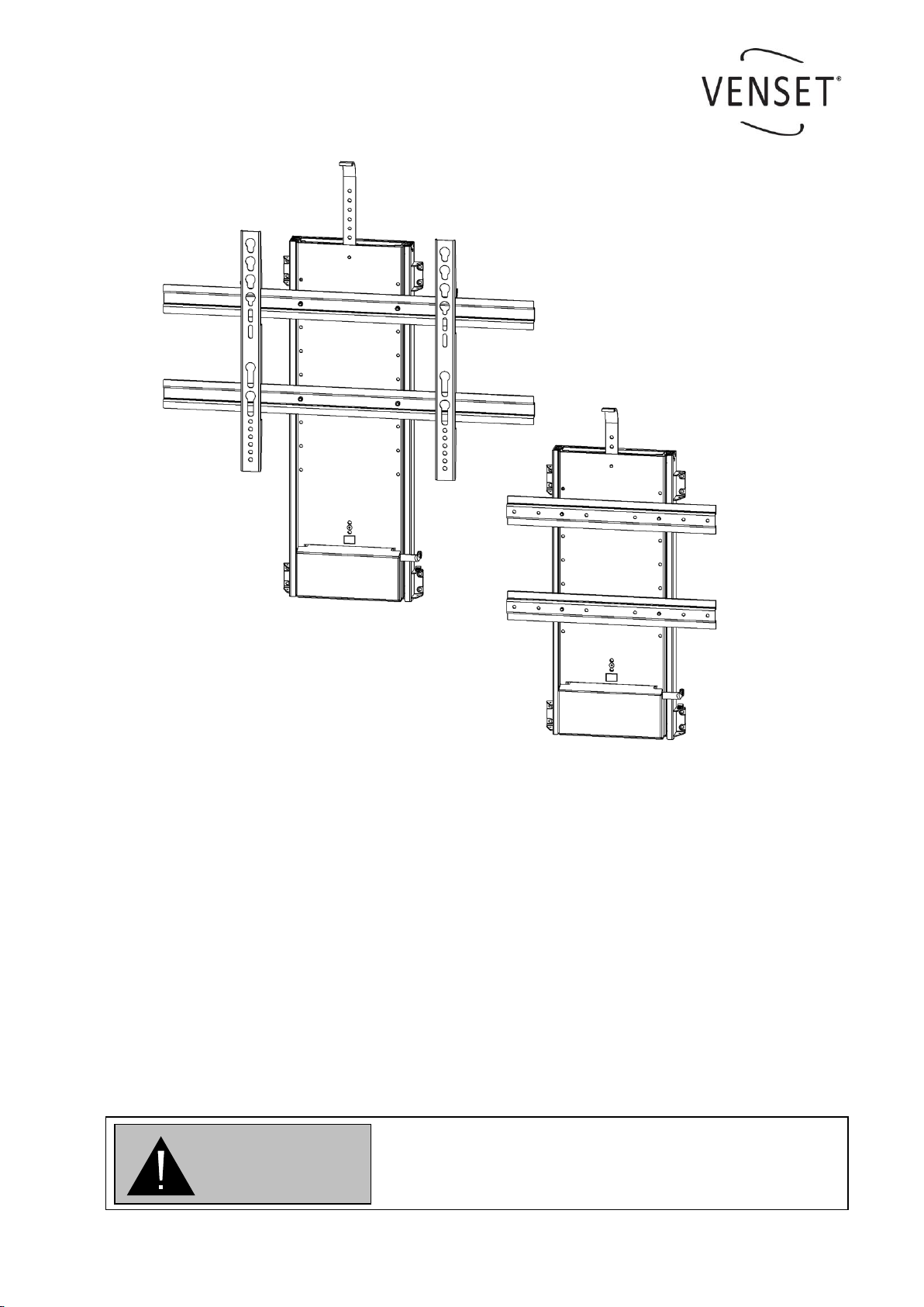
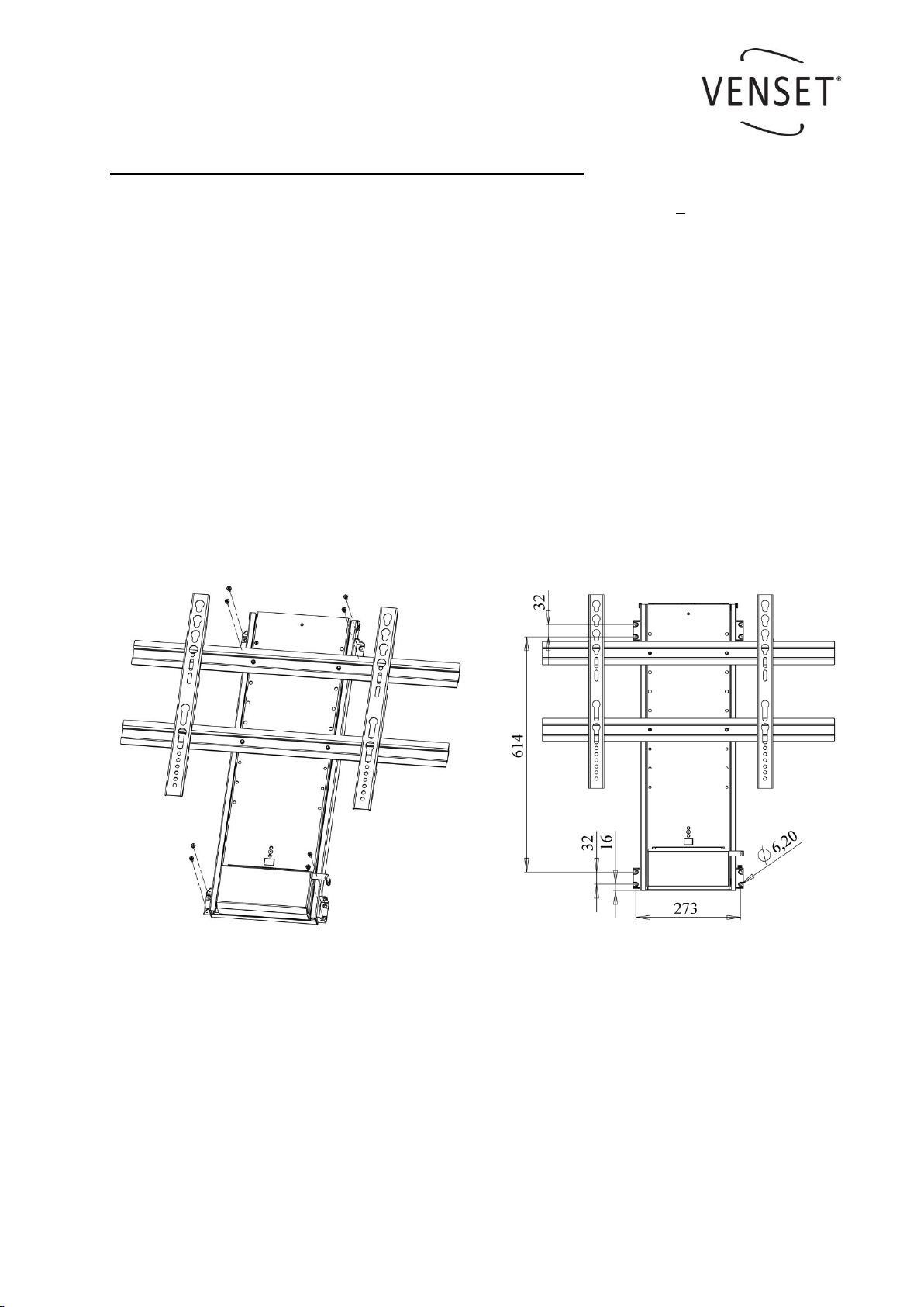
Electric TV Lift, TS700C & TS1000C
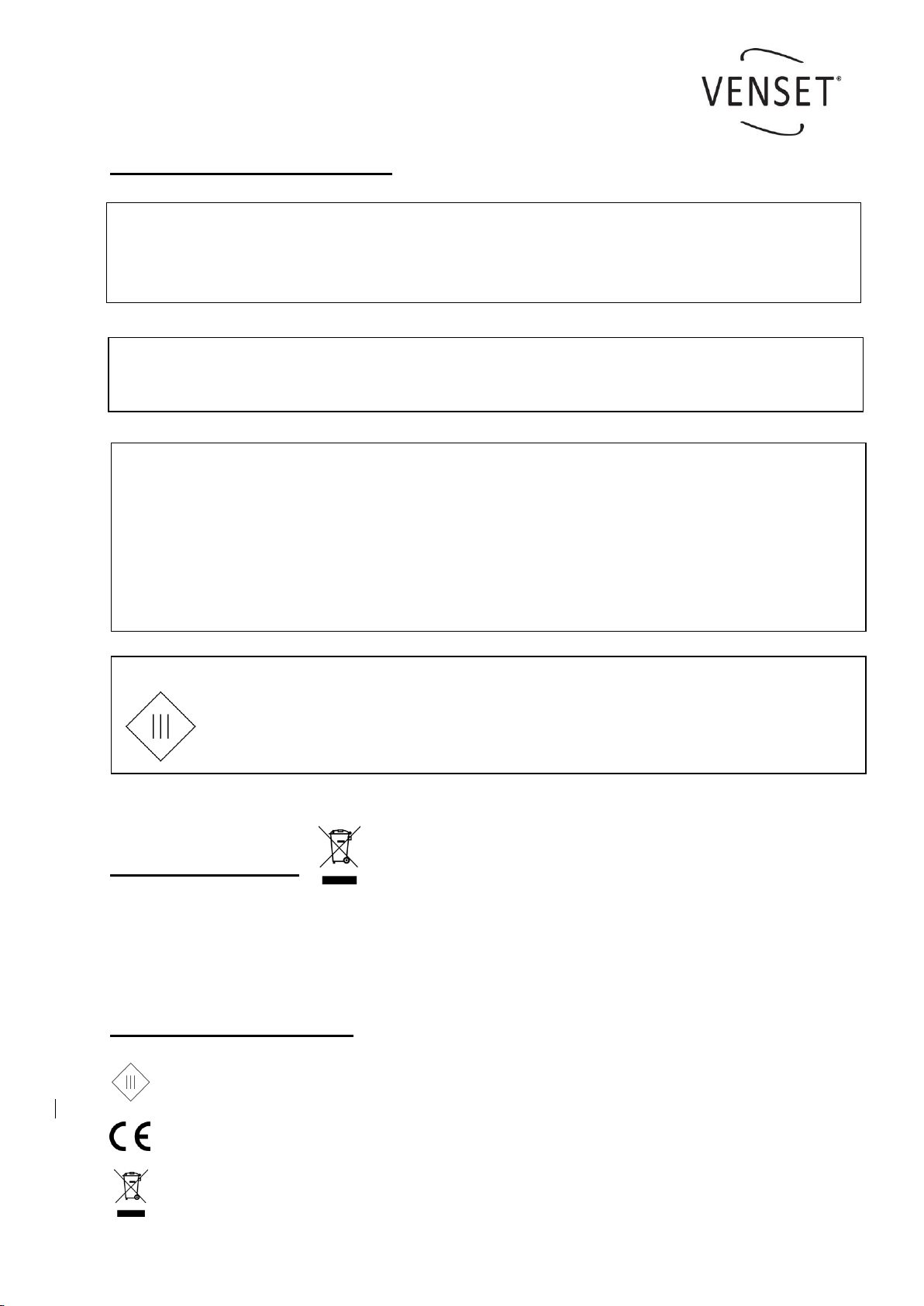
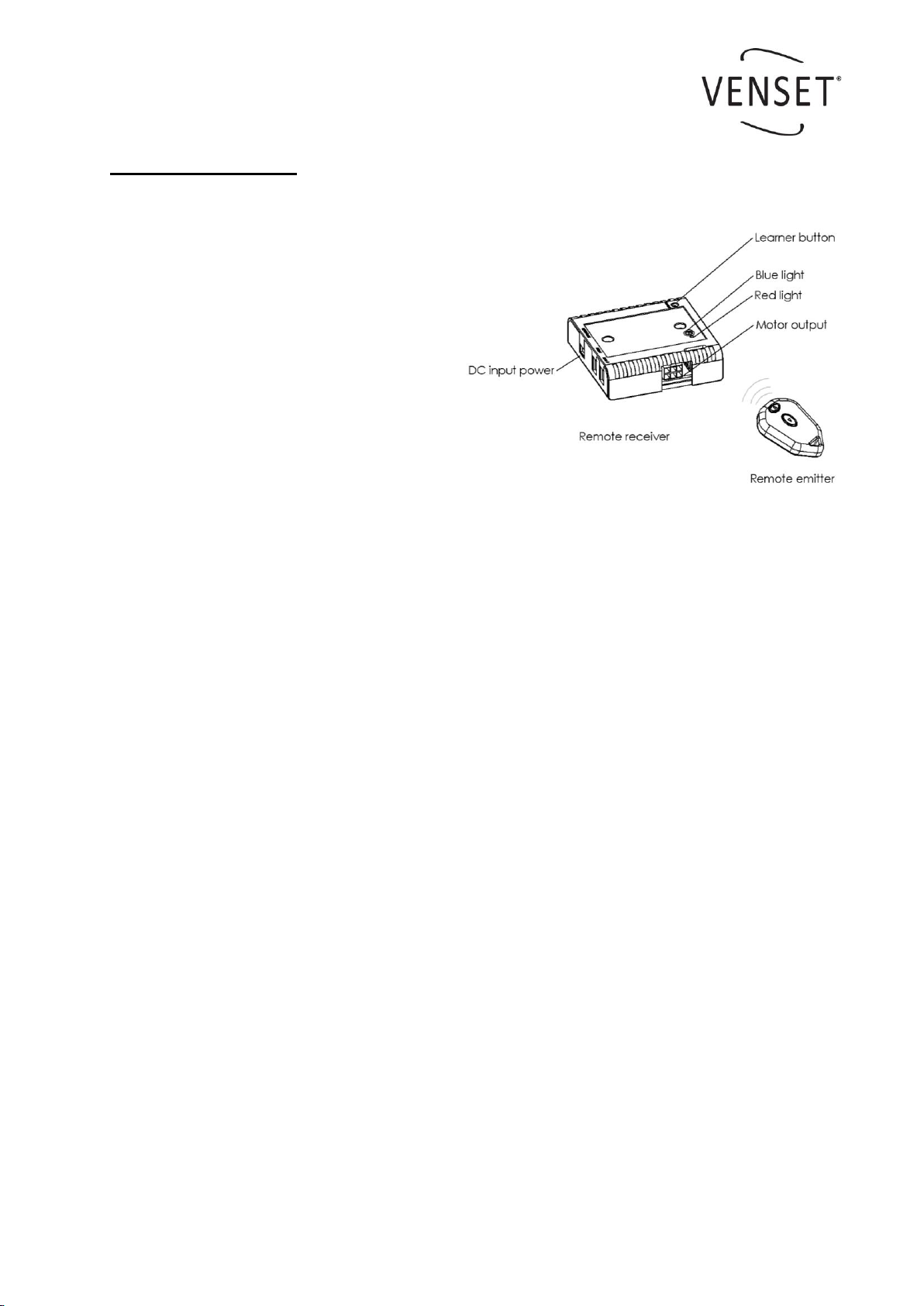
5. RF remote system.
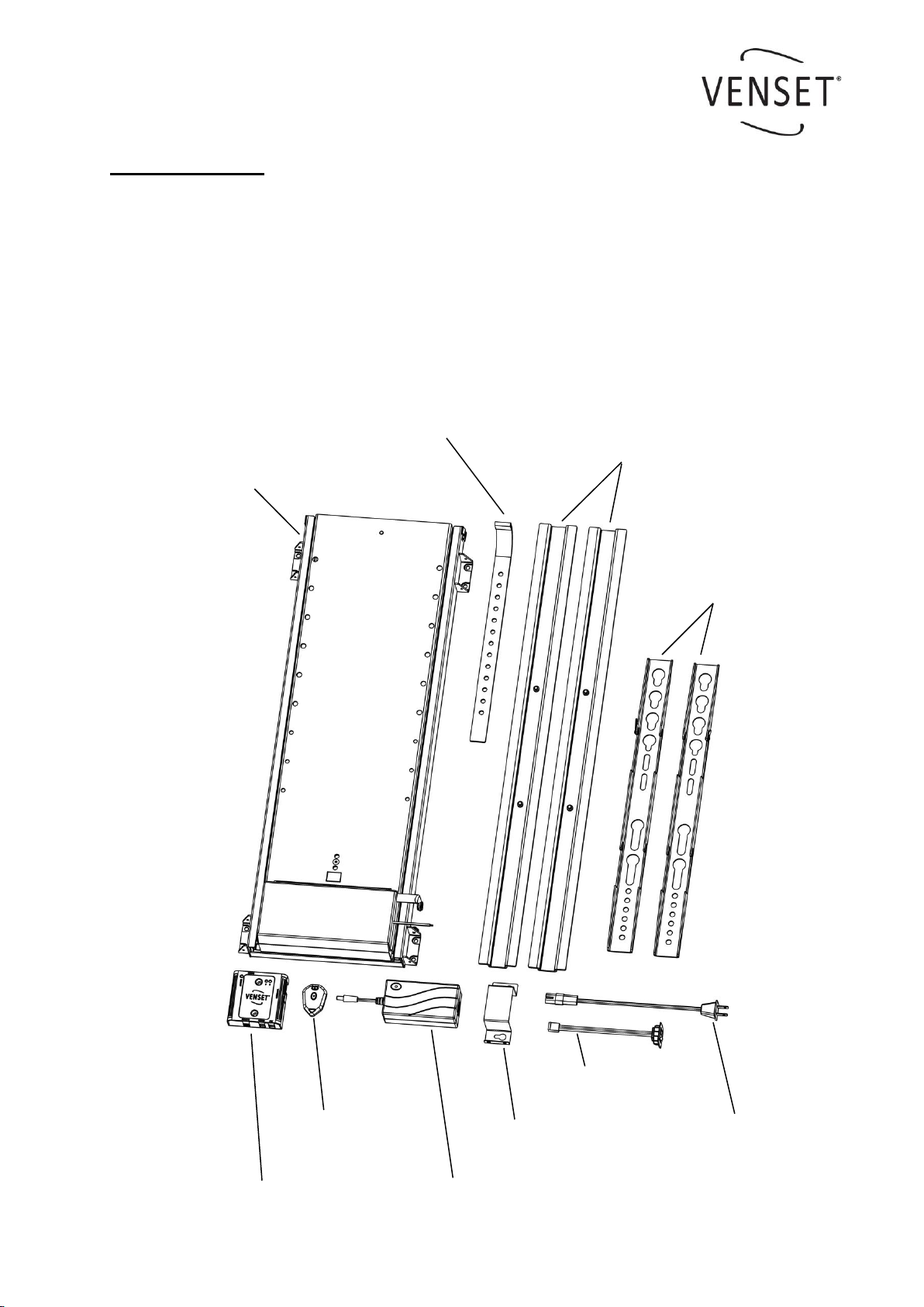
Installation
oconnect the power supply and
the motor unit to the remote re-
ceiver. 2 different plug sizes
make this connection only possi-
ble to make in the right way
oafter having connected the plugs,
the blue light will be lit
opush the emitter buttons and the
motor unit will move up and down
ofor stopping the motion one of the
buttons need to be pushed again
Learning
oif the remote receiver does not respond when pushing the emitter buttons, reset the
receiver. After that, code the emitter and receiver together again.
oit is possible to code up to 10 remote emitters to the remote receiver.
Coding
opush the learner button on the receiver for less than 1 sec.
opush one of the emitter buttons
othe red light will start flashing
opush one of the emitter buttons again and the red light will turn off
othe units now are coded together with a unique code
Reset
opush and hold down the learner button on the receiver for 10 sec. (will be reset when
the red light start to blink).
External rocker switch
othe external rocker switch #9 can be connected to the receiver, if a fixed operation
unit is required. This should always be fitted or accessible in case the RF handset or
battery fails.
Trouble shooting
ocheck the plug connections
ocheck whether the blue light is on
oreset the receiver and make a new coding
oalways test the lift on the manual rocker switch
osee www.venset.com , click “support”