manuals.online logo
Brands
  1. Home
  2. •
  3. Brands
  4. •
  5. Vents
  6. •
  7. Control Panel
  8. •
  9. Vents VENTS RTS-1-400 User manual

Vents VENTS RTS-1-400 User manual

HEAT REGULATOR
"VENTS RTS-1-400"
"VENTS RTSD-1-400"
(with remote controller)
DESTINATION
Heat regulator is intended for air heating or cooling with the help of control SPST or SPDT mixers with electrical
servo drive, control of 3-speed fan.
BASIC TECHNICAL SPECIFICATIONS
Power supply: 220 V AC, 50/60 Hz
Output capacity for contacts 2, 3, 4: not more than 2.0 A
Output capacity for contacts 5, 6: not more than 0.1 A
0 0
Temperature setting range: +5 C - +37 C
Overall dimensions: 86x86x15 mm
-Illuminated LC display
-Temperature setting is carried out simply by pressing buttons with "up" and "down" arrows
-On the display, setting temperature and temperature in the premise are displayed simultaneously
-Maintaining temperature to within 1 set degree
-Automatic switching of 3-speed gan
-Saving of user settings after switching off power supply
-Availability of remote controller (model RTSD-1-400)
DESCRIPTION OF DESIGN
Front panel (Fig.1)
Display 1
"power" button 2
mode selection button (HEATING, COOLING) 3
fan speed selection button (HIGH, MEDIUM, LOW, AUTO) 4
"night" mode selection button 5
increase of set value of temperature 6
decrease of set value of temperature 7
IR receiver 8 (for model RTSD-1-400)
Display (Fig.2)
shows that heat regulator is switched to "night" mode 9
shows that heat regulator is switched to cooling mode 10
shows temperature in the premise or set temperature 11
shows set temperature or temperature in the premise 12
shows whether valve with drive is switched or not 13
shows selection of fan speed 14
shows that heat regulator is working in heating mode 15
COMPLETE SET
The delivery set includes:
-heat regulator 1
-remote controller 1 (only for model RTSD-1-400)
-certificate
SET
ROMM
ON
OFF
MODE
AUTO
FAN
OFF
10
11
12
13
15
2
3
4
5
6
1
7
8
9
14
Fig.1
Fig.2
night
mode temperature
"up"
temperature
"down"
heating
low
auto-control
power
cooling
medium
high
REMOTE CONTROLLER
For control of operation of heat regulator with the help of remoter controller, point the remote controller to the front
panel of heat regulator from the distance of not more than 4 m.
In the course of long-term operation, discharge of power supply element is possible. In this case, replacement of
power supply element is required. To do this, pull out holder of the element from the bottom part of remote
controller and replace power supply element, observing polarity.
STORAGE RULES
It is necessary to store heat regulator in manufacturer's package in the ventilated premise at temperature from
0 0 0
+5 C to +40 C and relative air humidity of not more than 80 % (at T = 25 C).
MANUFACTURER'S WARRANTY
The manufacturer, "Vents" Joint-Stock Company, guarantees normal operation of heat regulator during 12 months
from the date of sale through retail trade network, in case of observance of transportation, storage, assembling and
operation rules. The warranty does not cover the goods with signs of mechanical damages.
If note about date of sale is absent, warranty period is started from the date of production. If any failures in
operation of heat regulator through manufacturer's fault are detected during the warranty period, the consumer has
a right to replace heat regulator at the manufacturer, according to Clause 14, Item 9 of the Law of Ukraine "About
Protection of Consumers".
Replacement is carried out by the address: 01030, Kiev, M.Kotsiubinsky Str. 1
REMOTE CONTROL
ACCEPTANCE CERTIFICATE
Heat regulator of speed is accepted as ready for operation
Model
"Vents RTS-1-400"
"Vents RTSD-1-400"
(with the remote controller)
Date of production
Acceptance stamp
Sold
(name of trade enterprise, stamp of the shop)
Date of sale
V21EN -02
If no button is pressed during 20 seconds, heat regulator will switch off.
Menu item 1: Accuracy of maintaining temperature. On the display, the text "Temp adjust" will appear. The default
value is 0; it is blinking in configuration menu. Any value from "-3" to "+3" may be selected. You may set on the
display the temperature of the premise of up to 3 degrees higher or lower than the set value.
Menu item 2: Entering upper limit of temperature setting. On the display, 37 0C is represented, that is default value
of upper limit, set by the manufacturer. Using "+" and "-" button, the upper limit may be set in the range from 26 0Ñ
to 37 0C.
Menu item 3: Entering lower limit of temperature setting. On the display, 5 0C is represented, that is default value of
lower limit, set by the manufacturer. Using "+" and "-" button, the lower limit may be set in the range from 5 0Ñ to
26 0C.
Menu item 4: Control of fan. On the display, "ON" is represented, that is default value, set by the manufacturer.
Using "+" and "-" button, "ON" or "OFF" may be selected. If "ON" is selected, heat regulator will switch the fan to
the set speed and will not stop it until mode selection button or fan speed selection button is pressed. When "OFF"
is selected, if, during heating, set temperature is lower than room temperature, or, during cooling, set temperature
is higher than room temperature, heat regulator will stop the fan and will stay in this mode until mode selection
button is pressed.
1
holder of power
supply element
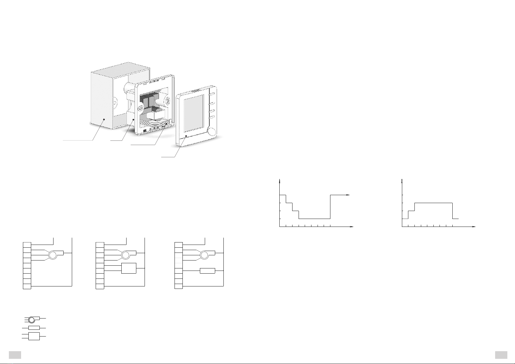
INSTALLATION OF HEAT REGULATOR
ATTENTION! THERE IS A HAZARD OF ELECTRIC INJURY!
Prior to dismantling or installation of existing heat regulator, de-energize wiring being connected
IMPORTANT:
Installation of terminal box in the premise must comply with local and national building norms and regulations.
Connection to supply network must be carried out via switch with gap between open contacts of not less than
3 mm for all poles, built in fixed wiring.
Activities on installation of heat regulator must be carried out by qualified specialist
that have appropriate admission.
1 . Fix terminal box to the wall
2 . Remove packaging material from heat regulator. Carefully disengage front control panel from the body.
Excessive effort may lead to damage of heat regulator.
3 . Connect wires to the terminals of heat regulator according to the connection layout.
4 . Put the body into 86x86 mm terminal box.
5 . With the help of two assembling screws, attach the body of heat regulator to the terminal box.
6 . With the help of level, adjust position of body of heat regulator, then tighten fixing screws
(leveling effects only the appearance and has no influence on operation of heat regulator).
7 . Mount front panel on the body of heat regulator, pressing it until the click.
CONNECTION LAYOUT
3-speed fan
1
2
3
4
5
6
7
8
9
LN
HI
MED
LOW
ON
1
2
3
4
5
6
7
8
9
LN
HI
MED
LOW
OFF
ON
1
2
3
4
5
6
7
8
9
LN
HI
MED
LOW
Ventilation with
heating and cooling
Fig.3
terminal
box
body
front
panel
connection
of front panel
220 V~ 220 V~ 220 V~
Ventilation with
heating and cooling
3-wire system of SPDT valves
Ventilation with
heating and cooling
2-wire system of SPST valves
+1
+2
0С
0,5 h 1 h 2 h 3 h 4 h 5 h 6 h 7 h 8 h
0С
-3
-3
-3
set
temperature
0,5 h 1 h 2 h 3 h 4 h 5 h 6 h 7 h 8 h
Set temperature automatically
decreases
Timer is switched off
in "night" mode and
returns to the last set point
Heating mode
temperature
time
0С
0С
0С
PECULIARITIES OF FUNCTIONING OF NIGHT MODE
Heat regulator is set to cooling mode: For smooth change of temperature, an hour after setting "night" mode, set
temperature automatically increases by 1 degree, in two hours by two degrees; then, the temperature will be
maintained at this level during 8 hours until timer is switched off. After switching off timer, set point will be
automatically returned to initial value.
Heat regulator is set to heating mode: For more smooth change of temperature, half an hour after setting "night"
mode, set temperature automatically decreases by 1 degree, in two hours by two degrees; then, the temperature
will be maintained at this level during 8 hours until timer is switched off. After switching off timer, set point will be
automatically returned to initial value.
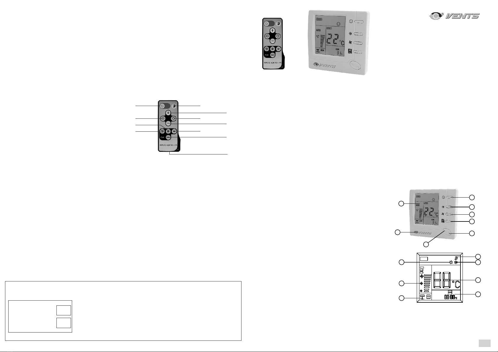
OPERATION OF HEAT REGULATOR
Switch on the heat regulator, pressing "power" button (2).
Press fan speed selection button. On the display, one of the characters (14 in Fig.2) will appear or AUTO. This
means that fan will rotate at HI (high), MED (medium), or LOW (low) speed or in AUTO (automatic mode).
If AUTO mode is selected, fan rotation speed will change, depending on difference between actual temperature
in premise and set temperature. If temperature in the premise is by more than 3 degrees higher than set
temperature during cooling and by more than 3 degrees lower than set temperature during heating, fan will
operate at the highest speed. If temperature in the premise is by 2 3 degrees higher than set temperature during
cooling and by 2 3 degrees lower than set temperature during heating, fan will operate at medium speed. If
temperature in the premise is by 0 1 degrees higher than set temperature during cooling and by 0 2 degrees
lower than set temperature during heating, fan will operate at low speed.
Operation of heating system
Using mode selection button, select heating mode (15 in Fig.2).
Press "+" to increase the value of set temperature. If temperature in the premise is lower than set temperature,
the heating system will start operation.
Press "-" to decrease the value of set temperature. If temperature in the premise is higher than set temperature,
the heating system will stop operation.
Operation of cooling system
Using mode selection button, select cooling mode (10 in Fig.2).
Press "-" to decrease the value of set temperature. If temperature in the premise is higher than set temperature,
the heating system will start operation.
Press "+" to increase the value of set temperature. If temperature in the premise is lower than set temperature,
the heating system will stop operation.
Operation of "night" mode
Press "night" mode selection button (5 in Fig.1). Symbol of "night" mode (9 in Fig.2) will appear. This mode will
active during 8 hours, at that, heat regulator will control heating or cooling according to the chart (see below).
Press "night" mode selection button once more, appropriate symbol will disappear; this means cancellation of
"night" mode operation.
3
ADJUSTMENT OF CONTROL MODES
Adjustment of control modes allows setting certain performance characteristics of heat regulator according to your
requirements.
Switch off heat regulator, pressing "power" button, then press and hold "night" mode selection button (5, Fig.1) at
least 4 seconds until the display switches on. This means that you have entered the first menu option of setting
mode. There are 4 menu options, that is represented on the display. Selection of appropriate menu option is made
by pressing (5) button. In each menu option, press "+" or "-" button to change settings. To quit the menu and return
to normal operation mode, switch off heat regulator, pressing "power" button and, then, switch it on again.
2
2-wire SPST valve
3-wire SPDT valve
temperature
set
temperature
Set temperature automatically
increases
Cooling mode
Timer is switched off
in "night" mode and
returns to the last set point
time

Other manuals for VENTS RTS-1-400

1

This manual suits for next models

1

Other Vents Control Panel manuals

Vents KV TwinFresh Wi-Fi User manual

Vents

Vents KV TwinFresh Wi-Fi User manual

Vents A25 User manual

Vents

Vents A25 User manual

Vents PU SENS 01 A11 User manual

Vents

Vents PU SENS 01 A11 User manual

Vents PU SENS 01 A11 User manual

Vents

Vents PU SENS 01 A11 User manual

Vents PU JK 01 User manual

Vents

Vents PU JK 01 User manual

Popular Control Panel manuals by other brands

Pentair MYERS CNC-600-43DW Installation and service manual

Pentair

Pentair MYERS CNC-600-43DW Installation and service manual

Pyronix PCX 46 APP Programming reference manual

Pyronix

Pyronix PCX 46 APP Programming reference manual

Pittway NOTIFIER ID1000 Series operating manual

Pittway

Pittway NOTIFIER ID1000 Series operating manual

Ziton ZP1-X3E Series Operation manual

Ziton

Ziton ZP1-X3E Series Operation manual

Zone-All Controls Starzone 4000 Master manual

Zone-All Controls

Zone-All Controls Starzone 4000 Master manual

BFT LIBRA-C-LX installation manual

BFT

BFT LIBRA-C-LX installation manual

Harvia CX001WIFI manual

Harvia

Harvia CX001WIFI manual

CAME ZR24 installation manual

CAME

CAME ZR24 installation manual

ICAS IFP-2.32 manual

ICAS

ICAS IFP-2.32 manual

HKC SW-1070 user manual

HKC

HKC SW-1070 user manual

BFT SHYRA AC SL installation manual

BFT

BFT SHYRA AC SL installation manual

ABB CP6 WEB Series Start-up instructions

ABB

ABB CP6 WEB Series Start-up instructions

Bentel Security FireClass 200 installation manual

Bentel Security

Bentel Security FireClass 200 installation manual

Panasonic AK-HRP1000G operating guide

Panasonic

Panasonic AK-HRP1000G operating guide

BSS Audio Soundweb London BLU-10 installation guide

BSS Audio

BSS Audio Soundweb London BLU-10 installation guide

Indesit moon quick guide

Indesit

Indesit moon quick guide

Abicor Binzel MF Control operating instructions

Abicor Binzel

Abicor Binzel MF Control operating instructions

ICAS mCU-IQ manual

ICAS

ICAS mCU-IQ manual

manuals.online logo
manuals.online logoBrands
  • About & Mission
  • Contact us
  • Privacy Policy
  • Terms and Conditions

Copyright 2025 Manuals.Online. All Rights Reserved.