5
INTRODUCTION
This user’s manual includes technical description, operation, installation and mounting guidelines, technical data for the heat recovery air
handling unit VENTS VUT 600-1000 PW EC, hereinafter referred to as «the unit».
USE
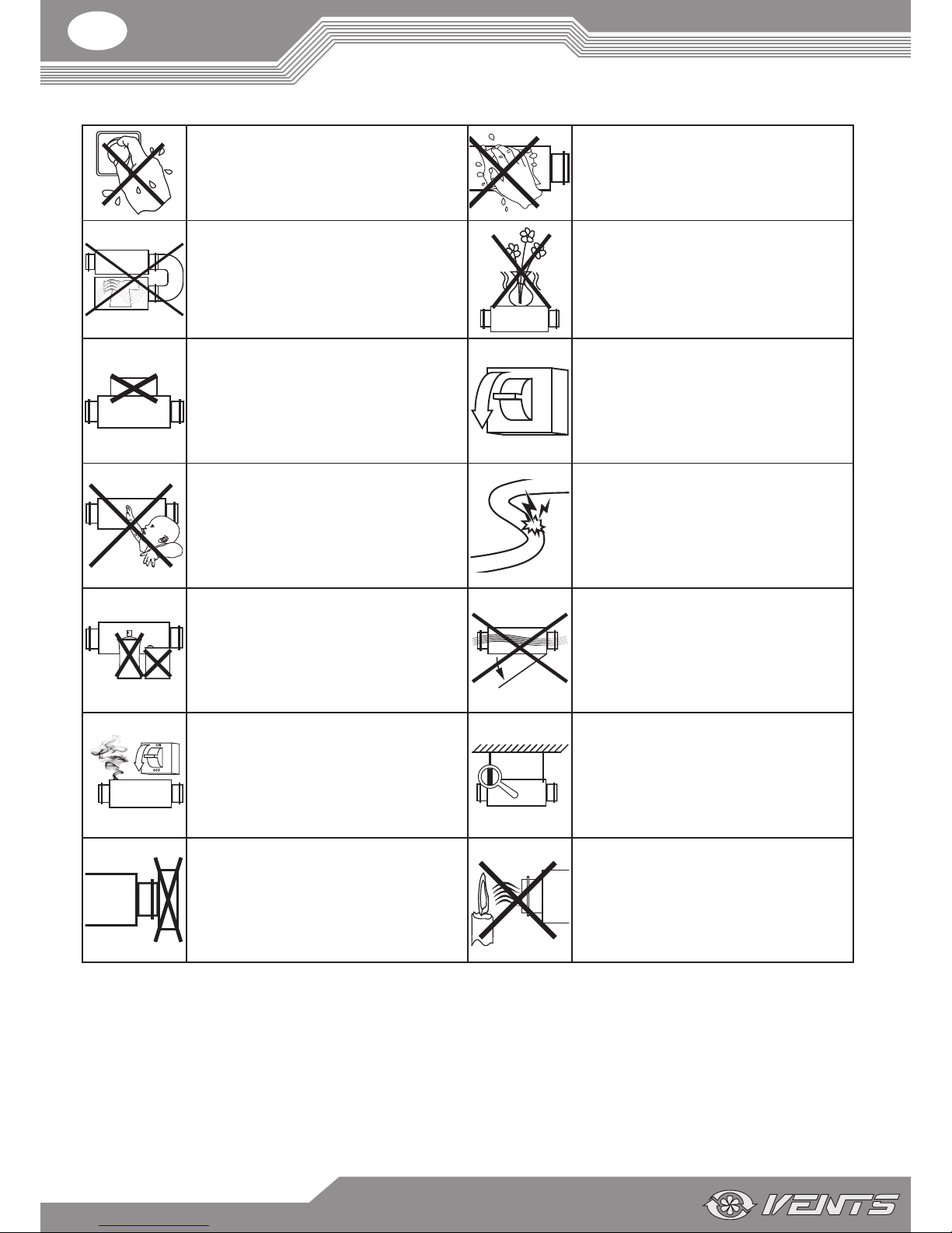
THE UNIT IS NOT INTENDED TO BE USED BY CHILDREN, PHYSICALLY OR MENTALLY DISABLED PER
SONS, PERSONS WITH SENSORY DISORDER, PERSONS WITH NO APPROPRIATE QUALIFICATION.
ALL OPERATIONS WITH THE UNIT MUST BE PERFORMED ONLY BY PROPERLY QUALIFIED PERSON
NEL AFTER THE APPROPRIATE SAFETY BRIEFING.
THE UNIT INSTALLATION SITES MUST PREVENT ACCESS BY UNATTENDED CHILDREN.
DELIVERY SET
Name Number
Unit
1 item
User's manual
1 item
Control panel
1 item
Packing box
1 item
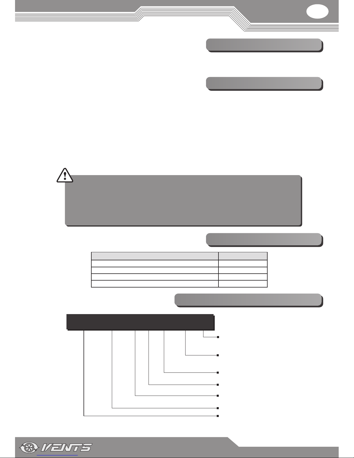
Service side
L - left
R - right
Motor type
EC - electronically commutated
Heater type
W - water heater
Unit type
VUT - ventilation with heat recovery
Mounting method
P - suspended mounting
Air capacity [m /h]
Control panel
_ - PU SENS 01 with a sensor display
A7 - PU JK 01 with an LCD display
VUT ХХХ P W ЕС - Х - X
3
DESIGNATION KEY
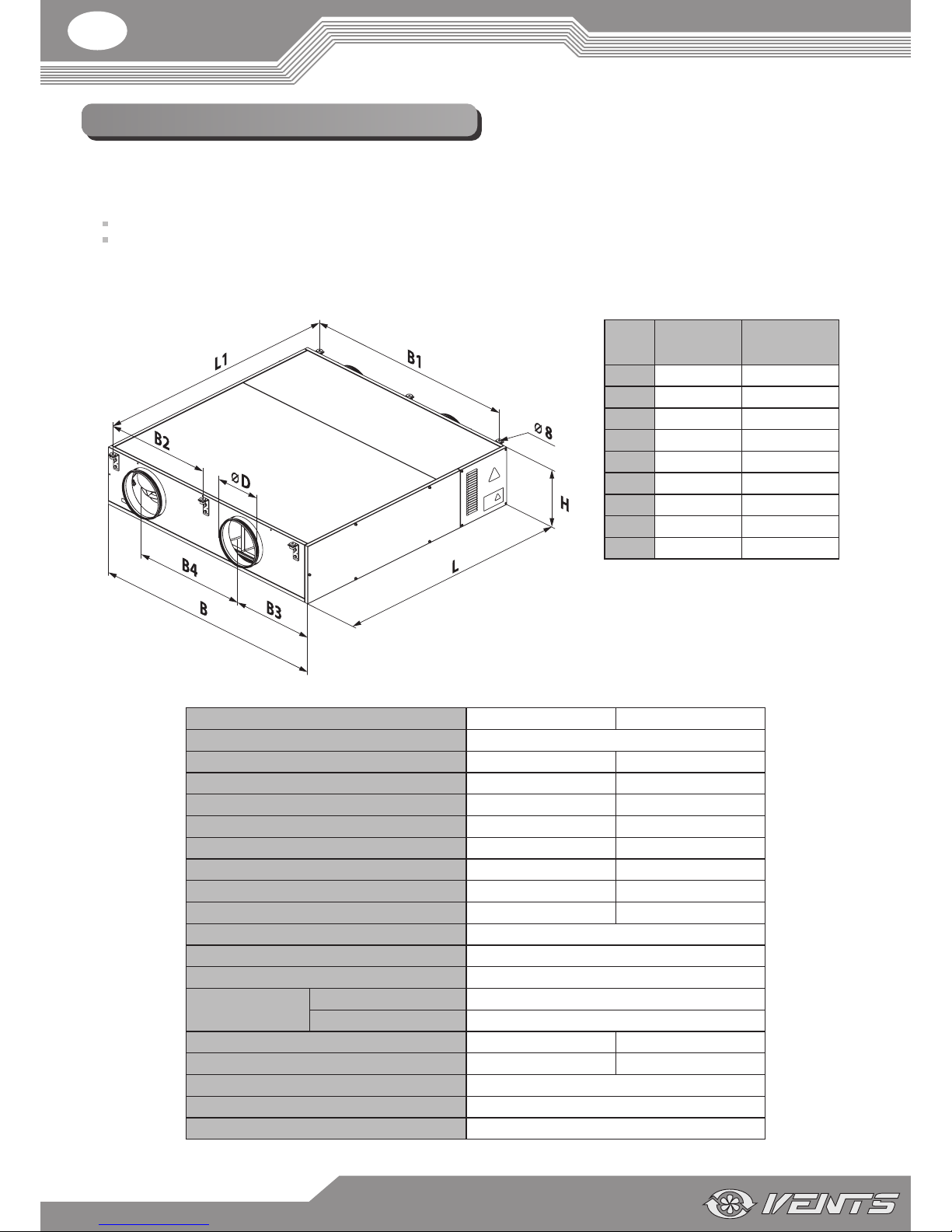
The unit with heat recovery and a water heater is designed to save heat energy by means of heat recovery and is one of the energy saving
components used in the buildings and premises. The unit is a component part and is not designed for independent operation.
The unit is designed to provide permanent controlled air exchange by means of mechanical ventilation in houses, oces, hotels, cafés,
meeting halls and other mechanically ventilated premises as well as utilization of extract air heat energy to warm up supply puried air.
The unit is designed for suspended mounting.
The unit is designed for extended periods of continuous operation without disconnection from power mains.
Transported air must not contain any ammable or explosive mixtures, evaporation of chemicals, sticky substances, brous materials,
coarse dust, soot and oil particles or environments favourable for the formation of hazardous substances (toxic substances, dust, pathogenic
germs).