www.ventilation-system.com
2
VUTR 200 V(E) EC
CONTENTS
Safety requirements....................................................................................................................................2
Purpose...............................................................................................................................................................4
Delivery set.......................................................................................................................................................4
Designation key.............................................................................................................................................4
Technical data.................................................................................................................................................5
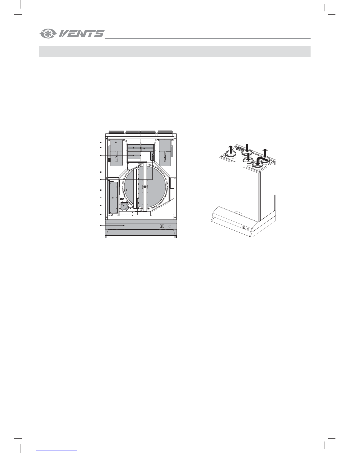
Unit design and operating principle................................................................................................6
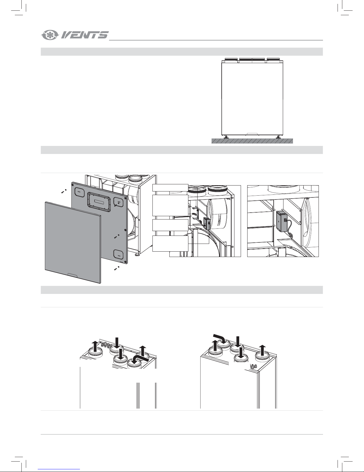
Mounting and set-up.................................................................................................................................7
Connection to power mains ..............................................................................................................12
Unit control ...................................................................................................................................................13
Technical maintenance..........................................................................................................................24
Storage and transportation regulations......................................................................................25
Manufacturer’s warranty.......................................................................................................................26
Acceptance certificate ...........................................................................................................................27
Seller information......................................................................................................................................27
Installation certificate..............................................................................................................................27
Warranty card...............................................................................................................................................27
This user’s manual consisting of the technical details, operating instructions and technical specification covers the installation and mounting of the VUTR
200 V(E) EC heat recovery air handling unit (hereinafter referred to as «the unit»).
Read the user’s manual carefully prior to installing and operating the unit.
Fulfil the user’s manual requirements as well as the provisions of all the applicable local and national construction, electrical and technical norms
and standards.
The warnings contained in the user’s manual must be considered most seriously since they contain vital personal safety information.
Failure to follow the rules and safety precautions noted in this user’s manual may result in an injury or unit damage.
After a careful reading of the manual, keep it for the entire service life of the unit.
While transferring the unit control the user’s manual must be turned over to the receiving operator.
Symbol legend:
SAFETY REQUIREMENTS
WARNING!
DO NOT!
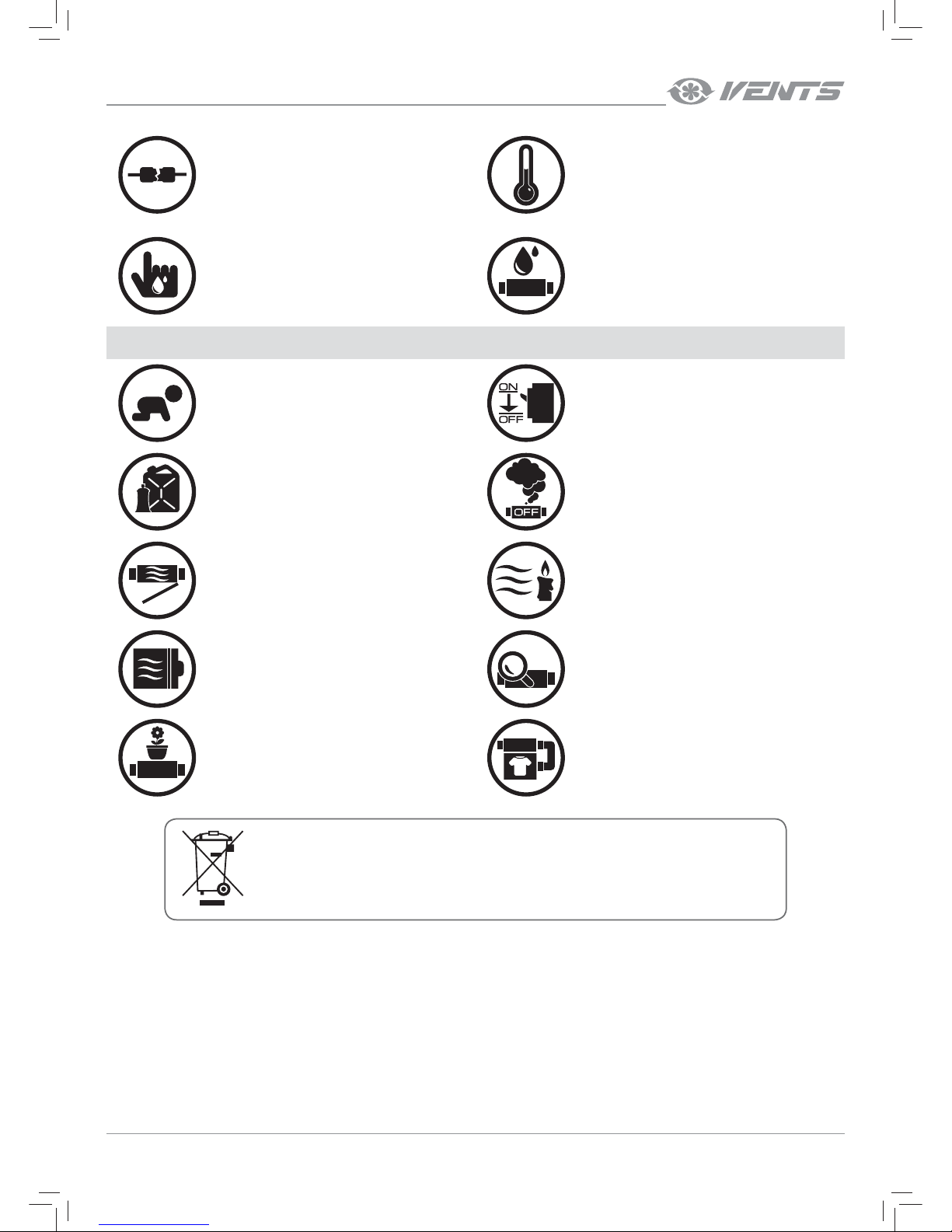
UNIT MOUNTING AND OPERATION SAFETY PRECAUTIONS
• Disconnect the unit from power mains prior to
any installation operations. •The unit must be grounded!
•Do not lay the power cable of the unit in close
proximity to heating equipment.
•While installing the unit follow the safety
regulations specific to the use of electric tools.
•Do not change the power cable length at your
own discretion.
•Do not bend the power cable.
•Avoid damaging the power cable.
•Do not put any foreign objects on the power
cable.
•Unpack the unit with care.