VRG VERACHTERT
07.02 all rights reserved
3
C O N T E N T S
page
1. PRODUCT IDENTIFICATION..................................................................................................................4
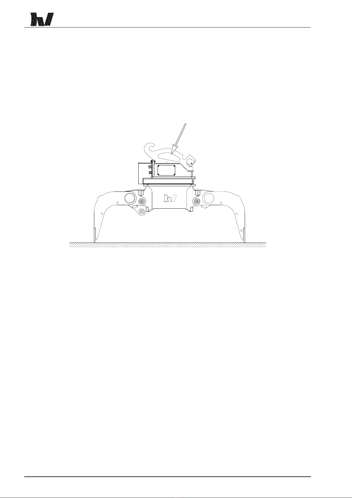
2. HOISTING THE VRG GRAB ...................................................................................................................6
3. PRODUCT OVERVIEW AND TECHNICAL SPECIFICATIONS.............................................................7
3.1 VRG-GRAB MODELS.............................................................................................................................8
3.2 OPTIONS AND CODES ...........................................................................................................................9
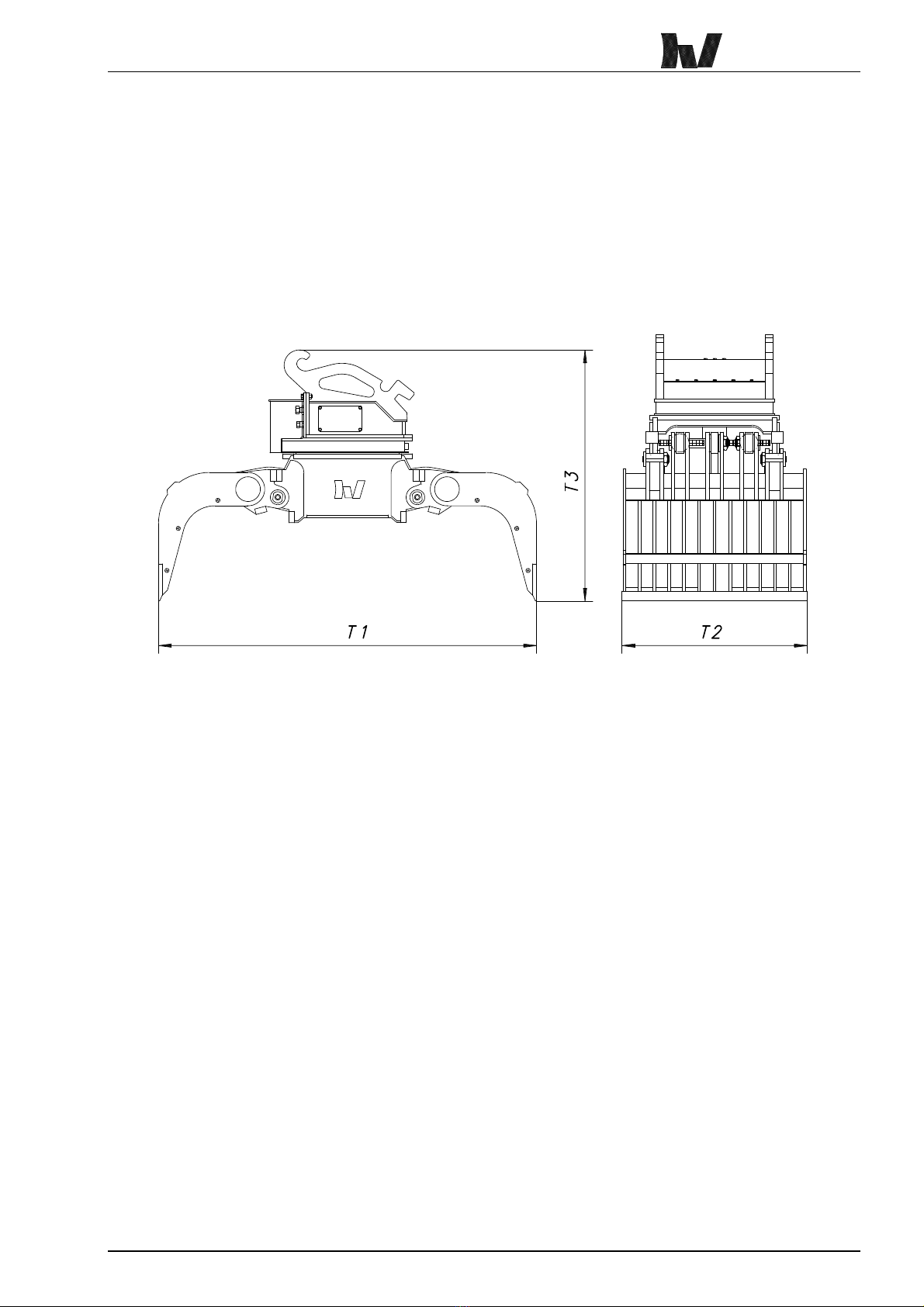
3.3 TECHNICAL DATA................................................................................................................................10
3.4 CALCULATING THE EXCAVATOR/EQUIPMENT COMBINATION ...................................................................11
4. INSTALLING THE VRG GRAB .............................................................................................................13
4.1 HYDRAULIC COUPLERS .......................................................................................................................14
4.2 MOUNTING THE VRG GRAB TO THE EXCAVATOR ..................................................................................17
4.3 VENTING THE HYDRAULIC SYSTEM.......................................................................................................18
4.4 MEASURING WORKING PRESSURES AND OPENING AND CLOSING TIMES..................................................19
5. OPERATION ..........................................................................................................................................21
6. THE APPLICATION OF LOADING AND BREAKING PLATES ..........................................................23
7. MAINTENANCE AND REPAIR .............................................................................................................25
7.1 SAFETY PRECAUTIONS .......................................................................................................................26
7.2 DAILY MAINTENANCE ..........................................................................................................................28
7.3 WELDING THE VRG GRAB ..................................................................................................................29
7.4 REPLACING REMOVABLE EDGES ..........................................................................................................29
7.5 TORQUE VALUES FOR METRIC THREAD JOINTS .....................................................................................29
8. HYDRAULIC DIAGRAM........................................................................................................................30
9. SPARE PARTS......................................................................................................................................32
WARRANTY CONDITIONS........................................................................................................................33
INFORMATION SHEET ..............................................................................................................................35